


Abstract
Ventricular rate control is considered as an initial choice of therapy in many patients with atrial fibrillation (AF). We could previously show that electrostimulation of the right inferior ganglionated plexus (RIGP), which supplies the AV node, instantly decreases ventricular rate during AF. This study describes the development of a technique to reliably implant a chronic lead inside the RIGP.
In nine mongrel dogs with AF, the RIGP was identified by neuromapping with probatory high-frequency stimulation (20 Hz) over steerable electrode catheters until a significant ventricular rate slowing was achieved. Then an active fixation, permanent pacemaker lead was fixed closed to the mapping catheter left in place as anatomical marker. Initially ( n = 4) available guiding catheters and steerable lead stylets were employed to navigate and anchor the lead, which resulted in repetitive screw-in attempts. Therefore, a guiding catheter was developed, which allowed angiography, lead advancement through its lumen, and probatory neurostimulation over its tip. This tool allowed lead delivery within 40 min ( n = 5). Neurostimulation via the permanent lead elicited negative dromotropic effects with stimulation frequency, voltage, and impulse duration as determinants of stimulation efficacy.
Active fixation of a permanent pacing lead inside the RIGP is feasible without thoracotomy. Thereby, ventricular rate control during AF can be achieved with stimulus voltages applied for myocardial electrostimulation.
Introduction
Atrial fibrillation (AF) is the most frequent cardiac arrhythmia. Recent studies have shown that in industrial countries, nearly 1% of the population is in AF; this corresponds to a number of 2.3 million people in the USA. 1 Owing to an ageing population, the incidence of AF in the USA is assumed to reach 10 million by 2050. 2
There is increasing evidence that ventricular rate control is the initial choice of therapy in many, but not all patients with AF, and a necessary component in almost all patients. This is based on numerous studies which have shown that ventricular rate control has a similar prognostic outcome as rhythm control, including patients with congestive heart failure. 3–7 Irrespective of the strategy chosen, risk stratification with respect to thromboembolic events has to occur.
According to AHA/EHRA guidelines, 8 resting heart rate should be below 80 bpm and during exercise, ventricular rate should not regularly exceed 110 bpm. Though appealing, sufficient rate control using drugs is not always easy to achieve and limited by potential side effects such as hypotension or bradycardia. 9 In addition, in AF, the instant change of short and long R–R intervals also may contribute to patients symptoms. Drugs with negative dromotropic effects may decrease the average mean ventricular rate; however, the profile of irregularity may persist.
We and others were able to show that endocardial electrical catheter stimulation of the right inferior ganglionated plexus (RIGP) elicits selective negative dromotropic effects in patients. 10 , 11 Of note, the time kinetic of these negative dromotropic effects is very short because of the rapid breakdown of acetylcholine inside the synaptic cleft by acetylcholine esterase. In fact, the rate slowing effects dissipate within 0.5–1 s after neurostimulation. This would theoretically allow an instant adjustment of the degree of parasympathetic neurostimulation in relation to rapidly changing R–R intervals. Subsequently, two animal studies demonstrated that epicardial electrical stimulation of this plexus with screw-in leads was feasible. 12 , 13 However, thoracotomy does not seem to be justified in this mostly elder patient cohort.
The present study describes a technique to reliably identify the RIGP with transvenously positioned endocardial active fixation leads within clinically acceptable time margins and may help to further develop implantable cardiac neurostimulators for ventricular rate control during AF.
Methods
Animal care, all investigations, and euthanasia were performed according to the guidelines of the American Society of Physiology and with permission of the competent authorities.
Implantation procedure
Nine male mongrel dogs (19–27 kg) were anaesthetized (propofol, 5 mg/kg body weight intravenously) and intubated, while breathing spontaneously. Analgo-sedation was maintained with fentanyl (0.5–1 µg/kg/h) and pentobarbital (0.3 mg/kg/h). An electrical heating pad under the animal was used to maintain a body temperature of 37°C. Twelve-lead surface ECG, capillary oxygen saturation, and left ventricular pressure were continuously monitored; arterial blood gas analyses were performed hourly.
Bipolar electrode catheters were positioned in the right ventricular apex and the lateral wall of the right atrium for rapid atrial pacing to induce AF and ventricular sensing. Endocardial identification of the RIGP can be achieved by high-frequency electrical stimulation as shown in patients. 10 However, the endocardial area at which negative dromotropic effects can be achieved is small. Thus, in order to position a chronic screw-in lead in this plexus using a transvenous approach, two problems had to be solved: First, the plexus had to be identified by probatory high-frequency electrical stimulation. Secondly, a stable positioning and fixation of a chronic lead in an anatomical challenging area in the infero-septal right atrium was necessary. There were two development phases until a reproducible method for implanting a permanent neurostimulation electrode was established.
Phase 1: right inferior ganglionated plexus identification and fixation of a neurostimulation lead with conventional tools ( n = 4)
In a first step, the area around the coronary sinus ostium was mapped with a deflectable six-polar stimulation catheter (Cordis-Corp., Baldwin Park, CA, USA). The catheter was introduced via an 8 F vascular sheath in the right or left femoral vein. To identify the plexus, 20 Hz stimuli (20 V, 2 ms) were delivered over the distal pair of electrodes (Grass S-88, Astro-Med, West Warwick, RI, USA). High-frequency stimulation readily induced AF. Significant ventricular rate slowing during AF indicated the correct atrial endocardial site beneath the epicardially located RIGP. During subsequent attempts to position the chronic lead, the stimulation catheter was left in place to mark the effective stimulation area.
Initially, a commercially available atrial pacing lead (Elox, Biotronik, Berlin, Germany) was used for chronic lead implantation. In order to navigate this lead to the circumscribed endocardial target area, various available tools for lead placement were tested: a steerable guidewire for pacemaker leads (Locator, Pacesetter, Solna, Sweden), and steerable as well as non-steerable coronary sinus guiding catheters commonly used for left ventricular lead implantation for cardiac resynchronization therapy (Attain Deflectable Catheter Delivery System, Medtronic, Minneapolis, MN, USA; Scout Sinus Coronarius Utility Tool, Biotronik).
Using these different positioning tools, the permanent lead was screwed in repetitively until a negative dromotropic effect was elicited during electrical stimulation (20 Hz, 20 V, rectangular pulse, pulse duration 2 ms). The negative dromotropic effect was defined as a mean R–R interval prolongation of at least 25% during 10 consecutive R–R intervals during stimulation vs. 10 R–R intervals before stimulation. At an effective site, a dose–response curve for neurostimulation was established for different stimulation voltages (2–20 V, step interval 2 V), frequencies (10–50 Hz, step-interval 10 Hz), and pulse durations (1 and 2 ms). Ventricular cycle length during AF was averaged for 10 s prior to, during, and after parasympathetic stimulation (PS). After each episode of nerve stimulation, at least 1 min elapsed.
Phase 2: development of a positioning tool for a neurostimulation lead ( n = 5)
On the basis of the experience gathered during phase 1, a specific neurostimulation lead delivery sheath was developed. The sheath incorporates small stimulation electrodes at its tip for bipolar stimulation ( Figure 1 A ). The chronic screw-in stimulation lead can be left inside the sheath just slightly behind the distal orifice during the mapping procedure. Thus, once an effective stimulation site has been identified by probatory stimulation via the sheath, the permanent electrode can be immediately fixed at this site without catheter exchange or movement of the sheath. After lead fixation, the sheath can be slit and removed.
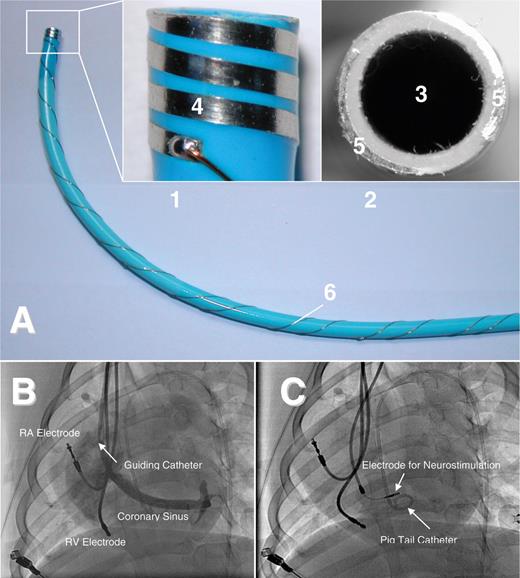
( A ) Sheath for delivery of a permanent neurostimulation lead. The small pictures are enlargements of the tip of the sheath with the incorporated electrodes (1: lateral view; 2: frontal view). The sheath has a lumen (3) which can be used for angiographic imaging of the coronary sinus and lead advancement. The incorporated electrodes allow probatory electrical stimulation to exclude ventricular capture and identify areas with negative dromotropy during high-frequency stimulation without repetitive screw-in attempts of the lead. The electrode design offers bipolar electrical stimulation with myocardial contact either in a lateral (4: electrode surface) or in a frontal (5: electrode surface) plane. 6: Wiring at the shaft of the sheath. ( B ) Left-lateral fluoroscopy of the canine heart during acute study. An additional atrial lead was implanted for induction and maintenance of AF and a ventricular lead for recording of ventricular rate. Via the guiding catheter, a coronary sinus angiography is performed to ease identification of the RIGP. Once an effective stimulation site has been identified by probatory stimulation via the bipolar electrodes at the tip of the sheath, the permanent electrode can be advanced through the sheath and immediately fixed at this site without exchange or movement of the sheath. A pigtail catheter is positioned in the left ventricle. ( C ) Screw-in electrode positioned in the RIGP for neurostimulation.
At the final implantation site, a dose–response curve for neurostimulation was recorded for both sheath and permanent electrodes. Effects of neurostimulation on ventricular rate and blood pressure were evaluated as a function of stimulation voltage as described for phase 1.
To assess short-term lead stability, the neurostimulation electrode was connected to a modified pacemaker (Logos, Biotronik), which was implanted in a subcutaneous pocket in the right side of the neck. Conventional electrodes in the right atrium and the right ventricle (Elox, Biotronik) were connected to a common DDD-pacemaker (Logos, Biotronik) which was implanted in the left side of the neck. Intermittent neurostimulation (1 V, 1 ms) was performed once a week for 3 months. During neurostimulation, all dogs were awake. Atrial fibrillation was induced during testing by rapid atrial pacing in AOO mode at 600 ppm via the implanted conventional atrial lead. The effects of neurostimulation on the ventricular rate during AF were tested as relative prolongation of the ventricular cycle length during AF with neurostimulation vs. without neurostimulation (CL PS /CL).
Statistical analysis
Results are presented as mean ± 1 standard deviation. Neurostimulation effects were analysed by ANOVA for repeated measurements. Two-sided Student's t -test was used to compare procedural data. P -values of < 0.05 were considered significant.
Results
Phase 1: right inferior ganglionated plexus identification and fixation of a neurostimulation lead with conventional tools
The permanent lead has to be navigated precisely to the small target region of the RIGP. To facilitate identification of the RIGP area, functional neuromapping by probatory high-frequency stimulation was first performed with a conventional six-polar deflectable catheter. The catheter was left as a marker at the successful stimulation site. For subsequent lead implantation, conventional stylets bent manually to achieve a distal curvature or deflectable lead stylets (Locator, Pacesetter AB) were employed initially. However, rotational stability of the electrode was poor. In addition, once an effective site had been identified, lead fixation was difficult to achieve. This was due to the fact that there was an angle of ∼90° between the shaft of the lead inside the SVC and the distal part which was orientated orthogonal to the inferior right atrial septum or the posterior wall of the coronary sinus ostium. Thus, the axial force during screw-in attempts did not easily translate to the tip of the lead, frequently resulting in dislodgement during fixation attempts.
Thereafter, steerable and non-steerable coronary sinus guiding catheters were employed which are used for left ventricular lead placement for cardiac resynchronization (Attain Deflectable Catheter Delivery System, Medtronic; Scout 8F Sinus Coronarius Utility Tool, Biotronik). Initially, the guiding catheter with the distally protruding permanent lead was used to contact the target area and probatory stimulation via the lead was delivered after fixation. This resulted in multiple screw-in attempts in the posteroseptal right atrium and proximal coronary sinus. Thus, to avoid repetitive active fixation attempts, a deflectable six-polar stimulation catheter was advanced through the sheath. Mapping and stimulation were performed with this catheter. Once a site with a sufficient negative dromotropic effect had been identified, the catheter was withdrawn and the permanent lead was introduced while leaving the guiding catheter in place. Unfortunately, this manoeuvre often resulted in dislodgement of the guiding catheter during exchange of the catheter and lead.
Generally, fixation of the lead was hampered by the anatomical peculiarity of the endocardial surface at the effective stimulation site. The RIGP epicardially superimposes the orifice of the coronary sinus at its junction to the right atrium and inferior vena cava. During lead fixation attempts, the lead frequently slipped into the inferior vena cava. This way the ‘mapping’ of the RIGP and electrode implantation required long fluoroscopy and implantation times (68 ± 22 and 153 ± 43 min, respectively) with a total procedure time of 275 ± 38 min. On the basis of these observations, we decided to develop a delivery sheath particularly suited for neuromapping and active fixation of permanent neurostimulation electrodes (see phase 2).
Phase 2: development of a positioning tool for a neurostimulation lead
The positioning tool ( Figure 1 ) integrated several functions sequentially needed during the implantation process: angiography, electrical stimulation, and electrode delivery. After central venous access, the sheath was advanced into the inferior vena cava and the obturator and wire were withdrawn. After flushing with saline solution, the tip electrodes were connected to the stimulator. The sheath was then withdrawn from the inferior caval vein and directed to the ostium of the coronary sinus in a 40° LAO view. Small boli of contrast agent were given to identify the coronary sinus orifice ( Figure 1 B ). Then, the permanent lead was inserted into the lumen of the sheath and the tip of the lead was advanced ∼1 cm behind the tip of the sheath. A custom-made bipolar lead with a fixed screw of 2.7 mm (Biotronik) was used in conjunction with the delivery sheath. The sheath was then rotated to face the posterior limbus of the coronary sinus and the inferior posteroseptal space. Probatory stimulation was then performed (150 ppm, 20 V, 0.5 ms) to exclude ventricular myocardial capture during subsequent high-frequency stimulation. If no ventricular capture occurred, high-frequency stimulation at 20 Hz with increasing voltages from 2 to 20 V was initiated. If a ventricular rate slowing of more than 25% occurred at voltages up to 20 V, the sheath was left in place and the permanent lead was advanced and screwed into this area ( Figure 1 C ). Thereafter, probatory low-frequency stimulation (150 bpm, 7.5 V, 1 ms) was delivered over the lead to exclude ventricular capture. Subsequent high-frequency stimulation via the lead confirmed the negative dromotropic effect.
The multifunctional design of the sheath sped up the mapping and implantation process. The ease of fixation was further improved by the use of a bipolar lead with a longer screw at the distal tip which made it easier to anchor the permanent lead inside the plexus. Overall, the customized delivery catheter significantly decreased fluoroscopy time to 26 ± 9 min, lead implantation time to 37 ± 12 min, and total procedure time to 154 ± 27 min ( P < 0.01 vs. phase 1, respectively).
Electrical determinants of cardiac neurostimulation
Neurostimulation resulted in a decrease of ventricular heart rate during AF ( Figure 2 ). Of note, the on-/offset of the negative dromotropic effect was sudden within 500 ms after the initiation or termination of PS. Muscarinergic blockade with atropine completely abolished the negative dromotropic effect during PS. For a constant impulse duration of 0.5 ms, the negative dromotropic effect increased with increasing stimulus voltage ( Figure 3 A ).
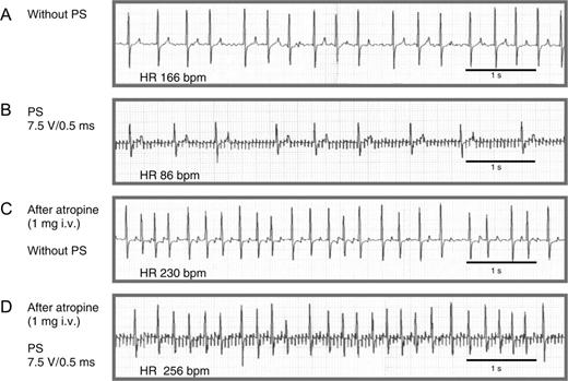
ECG tracings illustrating the negative dromotropic effect of neurostimulation during AF and its dependence on muscarinergic receptor activation. ( A ) Atrial fibrillation with rapid ventricular rate but without PS. ( B ) Neurostimulation with a stimulation voltage of 7.5 V, impulse duration of 0.5 ms, and stimulation frequency of 20 Hz results in a significant reduction of the average ventricular rate from 166 to 86 bpm. ( C ) Administration of 1 mg atropine iv increases heart rate to 230 bpm without neurostimulation. ( D ) After injection of atropine, the neurostimulation effect is no longer reproducible. Paper speed 25 mm/s.
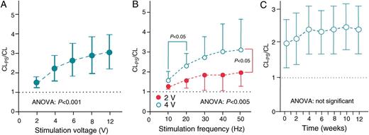
( A ) Dose–response curve for neurostimulation. The negative dromotropic effect during AF and PS at 20 Hz and an impulse duration of 0.5 ms is presented as a ratio of the CL during PS to CL prior to PS (CL PS /CL). CL PS /CL significantly increased with increasing stimulation voltage ( P < 0.001, ANOVA). ( B ) Influence of stimulation frequency on the negative dromotropic effect: CL PS /CL significantly increases with higher stimulation frequencies at constant stimulation voltage and an impulse duration of 0.5 ms. The most distinct prolongation in ventricular cycle length occurs between 10 and 20 Hz, whereas an additional cycle length prolongation between 20 and 50 Hz is moderate. At higher stimulus strength of 4 V, a significant increase of the negative dromotropic effect was observed ( P < 0.05 all besides 10 Hz). ( C ) Weekly intermittent neurostimulation reveals a sustained negative dromotropic effect over 3 months: during PS (stimulation voltage 1 V; impulse duration 1 ms), ventricular cycle length during AF remains longer than without PS (CL PS /CL) by a factor of ∼2. During the first 4–6 weeks, there was a non-significant trend towards a further increase in the rate slowing effect until the effect reached a plateau.
The negative dromotropic effect significantly increased at higher stimulation frequencies ( Figure 3 B ). During 10 Hz stimulation with a voltage of 2 and 4 V, the ventricular cycle length increased by a factor of 1.27 ± 0.13 and 1.57 ± 0.45, respectively. At 50 Hz, the effect on heart rate slowing was more evident, resulting in an increase in the ventricular cycle length by factors of 1.96 ± 0.45 and 3.1 ± 1.54, respectively (ANOVA P < 0.005). The most significant prolongation in ventricular cycle length occurred between 10 and 20 Hz. At higher frequencies, the cycle length prolongation reached a plateau.
Weekly intermittent neurostimulation revealed a sustained negative dromotropic effect over 3 months ( Figure 3 C ). Of note, there was a non-significant trend towards an increase in the rate slowing effect during the first 4–6 weeks until the effect reached a plateau.
To investigate whether the efficacy of different stimulation parameters during PS using the guiding catheter may mirror the efficacy of PS subsequently using the screw-in electrode, the negative domotropic effect was plotted over different stimulation frequencies ( Table 1 ). During stimulation with a constant voltage of 2 V, the negative dromotropic effect was three-fold higher during stimulation over the active fixation electrode than for stimulation via the guiding catheter. Importantly, the relative efficacy over different frequencies was comparable. Thus, stimulation over the guiding catheter could predict the efficacy achieved during subsequent stimulation over the permanent lead.
Neurostimulation effects on cycle length prolongation using the combined electrostimulation/guiding catheter or the permanent screw-in lead
| Stimulation frequency (Hz) | 10 | 20 | 30 | 40 | 50 |
| Guiding catheter | 1.3 ± 0.3 | 1.6 ± 0.4 | 1.8 ± 0.8 | 1.9 ± 0.8 | 2.0 ± 0.8 |
| Screw-in electrode | 4.3 ± 0.6 | 5.2 ± 0.5 | 6.1 ± 0.7 | 6.1 ± 0.7 | 6.5 ± 1.2 |
| Stimulation frequency (Hz) | 10 | 20 | 30 | 40 | 50 |
| Guiding catheter | 1.3 ± 0.3 | 1.6 ± 0.4 | 1.8 ± 0.8 | 1.9 ± 0.8 | 2.0 ± 0.8 |
| Screw-in electrode | 4.3 ± 0.6 | 5.2 ± 0.5 | 6.1 ± 0.7 | 6.1 ± 0.7 | 6.5 ± 1.2 |
The PS effects on CL prolongation are depicted as CL during PS/CL before PS (CL PS /CL). For each frequency, the CL PS /CL prolongation during stimulation via the custom-made delivery sheath is compared with stimulation via the permanent lead, which was screwed in at the same location after advancement through the sheath. A three-fold increase in the negative dromotropic effect was obtained using the delivery sheath compared with the implanted electrode ( P < 0.01 for all frequencies, impulse duration: 2 ms). The degree of rate slowing increased with increasing stimulation frequency using both devices.
Discussion
The present study provides a technique which allows implantation of an active fixation lead into parasympathetic neural structures that supply the AV node to decrease the ventricular rate during AF. The technique obviates the need for thoracotomy as required in previous studies 12 , 13 while the time needed for neuromapping and implantation is within clinically accepted margins, e.g. those known for cardiac resynchronization therapy.
Implantation of a neurostimulation lead differs from other lead implantation procedures employed so far in the heart. This is due to the fact that the neural structures have to be identified by applying new electrical stimulation patterns and algorithms. This includes probatory high-energy stimulation to exclude ventricular capture and high-frequency stimulation to identify the nerves. Another difference lies in the fact that the target area of the neural fibres is rather small and located at an anatomically challenging right atrial site close to the ostium of great vessels (e.g. coronary sinus, inferior vena cava) which bares the risk of lead dislocation into these vessels during the fixation process. The combined electrostimulation-guiding catheter approach allowed the reliable positioning of the permanent lead.
Although the neurostimulation approach described herein carries the potential to improve ventricular rate control during AF, chronic stimulation efficacy and safety will have to be shown both in animals and in patients. This safety provided one may envision that neurostimulation may be advantageous in patients in whom pharmacological rate control cannot be adequately achieved or in whom drug intolerance due to side effects occurs. Thus, the technique described here is not likely to replace standard rate control drugs, but may help to achieve rate control when such drugs are not successful for rate control. Even in studies which try to optimize ventricular rate control during AF like the AFFIRM trial, the percentage of patients with insufficient rate control, despite the use of up to three negative dromotropic drugs, reaches 20%. 3 In these patients, His bundle ablation and subsequent implantation of a ventricular pacemaker may help to definitely control ventricular rate. This, however, may promote deterioration of left ventricular function, especially in patients with pre-existing congestive heart failure. Accordingly, acute stimulation of parasympathetic nerve fibres to the AV node in animal models of AF has been demonstrated to be haemodynamically superior to His bundle ablation and subsequent right ventricular pacing. 14 This may be due to the fact that cardiac parasympathetic neurostimulation preserves the normal atrioventricular nodal conduction with narrow QRS complexes.
High ventricular rates during AF also occur during catecholamine treatment of acute heart failure. In fact, up to 40% of patients with acute heart failure develop AF. 15 Since PS does not decrease systemic vascular resistance or ventricular inotropy like other negative dromotropic therapies (e.g. beta-blockers, calcium channel antagonists), it may offer an alternative approach to ventricular rate control in these patients. 10 , 16 , 17 Since temporary screw-in electrodes are available on the market, the technique introduced herein may allow to position such a temporary screw-in electrode inside the postero-inferior right atrium to achieve negative dromotropic effects.
There are other clinical applications which also might benefit from such an approach: permanent His bundle pacing, for example, requires placement of an active fixation lead close to the tiny His bundle. 18
Recording of a His potential with the guiding catheter prior to implantation of the permanent lead may indeed avoid multiple screw-in attempts with the active fixation lead. Likewise, recording of the intracardiac electrogram from the tip of the guiding catheter may ease the identification of the coronary sinus without contrast medium during implantation of left ventricular leads for cardiac resynchronization therapy. This may ease identification of the CS, especially in patients with renal failure in whom lowest amounts of contrast medium are desired.
Limitations
The study does not provide a long-term follow-up of chronic continuous neurostimulation. Rather it provides a technique for stable short-term positioning of a neurostimulation lead inside the atrium. Although we did not observe lead dislocation after final fixation of the screw-in electrode in this experiment with a short follow-up of 3 months, dislodgement of the neurostimulation electrode theoretically carries the risk of inducing ventricular fibrillation. Delivery of high-frequency stimuli during the ventricular refractory period (e.g. 200 Hz stimuli as stimulus package during a 50 ms period coupled to the R-wave) may decrease this risk, but this remains to be shown.
Similarly, in patients with paroxysmal AF, continuous high-frequency stimulation will readily induce AF. In these instances, high-frequency stimuli may be coupled to the local atrial electrical deflection, thus being delivered during the atrial refractoriness. Of note, such an algorithm proved to be practical during acute catheter stimulation of parasympathetic nerves in humans. 10
The dog does not show a Eustachian ridge (vestigial valve of the inferior vena cava), which is prominent in man. Thus, although the developed approach may be optimal in the dog, a modified tool kit for implantation in patients may have to be developed. This may include different curvatures or even a deflectable combined stimulation and guiding catheter. Since identification of the plexus with stimulation catheters introduced via the femoral vein can be easily achieved in man, 10 a femoral approach might be evaluated in the case of failure to implant permanent leads via the superior caval vein in man. However, this might limit the clinical applicability since implantation of a long lead via the femoral vein including an abdominal device might not be justified by the clinical benefit.
Because of the multiple (screw-in) attempts to deliver the lead in phase 1, we did not perform histological analysis in this phase. After 3 months of chronic intermittent stimulation, limited histological analysis of the implantation site was done in two dogs. In these dogs, the screw-in site was actually close to neurofilament-positive but tyrosine hydroxylase-negative neural fibres, but the area was devoid of ganglionic cells. This supports the idea that actually axons on passage to the AV node were stimulated. However, the number of investigated animals was too low to draw any final conclusion on this question. In addition, systematic sectioning of the implantation site and AV nodal area would be required to find out the relationship of the lead with respect to the RIGP.
Funding
This study was supported by the German Atrial Fibrillation competence NETwork (AFNET) (grant number 01 GI 0204) and by Biotronik GmbH & Co. KG, Berlin, Germany (grant number 372049).
Acknowledgements
We thank Mr Oliver Schweika, PhD, from Biotronik GmbH, Berlin, Germany, for his excellent contribution to all aspects of the study, especially pacemaker design and programming, technical, administrative, and logistic support.
Conflict of interest: none declared.
References
Author notes
These authors contributed equally to the study.
