


Abstract
K-ion batteries (KIBs) are a widely attractive alternative to Li-ion batteries. While avoiding scarce/toxic elements in their construction, the low standard electrode potential of K+/K allows a low cut-off potential of the negative electrode and high operation voltages that are competitive with those observed in LIBs. Because of the wide operating potential range, developing improved non-aqueous electrolytes with higher oxidation stability and the ability to passivate low-potential negative electrodes is one of the major challenges of high-voltage KIB production. This account primarily covers our recent studies on non-aqueous electrolytes design based on potassium salt and solvent properties. We also discuss remaining/emerging challenges and provide our perspective on non-aqueous electrolytes for high-voltage KIBs.
1. Introduction
The importance of electric energy storage technologies continues to increase for achieving sustainability in our society. With growing concerns about global warming, there is a strong need to minimize greenhouse gas emissions as well as consumption of fossil fuels. Efficient use of renewable energy generated from sustainable natural resources such as sunlight, wind, tides, and waves is desired, but tapping into these resource supplies incorporates a different problem of unstable energy supply due to weather fluctuations. Therefore, energy storage systems capable of meeting this large-scale supply and demand are necessary to balance electricity supply and improve energy efficiency.
Rechargeable batteries are one of the most promising means for storing this energy because of their high energy efficiency compared with other energy storage technologies. Among practical rechargeable batteries, LIBs are widely utilized as a power source for a variety of electronic devices due to their high energy density.1,2 Also, they have provided power for electric vehicles (EVs), plug-in hybrid vehicles (PHVs), and hybrid vehicles (HVs) since around 2009. Recently, LIBs have also been utilized for stationary applications in energy storage systems. However, Li and Co, which are utilized in LIBs, are elements that are not abundant in the Earth’s crust.3,4 Therefore, the rapid growth of the LIB market and the increasing demand for these material resources have raised concerns about the long-term availability of these resources.5 In addition, Li and Co resources are unevenly distributed across the globe. These economic and geographical limitations have pushed forward efforts to develop novel rechargeable batteries to replace LIBs.
As an alternative to LIBs, rechargeable Mg batteries6 and Na-ion batteries (NIBs),7 utilizing Mg2+ and Na+ as carrier ions, have been studied due to their high Earth abundance. In addition, Mg batteries should provide high energy densities due to large charge-to-mass ratio of metallic Mg electrode. While NIBs can exhibit high power density due to the faster migration of Na+ compared with Li+.7,8 Since 2015, K-ion batteries (KIBs) have attracted considerable attention. Not only K resources are inexhaustible, but KIBs are also expected to operate at higher voltages than NIBs and LIBs. We have proved that the standard redox potential of K+/K electrodes in some non-aqueous electrolytes, including carbonate ester electrolytes, can be even lower than that of Li+/Li.9–11 This low standard electrode potential of the K+/K electrode allows a low cut-off potential of the negative electrode, which does not require the deposition of potassium metal. Thus, KIBs can operate over a wider voltage range than NIBs or LIBs when we assume the same cut-off potential of positive electrode. Moreover, KIBs would achieve high power density because of the faster diffusion of K+ ions, which have weaker Coulombic interactions than Li+, Na+, and Mg2+. Because of these unique characteristics, KIBs are believed to be an ideal replacement for LIBs. Since the demonstrations of low K+/K potentials and reversible electrochemical insertion of K with graphite in 2015,11–13 positive/negative electrode materials for KIBs have been extensively studied.10,14–21
Previous studies have also revealed the importance of the electrolyte in achieving high performance for various electrode materials.22–24 So far, non-aqueous electrolytes have been the main focus for developing KIBs. As such, their development and improvement are essential to the large-scale use of high-voltage KIB full cells. A non-aqueous electrolyte must possess high ionic conductivity, high oxidation stability, as well as the ability to passivate the Al current collector at high potentials; it should also form an appropriate solid electrolyte interphase (SEI) on the negative electrode.25 In this account, we describe our recent studies on non-aqueous electrolytes for KIBs and provide perspectives on electrolytes for high-voltage KIBs.
2. Overview of K-ion Electrolytes
Figure 1 provides an overview of the electrolyte salts and solvents applied for KIBs in the 223 studies on positive electrodes, negative electrodes, and full cells published up to 2020. The most common salt was KPF6, while the second was potassium bis(fluorosulfonyl)amide (KN(SO2F)2, KFSA). KPF6-based electrolytes were utilized in approximately 80% of these studies because they have multiple advantages, including electrochemical stability and the ability to passivate Al foil. Because typical KFSA-based electrolytes undesirably promote Al foil corrosion at high potentials, these electrolytes are mainly used for the study of negative and positive electrode materials operating at potentials below 4 V vs. K+/K. Furthermore, some studies have shown that electrolytes with KFSA improved the Coulombic efficiency and cyclability of the negative electrode because the SEI on the electrode is more stable than that of KPF6.26,27 Therefore, KFSA is often chosen to test full cells where the Coulombic efficiency directly affects the cyclability.28,29 This is evidenced by the large proportion of publications (33%) using KFSA electrolytes in full cells (Figure 1a). On the other hand, KClO4 and KBF4 are rarely used for electrolytes because of solubility issues in non-aqueous solvents. Figure 1b and 1c summarize the solvents used for KPF6 and KFSA electrolytes, respectively. Carbonate ester solvents such as EC:DEC mixtures are the most commonly used solvents because of their high electrochemical stability and high solubility of K salts. Ether solvents, especially glymes such as monoglyme, are also used because of their low viscosity and high cathodic stability. Some ionic liquid (IL) electrolytes containing K+ ions have also been reported to possess flame-retardant properties. In the next section, the characteristics of electrolyte salts and solvents and their selection are discussed in detail.

Electrolyte salts and solvents of the electrolytes used in 223 studies on full K-ion battery (KIB), negative electrode (NE) and positive electrodes (PE) for KIBs: (a) frequency of electrolyte salts of KPF6. KN(SO2F)2 (KFSA), KN(SO2CF3)2 (KTFSA), KBF4, and KClO4, (b) frequency of solvent types for KPF6-based and (c) KFSA-based electrolytes grouped by ethylene carbonate (EC):diethyl carbonate (DEC), EC:dimethyl carbonate (DMC), EC:propylene carbonate (PC), other carbonate esters, monoglyme (G1), other ethers/glymes, and ionic liquids.
3. Electrolyte Design Strategy
Since K+ ions have weaker Lewis acidity than lighter alkali metal ions of Li+ and Na+ ions, they display weaker interactions with Lewis bases such as anions and solvents. Here, we describe the physical and transport properties of K salts, including solubility, ionic conductivity, viscosity, and oxidation/reduction stability of solvents and anions. The solubility of potassium electrolyte salts in non-aqueous solvents tends to be lower than that of equivalent Li and Na salts. The dissolution of these salts can be described by the Born-Haber cycle, and the Gibbs free energy of dissolution (ΔG):
where ΔG0lattice and ΔG0solvation are the lattice and solvation Gibbs energies of the salt, respectively. K+ ions show lower solvation energy than Li+ and Na+ ions for aqueous and non-aqueous systems, resulting in their lower solubility.30 On the other hand, K salts with a low lattice energy can be highly soluble. The lattice energy is highly correlated with ionic radii31 and lattice volume;32 large counter anions typically lower the lattice energy. Thus, the presence of a large counter anion is advantageous for high solubility. Figure 2 shows the solubility of Li, Na, and K salts in propylene carbonate (PC) solvent as a function of counter anion size. LiCl shows low solubility, whereas LiBr, LiBF4, and LiClO4 show high solubilities of >1 M. Although NaCl and NaBr show low solubilities (<10−2 mol L−1) compared with Li salts, NaClO4 and NaPF6 show solubilities of ∼1 M or more. A counter anion smaller than PF6− decreases the solubility of K salts to the order of 10−3–10−2 M, whereas KPF6 has a solubility of ∼0.8 M, making it more applicable to electrolyte salts. Overall, in sufficiently soluble salts, the size of the counter anion tends to increase in proportion with the size of the cation, and K salts that have anion sizes larger than PF6− are a promising alternative for K electrolytes in terms of solubility. Typical electrolyte salts with large anion sizes are amide salts, such as KFSA. Indeed, we have experimentally confirmed that the solubility of KFSA in a PC solvent is >3 M due to weaker ionic association between the K+ and FSA− anions.24 Moreover, the KFSA solution showed higher conductivity than a KPF6 solution of the same concentration in multiple solvents such as EC:DEC, PC, and monoglyme.24,26
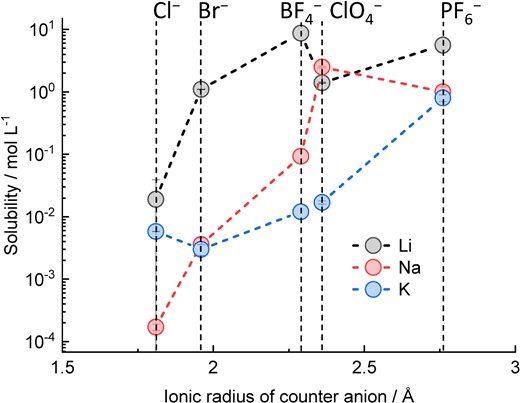
Solubility of several Li, Na, and K salts in PC as a function of the ionic radius of the counter anion. Data were derived from Ref. 33.
In addition to ionic conductivity, our previous studies demonstrated that K salts affect the charge–discharge performance, especially the Coulombic efficiency of graphite electrodes. Figure 3a and 3b show the charge–discharge curves and Coulombic efficiencies of K||graphite cells filled with 0.75 mol kg−1 KPF6/EC:DEC electrolyte and 1 mol kg−1 KFSA/EC:DEC.26 Both cells showed an initial discharge capacity of >250 mAh g−1, whereas the KFSA electrolyte cell had a lower initial irreversible capacity and higher Coulombic efficiency than the KPF6 electrolyte cell. Furthermore, the KFSA electrolyte cell showed a higher Coulombic efficiency than the KPF6 electrolyte cell in subsequent cycles (Figure 3b). This trend is different from that observed for Li||graphite cells, wherein both LiPF6 and LiFSA showed high Coulombic efficiencies (Figure 3b). These results highlight that the type of electrolyte salt has a significant impact on the graphite electrode performance in KIBs. Figure 3c summarizes the design strategy of binary KPF6 and KFSA electrolytes based on the inherent KPF6 and KFSA salt properties. Although KFSA has excellent solubility, ionic conductivity, and SEI formation ability, typical KFSA-based electrolytes corrode an Al current collector at high potentials, thus limiting their application in high-voltage KIBs. The Al corrosion issue can be overcome by using highly concentrated KFSA electrolytes (Figure 3c)24,34 and KFSA-containing ILs.35,36 In contrast to KFSA, most KPF6 electrolytes exhibit low Coulombic efficiencies with graphite electrodes because of insufficient SEI passivation. This dilemma can be resolved by using a KPF6-KFSA binary salt electrolyte with an appropriate salt ratio; this electrolyte will realize both Al passivation and high Coulombic efficiency (Figure 3c). Our studies on highly concentrated KFSA electrolytes, KFSA IL electrolytes, and KPF6-KFSA binary salt electrolytes will be presented in detail in later sections.
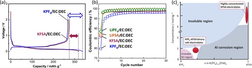
(a) Charge–discharge curves for graphite electrodes in K cells filled with KPF6/EC:DEC and KFSA/EC:DEC electrolytes. (b) Coulombic efficiencies of Li||graphite and K||graphite cells filled with APF6 and AFSA (A = Li and K) electrolytes. (c) Plot of KPF6-KFSA molar ratio vs. concentration for K-ion electrolytes. (b) Reproduced from Ref. 26 with permission. Copyright, 2020 American Chemical Society.
4. High Concentration Electrolytes
4.1 KFSA/Monoglyme System
First, various highly concentrated KFSA solutions were prepared using common electrolyte solvents such as monoglyme, PC, and γ-butyrolactone (GBL), and their ionic conductivities and viscosity were evaluated.24 We found that the KFSA/monoglyme solution showed higher ionic conductivity and lower viscosity than the others, as well as a high solubility of up to 7 mol kg−1. The potential window of the highly concentrated KFSA/monoglyme solution was evaluated through cyclic voltammetry (CV) as shown in Figure 4a. Highly concentrated solution realized highly reversible K plating/stripping nearly 0 V (vs. K+/K). Moreover, the highly concentrated electrolyte cell showed negligible oxidation peak at high potential, which was observed in the 2 mol kg−1 solution. The microscopic image of Al working electrode after CV measurement confirms that significant pitting corrosion of Al foil in the 2 mol kg−1 KFSA/monoglyme cell (Figure 4b).37 In contrast, an Al electrode cycled in 7 mol kg−1 KFSA/monoglyme showed a smooth surface (Figure 4c), indicating Al corrosion was unlikely with this electrolyte. These results indicate that the highly concentrated KFSA/monoglyme possessed a wide potential window and demonstrated Al passivation.
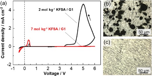
(a) Cyclic voltammograms of Al working electrodes in 2 mol kg−1 and 7 mol kg−1 of KFSA/monoglyme (G1) electrolytes using a scan rate of 0.5 mV s−1 in voltage ranges of 2–−0.5 V and 2–6 V in K||Al cells. Microscopic images of Al working electrodes tested in (b) 2 mol kg−1 KFSA/G1 and (c) 7 mol kg−1 KFSA/G1 after three cycles of CV measurement in voltage ranging from 2–6 V. Reproduced from Ref. 24 with permission. Copyright, 2018 The Royal Society of Chemistry.
The highly concentrated electrolyte also exhibited stable performance with the positive and negative electrodes of high-voltage KIBs. Figure 5a shows the charge–discharge curves of K2Mn[Fe(CN)6] (KMnHCF) and graphite electrodes in K half-cells containing a highly concentrated KFSA/monoglyme electrolyte. The KMnHCF electrode displayed improved Coulombic efficiency and capacity retention across 150 cycles in the KFSA/monoglyme electrolyte compared with 1 mol dm−3 KPF6/EC:PC (Figure 5a, b). The K||graphite cell delivered an initial reversible capacity of ∼260 mAh g−1, with stepwise voltage plateaus attributed to the staging structure. The initial Coulombic efficiency was over 80% in the highly concentrated electrolyte, which was significantly higher than the Coulombic efficiency (∼65%) obtained with 0.8 mol dm−3 KPF6/EC:DEC (Figure 5c). In the subsequent cycles, the graphite electrode in 7 mol kg−1 KFSA monoglyme showed much higher Coulombic efficiency and capacity retention than that using 0.8 mol dm−3 KPF6/EC:DEC (Figure 5c). Despite the viscous nature of the electrolyte at higher concentrations, the graphite electrodes with 7 mol kg−1 KFSA/monoglyme showed an improved rate performance over those with 0.8 mol dm−3 KPF6/EC:DEC.24 The excellent rate performance of graphite electrodes can be attributed to the fast desolvation kinetics or low SEI resistance.38
![(a) Charge–discharge curves of the K2Mn[Fe(CN)6] (upper) and graphite (bottom) electrodes in K cells filled with 7 mol kg−1 KFSA/monoglyme (G1) solution, and cycling performance and Coulombic efficiency of the (b) K2Mn[Fe(CN)6] and (c) graphite electrodes. Reproduced from Ref. 24 with permission. Copyright, 2018 The Royal Society of Chemistry.](https://oup.silverchair-cdn.com/oup/backfile/Content_public/Journal/bcsj/95/4/10.1246_bcsj.20210412/3/m_20210412fig05rgb.jpeg?Expires=1748390317&Signature=i4X83kF0R5dO-9oASIe8AfWi64UQIt5RAFCaz0Bg44bDtFpAeYxYfKy2BkzdUv~Au7FXnzrjlgG8TNI8NJj79BU2fzYxedqSdXuL3lGHDLJzA96-QjRlMBp75y3xwa275~qOEOuaegeLlLumotEg6v1iBFhMNqpME9~Sxqt89zm9vyqfrI--JY2CxkNvNYrc3WtPnFty2h9cweT36lM8nrFXZP5XgPIR~wFHdVyKuoDVXTqpVq4g-ymafNEgLOH5VZ9wC9P~LzQRhpGXHoQN1D92ykFbIafjcVCDIKzqwD1OR8ZCV94LNpVYKpGJr2DC-20AU0UMtzNXHIWto~qPHA__&Key-Pair-Id=APKAIE5G5CRDK6RD3PGA)
(a) Charge–discharge curves of the K2Mn[Fe(CN)6] (upper) and graphite (bottom) electrodes in K cells filled with 7 mol kg−1 KFSA/monoglyme (G1) solution, and cycling performance and Coulombic efficiency of the (b) K2Mn[Fe(CN)6] and (c) graphite electrodes. Reproduced from Ref. 24 with permission. Copyright, 2018 The Royal Society of Chemistry.
To gain further insight, characterization of SEI formed on graphite electrodes in highly concentrated KFSA/monoglyme electrolyte was performed using hard X-ray photoelectron spectroscopy (HAXPES) Figure 6a–c display C 1s HAXPES spectra of the pristine graphite electrode and those tested in 7 mol kg−1 KFSA/monoglyme or 0.8 mol dm−3 KPF6/EC:DEC. The observed peaks for the pristine electrode were assigned to the sp2C, -CHx-, -CHx-C(=O)O-, and -C(=O)ONa components (Figure 6a).39 Aside from the sp2 C originating from graphite, these components were part of the PANa ([-CH2-CH(COONa)-]n) binder. After 10 cycles in the KFSA/monoglyme and KPF6/EC:DEC electrolytes, the obtained C 1s spectra (Figure 6b and 6c) were assigned to the sp2C and several organic components, which is derived from solvent decomposition products.26,39 The peak intensities of the organic components were much lower than those cycled in the KPF6/EC:DEC electrolyte, indicating that surface layer thickening was suppressed in the highly concentrated KFSA/monoglyme solution. Furthermore, the S 1s spectrum of the graphite electrodes cycled in the 7 mol kg−1 KFSA/monoglyme exhibited the obvious peaks assigned to -SOxF, -SO2-, and -S(=O)- components (Figure 6d),38,40 which are ascribed only to FSA-derived components. The presence of these SEI components enables high Coulombic efficiency, agreeing with previous reports.23,38,41 The P 1s spectrum of the electrode tested in KPF6/EC:DEC electrolyte indicates that the PF6− anion was also decomposed (Figure 6e). Figure 6f relates atomic amounts of C (minus the sp2 carbon atoms), O, K, P, N, F, and S with the estimated sp2 carbon content derived from the HAXPES results. The relative amount of carbon content was less than half for the KFSA/monoglyme electrolyte compared to the SEI formed in the KPF6/EC:DEC electrolyte, indicating less deposition of organic species in the former. Also, the total atomic amount relative to sp2 carbon peak (representing the amount of products on graphite surface) in the highly concentrated KFSA/monoglyme electrolyte was about 60% of that in the KPF6 electrolyte, indicating that a thinner SEI was formed on the graphite surface in the highly concentrated electrolyte.
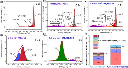
C 1s and K 2p hard X-ray photoelectron spectroscopy spectra of graphite electrodes: (a) pristine, and after 10 cycles in (b) 7 mol kg−1 KFSA/monoglyme (G1) and (c) 0.8 mol dm−3 KPF6/EC:DEC electrolytes. (d) S 1s spectrum in 7 mol kg−1 KFSA/G1 and (e) P 1s spectrum tested in 0.75 mol kg−1 KPF6 EC:DEC. The photoelectron intensities were corrected by relative sensitivity factors42 and normalized by the integrated intensity of the sp2 C peak (284.3 eV) for semi-quantitative analysis. (f) Relative atomic amounts on a graphite electrode cycled in the 7 mol kg−1 KFSA/G1 electrolyte and that in 0.8 mol dm−3 KPF6/EC:DEC. Reproduced from Ref. 34 with permission. Copyright, 2020, The Royal Society of Chemistry.
4.2 KFSA/Diglyme and KFSA/Triglyme Systems
Although the highly concentrated KFSA/monoglyme electrolyte enabled Al passivation and exhibited high Coulombic efficiency in the graphite electrode, monoglyme tended to decompose on high-potential positive electrodes, limiting its use in high-voltage KIBs. Figure 5b and 5c showed that the Coulombic efficiency of the KMnHCF positive electrode was slightly lower than that for the graphite negative electrode.24 To increase the oxidation stability, we utilized long chain glymes such as diglyme and triglyme because longer glymes form stable complexes with K+ ions.43 Previously, Yoshida et al. reported an increase in oxidation stability for glyme molecules upon formation of solvate complexes with Li+ ions due to electron pair donation to Li+ resulting in a lower highest occupied molecular orbital energy level.44 Because a large amount of coordinated glyme molecules are present in highly concentrated electrolytes, the electrolyte achieves higher oxidation stability than conventionally concentrated electrolyte containing free glyme molecules.44 Moreover, electrolytes made from more stable solvate complexes show higher stability toward oxidation,43,45 due to tighter binding between the glyme molecules and the cation. Thus, we also evaluated highly concentrated KFSA/diglyme and KFSA/triglyme solutions.
The solutions of KFSA/monoglyme, KFSA/diglyme, and KFSA/triglyme were prepared with K:O having molalities of 1:10 (∼2.2 mol kg−1) and 1:4 (∼5.6 mol kg−1). The 5.5 mol kg−1 KFSA/monoglyme electrolyte exhibited high ionic conductivity (8.60 mS cm−1) and a relatively low viscosity (20.2 mPa s). In contrast, highly concentrated diglyme and triglyme solutions showed lower ionic conductivities (∼1 mS cm−1) and higher viscosities (>100 mPa s). Nonetheless, the viscosity of these highly concentrated solutions were lower than that of Na counterparts, which would be due to weak Lewis acidity of K+ ions.46
To investigate the solution structures, we utilized Raman spectroscopy. Figure 7a–c show the Raman bands for the glyme molecules showing vibrations for CH2 rocking and C–O–C stretching.34 Pure monoglyme showed two broad peaks near 817 cm−1 and 844 cm−1. In the electrolyte solutions, these peaks decreased in intensity as molality increased. On the other hand, the intensity of the new peaks at 829.5 cm−1 and 854 cm−1 assigned to monoglyme bound to K+ ions increased. Likewise, diglyme and triglyme electrolytes showed a similar change in the intensity of the peaks for free and bound glyme with increasing molality of KFSA. Considering the area fractions of the bound glyme peaks (Figure 7d–e), >70% of the glyme molecules were coordinated to K+ ions in the highly concentrated electrolyte. This change in overall solution structure should aid in preventing oxidation of the glyme molecules.

Normalized Raman spectra of (a) KFSA/monoglyme (G1), (b) KFSA/diglyme (G2), and (c) KFSA/triglyme (G3) solutions between 780–900 cm−1. Comparison of the peak area fraction from deconvoluted Raman spectra with KFSA concentration in the (d) KFSA/G1, (e) KFSA/G2, and (f) KFSA/G3 solutions. Reproduced from Ref. 34 with permission. Copyright, 2020 The Royal Society of Chemistry.
The stability of Al was evaluated electrochemically through voltammetry. First, we confirmed that Al corrosion was negligible in all highly concentrated solutions,34 similar to the highly concentrated KFSA/monoglyme solution. Though the highly concentrated electrolytes were effective at passivating and stabilizing the Al electrode, these electrolytes could potentially be oxidized on a composite electrode, i.e. active materials and conductive carbons. Therefore, we further investigated the oxidation stability by linear sweep voltammetry (LSV) using Ketjen black (KB) electrodes consisting of KB:PVdF = 80:20 (wt%). In the LSV curve (Figure 8a), the 2.2 mol kg−1 KFSA/monoglyme and 2.2 mol kg−1 KFSA/diglyme electrolyte cells exhibited an increase in anodic current from ∼4.3 V vs. K+/K. Increasing to 5.5 mol kg−1 in the KFSA/monoglyme electrolyte did not significantly improve the oxidation stability. In contrast, highly concentrated diglyme and triglyme solutions exhibited higher anodic stability, showing oxidation at potentials higher than ∼4.7 V vs. K+/K. This high anodic stability is caused by the higher stability of the solvate complexes of diglyme and triglyme than that of monoglyme.43,47
![(a) Linear sweep voltammograms of Ketjen black (KB) composite electrodes formed on Al foil in three-electrode cells filled with KFSA in monoglyme (G1), diglyme (G2), and triglyme (G3) electrolytes. Voltammograms of the Al electrode in 5.5 mol kg−1 KFSA/G1 are also shown in (a) (pink line) for comparison. (b) Cycling results for K||K2Mn[Fe(CN)6] cells containing 5.5 mol kg−1 KFSA/G1 (top), 5.6 mol kg−1 KFSA/G2 (middle), and 5.6 mol kg−1 KFSA/G3 electrolytes (bottom). (c) Variations of their Coulombic efficiency. Reproduced from Ref. 34 with permission. Copyright, 2020 The Royal Society of Chemistry.](https://oup.silverchair-cdn.com/oup/backfile/Content_public/Journal/bcsj/95/4/10.1246_bcsj.20210412/3/m_20210412fig08rgb.jpeg?Expires=1748390317&Signature=kNTqAgc1IiX-gYaTcS6OD6ruEyGWE~-ugkS2K2ZgnZ~aDQJz7idjpbY9N1s7g9gZ6DngoegYPOSPDheh8MUE5XPGjDZW2STFdD85pBFwa1uR4ojOYC4PjGo8jxy5Mwz9ABGvuzwmeIDM0NpfL-9BH6uq-mmsI8uAGdtTMnPMpc5gJaIQeAFZNGPQj5DETCejdyp4mCAVwBnOG7FhTM1tHUnIneHLXotFIk-EtNA4yTU4RloJZSpapj5qcHRF-fnwbFU3Q3tDMhFHDPfoCSh~3KBjS~b5a3JmNE7kULOzEzN3VLct6A2pGqmO86GTsbojC9SQLUUz-D3J~CZd3LD7lQ__&Key-Pair-Id=APKAIE5G5CRDK6RD3PGA)
(a) Linear sweep voltammograms of Ketjen black (KB) composite electrodes formed on Al foil in three-electrode cells filled with KFSA in monoglyme (G1), diglyme (G2), and triglyme (G3) electrolytes. Voltammograms of the Al electrode in 5.5 mol kg−1 KFSA/G1 are also shown in (a) (pink line) for comparison. (b) Cycling results for K||K2Mn[Fe(CN)6] cells containing 5.5 mol kg−1 KFSA/G1 (top), 5.6 mol kg−1 KFSA/G2 (middle), and 5.6 mol kg−1 KFSA/G3 electrolytes (bottom). (c) Variations of their Coulombic efficiency. Reproduced from Ref. 34 with permission. Copyright, 2020 The Royal Society of Chemistry.
Since the highly concentrated KFSA/diglyme and KFSA/triglyme solutions achieve higher oxidation stability than KFSA/monoglyme, electrochemical performance of K||KMnHCF cells filled with the highly concentrated solutions were evaluated (Figure 8b). As expected, highly concentrated KFSA/diglyme and KFSA/triglyme cells showed higher Coulombic efficiency of 78 and 87%, respectively, than for 61% in KFSA/monoglyme electrolyte cells. The higher Coulombic efficiency in diglyme and triglyme electrolytes would be due to less electrolyte decomposition. Even in the subsequent cycles, the KFSA/monoglyme cell maintained a low Coulombic efficiency of approximately 90% (Figure 8c), whereas the diglyme and triglyme cells demonstrated higher Coulombic efficiencies of approximately 99% and 99.5%, respectively (Figure 8c). In addition to the KMnHCF positive electrodes, the graphite negative electrodes demonstrated excellent electrochemical performance, almost identical to that of the highly concentrated KFSA/monoglyme electrolyte.34 These results prove stable SEI formation and high reversibility for K+ ion intercalation with graphite when using these KFSA/glyme electrolytes. Thus, the highly concentrated KFSA/triglyme electrolyte with high oxidation stability is a promising electrolyte for high-voltage KIBs.
5. Ionic Liquid Electrolytes
In the previous sections, we described the highly concentrated KFSA electrolytes, which demonstrated wide potential windows, allowed appropriate SEI formation on the graphite electrode, and possessed Al foil passivation ability. In this section, we introduce a KFSA-based IL of K[N(SO2F)]-[N-methyl-N-propylpyrrolidinium][N(SO2F)2], abbreviated as K[FSA]-[C3C1pyrr][FSA]. This was previously developed as a promising IL possessing a wide potential window (5.72 V) and high ionic conductivity (4.8 mS cm−1 at ∼1 mol dm−3).48
By using 1 mol dm−3 K[FSA]-[C3C1pyrr][FSA] electrolyte, graphite electrode delivered much higher Coulombic efficiency than that in a carbonate electrolyte. As shown in the charge–discharge curves (Figure 9a), a large irreversible capacity originating from electrolyte decomposition and SEI formation was observed in both cells in the first cycle. Nonetheless, the IL electrolyte cell showed a higher Coulombic efficiency (65%) than the EC:DEC electrolyte cell (60%). For the IL electrolyte, the initial discharge capacity was 265 mAh g−1, 95% of the theoretical capacity for KC8. In subsequent cycles, the IL electrolyte cell maintained a higher Coulombic efficiency than the EC:DEC electrolyte cell (Figure 9b).
![(a) Charge–discharge profiles during initial cycling (the cycle 1 is shown by a dotted line and cycle 2 by a solid line), (b) cycling performance of graphite/PVdF electrodes, hard X-ray photoelectron spectroscopy spectra of (c) C 1s and (d) N 1s regions for graphite/PVdF electrodes after 1 cycle in cells containing K[FSA]/EC:DEC or K[FSA]/[C3C1pyrr][FSA] where N-methyl-N-propylpyrrolidinium is abbreviated as [C3C1pyrr]. Reproduced from Ref. 35 with permission. Copyright, 2020 American Chemical Society.](https://oup.silverchair-cdn.com/oup/backfile/Content_public/Journal/bcsj/95/4/10.1246_bcsj.20210412/3/m_20210412fig09rgb.jpeg?Expires=1748390317&Signature=y22HeIKa3d9vOjLwPtVdJsF3zTTbJnjGzyRb-qOuIZkzaIbE~Y3biokhYAxkv7-rUqi3TMaPRlN6iF0xns-J7ILmlhpoXPg2qjm2wjvRTnDvWcFXMxrdI7nZFte~R33i2D7Ba3A5ICBqzQ96I~uNqavAy0wNagI6zDA7sF2fsflMri7Slno-FHBNe13dgm4BzcbPJqr8rcG6keGKEzNA0d4BLTDRi9vAAkaliomwX883rFhO1Bxq4WSjcDPet3LwjVaesfLbyvWahvDqisZpQS54jaTjfgnBLhrmtgLBex-Yx709ZEy4bjwFX2rC-5diAgsFChP647ALcT~Mqwx1ng__&Key-Pair-Id=APKAIE5G5CRDK6RD3PGA)
(a) Charge–discharge profiles during initial cycling (the cycle 1 is shown by a dotted line and cycle 2 by a solid line), (b) cycling performance of graphite/PVdF electrodes, hard X-ray photoelectron spectroscopy spectra of (c) C 1s and (d) N 1s regions for graphite/PVdF electrodes after 1 cycle in cells containing K[FSA]/EC:DEC or K[FSA]/[C3C1pyrr][FSA] where N-methyl-N-propylpyrrolidinium is abbreviated as [C3C1pyrr]. Reproduced from Ref. 35 with permission. Copyright, 2020 American Chemical Society.
The chemical components of the surface layer formed in the IL and conventional carbonate electrolyte were compared with HAXPES analysis. Figure 9c shows the C 1s spectra for graphite electrodes after one charge-discharge cycle using 1 mol dm−3 K[FSA] dissolved in [C3C1pyrr][FSA] or EC:DEC. For EC:DEC, peaks forR–C(=O)–R, R–C(=O)–O–R, and R–O–CO–O–R49,50 were observed, indicating deposition of EC and DEC derived decomposition products. Different peaks were observed for the IL electrolyte, including >C=O and –C–N– near 286–287 eV,51 indicating the deposition of [C3C1pyrr] cation and [FSA] anion decomposition products on the graphite electrode.
In the N 1s HAXPES spectra (Figure 9d), graphite electrode tested in EC:DEC electrolyte showed a small peak for –N–SO−.52 The electrode tested in IL electrolyte exhibited two strong peaks for –N–SO− and –C–N+–.52 Decomposition of the [C3C1pyrr] cation leads to this –C–N+– peak. Aside, the S 1s and F 1s spectra indicate deposition of decomposition products originating from both the [C3C1pyrr] cations and [FSA] anions. These results suggest combined decomposition of these two species can lead to a stable SEI. Moreover, the use of PANa and CMC binders instead of PVdF significantly improved the electrochemical performance, especially the Coulombic efficiency and long-term stability. HAXPES results revealed that the SEI growth during cycling observed in the PVdF electrode was suppressed in the CMC and PANa electrodes, indicating decreased electrolyte decomposition during cycling. Consequently, the CMC electrode showed high capacity retention of 94.7% and a high average Coulombic efficiency of 99.7% across 1,000 cycles in a K cell.
To evaluate Al foil stability, cyclic voltammetry was performed in the K[FSA]-based electrolytes. The CV curves (Figure 10a) showed that the anodic current increased from ∼3.5 V with K[FSA]/EC:DEC. In contrast, by using the IL in the K cell, Al corrosion and oxidation of the electrolyte were successfully suppressed up to 6 V (Figure 10b). This could be linked to sufficient passivation of the Al surface by lower solubility species in the IL such as Al[FSA]3.53,54 Based on the Al passivation ability and high anodic stability, KMnHCF composite electrode coated on Al current collector delivered highly reversible charge-discharge reaction. As seen in Figure 10c, the KMnHCF electrode showed higher reversible capacity (133 mAh g−1) in the IL electrolyte than in the KPF6/EC:PC electrolyte (120 mAh g−1). Moreover, the KMnHCF electrode delivered a smaller irreversible capacity in the IL electrolyte (46 mAh g−1) than in the KPF6/EC:PC electrolyte (89 mAh g−1). As a result, IL electrolyte cell showed much higher Coulombic efficiency during cycling (Figure 10d). The lower irreversible capacity and higher Coulombic efficiency in the IL electrolyte would be due to its suppressed decomposition, excellent stability toward oxidation, and ability to effectively passivate the K metal electrode, which prevents continuous electrolyte decomposition on the electrode as well as degradation.
![Cyclic voltammograms at Al foil electrodes in K cells filled with (a) 1 mol dm−3 K[FSA] EC:DEC and (b) 1 mol dm−3 K[FSA]/[C3C1pyrr][FSA] where N-methyl-N-propylpyrrolidinium is abbreviated as [C3C1pyrr]. (c) Charge–discharge curves and (d) resulting Coulombic efficiencies of KMnHCF electrodes in K cells filled with either 1 mol dm−3 K[FSA]/[C3C1pyrr][FSA] or 1 mol dm−3 KPF6 EC:PC. (e) Charge–discharge curves and (f) variations in capacity and efficiency of a graphite||K2Mn[Fe(CN)6] full cell filled with a 1 mol dm−3 K[FSA]/[C3C1pyrr][FSA] IL. For the full cell, a negative/positive capacity ratio of 1 was chosen based on the initial capacities of the negative and positive electrodes. Reproduced from Ref. 35 with permission. Copyright, 2020 American Chemical Society.](https://oup.silverchair-cdn.com/oup/backfile/Content_public/Journal/bcsj/95/4/10.1246_bcsj.20210412/3/m_20210412fig10rgb.jpeg?Expires=1748390317&Signature=kI~csrQIYg9FM5qrroR~O~cdYZb3zkTziHl7ofdMjsOHe~Wp-a2Z4A2D8jUgE034HCErCGen8DZQwd~cwWSgIfHDFnevvlRbZK7FTevKK8ODo~2lv3v9RmlRjLmWdqeEo7918~rnf2XZhtSKgr7rZlngnwTdU4D2FSyZkUbvbJ6mYvQFMr36SfuEQK21rDt4VZZF2W3jnz-WAP2MEMkvtqBLEODDr8sABOmNhk9phxHpUfUzEp2z5LyN5f1FOAyIILKRtZNLyvmyThul2B1IvD5JdsADNn0UDB-5kOtVBjvfhhsDBrPHp0t1GaIId5aABfgloWXiPgG6FzMIFsbpUw__&Key-Pair-Id=APKAIE5G5CRDK6RD3PGA)
Cyclic voltammograms at Al foil electrodes in K cells filled with (a) 1 mol dm−3 K[FSA] EC:DEC and (b) 1 mol dm−3 K[FSA]/[C3C1pyrr][FSA] where N-methyl-N-propylpyrrolidinium is abbreviated as [C3C1pyrr]. (c) Charge–discharge curves and (d) resulting Coulombic efficiencies of KMnHCF electrodes in K cells filled with either 1 mol dm−3 K[FSA]/[C3C1pyrr][FSA] or 1 mol dm−3 KPF6 EC:PC. (e) Charge–discharge curves and (f) variations in capacity and efficiency of a graphite||K2Mn[Fe(CN)6] full cell filled with a 1 mol dm−3 K[FSA]/[C3C1pyrr][FSA] IL. For the full cell, a negative/positive capacity ratio of 1 was chosen based on the initial capacities of the negative and positive electrodes. Reproduced from Ref. 35 with permission. Copyright, 2020 American Chemical Society.
Since both KMnHCF and graphite electrodes achieved excellent reversibility in the half-cells filled with the IL electrolyte, we assembled a KMnHCF||graphite full cell containing 1 mol dm−3 K[FSA]/[C3C1pyrr][FSA] IL. However, the full cell without any pretreatment delivered a large irreversible capacity at approximately 3 V due to electrolyte decomposition at the negative electrode surface,35 which was confirmed using a three-electrode cell. As a result, the initial discharge capacity was 43 mAh (g-positive)−1, which was less than half of the designed capacity. A larger irreversible capacity in the full cell than in the half-cell was also observed in the highly concentrated KFSA/glyme electrolytes.24,34 To suppress the initial irreversible capacity in the full cell, we found two effective methods: 1) the use of electrolyte additives such as VC34 and 2) pretreatment of the electrolyte with K metal,24,35 by soaking a K metal disk (15 mm diameter) in 300 µL of the electrolyte for several days. Indeed, the irreversible capacity of approximately 3 V was decreased through pretreatment resulting in a major improvement in the Coulombic efficiency from 24% to 58%. We deduced that a small amount of FSA− anions in the electrolytes decomposed when contacting the K metal and thereafter the products dissolved into the electrolytes. The decomposition products act as a film-forming additive in the full cell. Further analysis of the reactions occurring during pretreatment is ongoing and the results will be reported elsewhere.
During the first cycle, the KMnHCF||graphite full cell using the pretreated 1 mol dm−3 K[FSA]/[C3C1pyrr][FSA] delivered a discharge capacity of 91 mAh g−1 based on the KMnHCF mass and an average discharge voltage of 3.2 V (Figure 10e and 10f). The additional passivation capability of the pretreated IL-based electrolyte resulted in stable cycling across 200 cycles with a capacity retention of 76% and an average Coulombic efficiency of 99.5%. The higher Coulombic efficiency is the reason for the higher cycling performance than that of KIB which has been previously reported.28,55,56
6. Binary Salt Electrolytes
The previous sections discussed how highly concentrated KFSA/glyme and IL electrolytes achieve Al passivation, high oxidation stability, and stable SEI formation derived from FSA− anion decomposition products on the graphite electrode. Nevertheless, KPF6 salts still have some advantages, such as low cost and passivation of the Al current collector over a wide concentration range due to the formation of AlF3 as a stable passivation layer on the Al surface.37 Indeed, KPF6/carbonate ester electrolytes are the most common electrolyte group for KIBs as shown in Figure 1. However, during initial cycling the KIBs with the KPF6 electrolytes frequently showed low Coulombic efficiency and a decaying capacity as described above.22,24,55 The low Coulombic efficiency is linked to insufficient passivation of negative electrodes derived from a partly soluble SEI in the KPF6 electrolyte.23,29,57 One way to take advantage of both KPF6 and KFSA salts is the use of KPF6-KFSA binary salt electrolytes. In this section, we review our study on the development of KPF6-KFSA binary salt electrolytes, including the role of the KPF6/KFSA ratio and solvent in determining the electrolyte physical properties, corrosion of Al current collectors, and the electrochemical properties with KMnHCF and graphite electrodes.
First, we prepared combinations of KPF6-KFSA/EC:DEC solutions at 0.5–1 mol kg−1 K+ ion concentrations with different PF6−:FSA− ratios. Nevertheless, KPF6 rich solutions of 1.0 mol kg−1 KPF6 and 1.0 mol kg−1 K(PF6)0.9(FSA)0.1 in EC:DEC exhibited salt precipitation at 25 °C due to the limited solubility of KPF6.24 Figure 11a shows ionic conductivity of KPF6-KFSA solutions at 25 °C after saturation and removal of precipitates. KPF6-KFSA solutions showed ionic conductivities (8–9 mS cm−1) between pure KPF6 (∼8 mS cm−1) and KFSA (∼11 mS cm−1) electrolytes, while higher KFSA ratios and higher concentrations increased the ionic conductivities. The high ionic conductivity of KFSA-rich solutions is attributed to weaker Coulombic interactions between FSA− and K+ compared with PF6−, resulting in greater dissociation.57,58 Moreover, all the electrolytes showed a much lower viscosity (3–5 mPa·s) than that of the 7 mol kg−1 KFSA/monoglyme (47 mPa·s)24 or K[FSA]/[C3C1pyrr]FSA ILs (78 mPa·s);48 and were comparable to practical 1.0 mol dm−3 LiPF6/EC:DEC.59 Thus, the ionic conductivities and viscosities of the KPF6-KFSA binary salt solutions are promising for application as electrolytes within KIBs.
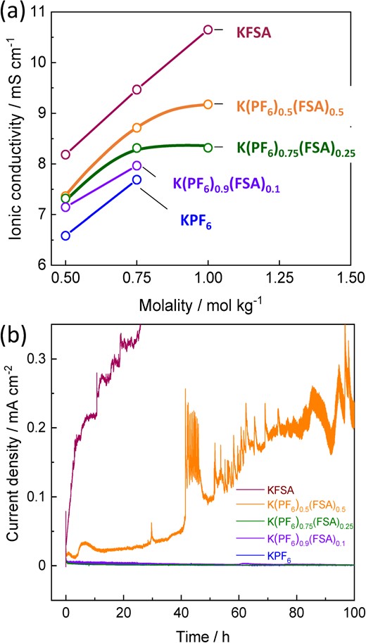
(a) Ionic conductivity plots as a function of concentration for KPF6, K(PF6)0.9(FSA)0.1, K(PF6)0.75(FSA)0.25, K(PF6)0.5(FSA)0.5, and KFSA/EC:DEC solutions at 25 °C. (b) Chronoamperograms of Al foil electrodes in 0.75 mol kg−1 KPF6, 0.75 mol kg−1 K(PF6)0.9(FSA)0.1, 1 mol kg−1 K(PF6)0.75(FSA)0.25, 1 mol kg−1 K(PF6)0.5(FSA)0.5, and 1 mol kg−1 KFSA/EC:DEC electrolytes at 4.6 V vs. K+/K. Reproduced from Ref. 26 with permission. Copyright, 2020 American Chemical Society.
To evaluate the Al corrosion behavior at high potentials, we tested Al foil working electrodes by applying a constant potential at 4.6 V vs. K+/K in KFSA, K(PF6)0.5(FSA)0.5, K(PF6)0.75(FSA)0.25, K(PF6)0.9(FSA)0.1, and KPF6 electrolyte solutions. A significant anodic current was observed in the KFSA and K(PF6)0.5(FSA)0.5 electrolyte solutions (Figure 11b). We also confirmed the numerous pits on the Al foil surface, indicating the Al pitting in the KFSA and K(PF6)0.5(FSA)0.5 electrolytes. In the case of K(PF6)0.75(FSA)0.25, K(PF6)0.9(FSA)0.1, and KPF6 electrolytes, a negligible anodic current flowed (Figure 11b). Moreover, the Al electrodes in these electrolytes retained their smooth surface morphology without pit formation. These results showed the binary-salt EC:DEC electrolytes with KPF6/KFSA molar ratios higher than 3 (0.75/0.25) possess enough passivation ability on the Al current collector at high potential region. The passivation should be due to formation of AlF3 layer working as a passivation layer on the Al surface just as in KPF6/EC:PC electrolytes.60
In addition to the passivation ability, K(PF6)0.75(FSA)0.25 and K(PF6)0.9(FSA)0.1 enabled the good electrochemical performance of KMnHCF positive electrodes on an Al current collector. Figure 12 shows the charge–discharge properties of KMnHCF electrodes in the K(PF6)0.75(FSA)0.25, K(PF6)0.9(FSA)0.1, and KPF6 electrolyte cells. These KMnHCF cells displayed an almost identical reversible capacity. During cycling, all cells showed high Coulombic efficiency of ca. 95%. (Figure 12d). These results confirm that the K(PF6)0.75(FSA)0.25, K(PF6)0.9(FSA)0.1, and KPF6 solutions possess sufficient stability toward oxidation up to 4.3 V vs. K+/K and high compatibility with KMnHCF electrodes.
![Charge–discharge curves of K2Mn[Fe(CN)6] electrodes in three-electrode cells containing (a) 1.0 mol kg−1 K(PF6)0.75(FSA)0.25, (b) 0.75 mol kg−1 K(PF6)0.9(FSA)0.1, and (c) 0.75 mol kg−1 KPF6 EC:DEC electrolytes. (d) Coulombic efficiencies of each electrolyte during cycling. The current density was maintained at 15.5 mA g−1 for charge and discharge. Reproduced from Ref. 26 with permission. Copyright, 2020 American Chemical Society.](https://oup.silverchair-cdn.com/oup/backfile/Content_public/Journal/bcsj/95/4/10.1246_bcsj.20210412/3/m_20210412fig12rgb.jpeg?Expires=1748390317&Signature=IJy3R8ijvX1Lov07oy4EcppjFm5FwbDvEgQg8q9uMpE9YtssYWD2D9y5oEywE8gbq0p6m7uQbuYS5ng8zxW6K25dZSPr4mg5kx7Z8CeXXLSUBpog0D-uABrKsP4Zl22IwWKgUfmH-3ZK9YIWkCZOAWyfnJAVBRvnjSSLXGSqoAzVArwDuvvNUseue0eDK2eA9XvwYaa6I~8LKl-7X8AUEr8t0u0kjOebJxNJCI4noqHuhgVKg2eBURMYkl7ORHs4aiL2XyDmi-xzP8h7i5cZRtUbiA~udJu9b9SEqLwjCqTIB7vuePD3Ya69ekjjCTpMumgMgcegrPmNbGcHXSjA5Q__&Key-Pair-Id=APKAIE5G5CRDK6RD3PGA)
Charge–discharge curves of K2Mn[Fe(CN)6] electrodes in three-electrode cells containing (a) 1.0 mol kg−1 K(PF6)0.75(FSA)0.25, (b) 0.75 mol kg−1 K(PF6)0.9(FSA)0.1, and (c) 0.75 mol kg−1 KPF6 EC:DEC electrolytes. (d) Coulombic efficiencies of each electrolyte during cycling. The current density was maintained at 15.5 mA g−1 for charge and discharge. Reproduced from Ref. 26 with permission. Copyright, 2020 American Chemical Society.
We also evaluated the electrochemical performance of the binary salt electrolytes with graphite electrodes in the K||graphite cells filled with KFSA, K(PF6)0.75(FSA)0.25, K(PF6)0.9(FSA)0.1, and KPF6 electrolytes. These cells exhibited reversible capacities of ∼270 mAh g−1, high capacity retention, and negligible capacity fading during cycling (Figure 13a, b). On the other hand, remarkable differences were observed in their irreversible capacities and Coulombic efficiencies. The KPF6 electrolyte exhibited a large irreversible capacity and a low Coulombic efficiency (80%) at the initial cycle (Figure 13a), whereas the K(PF6)0.75(FSA)0.25 and K(PF6)0.9(FSA)0.1 cells displayed considerably lower irreversible capacities and, consequently, higher Coulombic efficiencies close to 90%. During subsequent cycles, the binary salts’ Coulombic efficiencies approached 99.5%, which is higher than that of the KPF6 electrolyte (approximately 98%–99%), as shown in Figure 13b. Thus, the addition of KFSA into the KPF6 system seemingly improved the SEI stability and minimized irreversible reactions. Moreover, the graphite electrode exhibited higher rate capability in the binary-salt electrolytes than in the KPF6 electrolyte. The high Coulombic efficiency and improved rate performance were enabled through an improved SEI which formed in the binary salt system, showing higher K+ conduction and more efficient passivation.
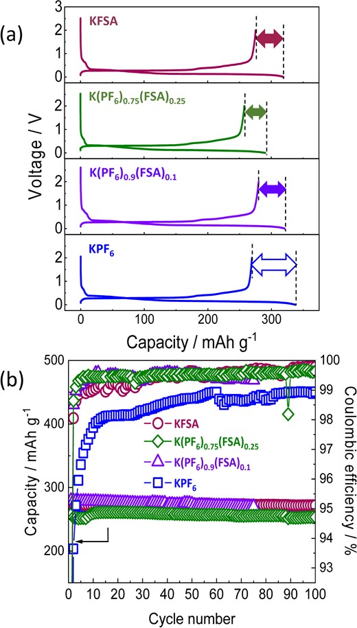
(a) First cycle charge–discharge curves of graphite electrodes in K cells containing 1.0 mol kg−1 KFSA (red line), 1.0 mol kg−1 K(PF6)0.75(FSA)0.25 (green line), 0.75 mol kg−1 K(PF6)0.9(FSA)0.1 (purple line), or 0.75 mol kg−1 KPF6 (blue line) in EC:DEC. (b) Reversible capacities and Coulombic efficiencies during cycling. Current densities were maintained at 25 mA g−1 during cycling. Reproduced from Ref. 26 with permission. Copyright, 2020 American Chemical Society.
To prove the impact of KFSA on the surface chemistry, we conducted HAXPES analysis of the graphite electrodes cycled in the K(PF6)0.9(FSA)0.1 and KPF6 electrolytes. HAXPES analyses indicated that the SEI’s main components consisted of C, O, K, and F in the K(PF6)0.9(FSA)0.1 and KPF6 electrolytes. However, the K(PF6)0.9(FSA)0.1 SEI showed more relative K content compared to KPF6, while the amounts of C, O, and especially F were lower.26 This result indicates a change in the SEI composition when adding FSA to the electrolyte. Furthermore, the total atomic ratio of the sp2 carbons on the graphite surface in the K(PF6)0.9(FSA)0.1 electrolyte was decreased to ∼80% of that in the KPF6 electrolyte, suggesting the formation of a thinner SEI layer on the graphite surface cycled in the KPF6-KFSA electrolyte.
Since the solvent has a significant effect on the electrochemical performance of the positive and negative electrodes,22,61 we evaluated the electrochemical performance of 1.0 mol kg−1 K(PF6)0.9(FSA)0.1 in EC:PC, EC:EMC, and EC:DEC. In these electrolytes, KMnHCF positive electrodes exhibited a similarly high reversible capacity (∼130 mAh g−1) during their first cycle and good capacity retention across 20 cycles. Notably, the EC:PC electrolyte cell delivered a higher Coulombic efficiency than the other electrolytes. In contrast, measurements on K||graphite cells in each solvent showed no significant difference. All K||graphite cells delivered a reversible capacity of ∼270 mAh g−1 with Coulombic efficiency of ∼87% at the initial cycle and high Coulombic efficiencies (99.5%) in the subsequent cycles. These results indicated that stable and superior SEIs were formed on the graphite electrodes in the K(PF6)0.9(FSA)0.1/EC:PC and EC:EMC electrolyte as well as in the K(PF6)0.9(FSA)0.1/EC:DEC one.
Lastly, graphite||KMnHCF full cells were tested with the electrolytes. Figure 14a shows charge–discharge curves of the full cell with KPF6/EC:DEC, K(PF6)0.75(FSA)0.25/EC:DEC, and K(PF6)0.75(FSA)0.25/EC:PC electrolytes during the first cycle. Based on these results, the K-ion cell with K(PF6)0.75(FSA)0.25/EC:PC displayed the highest initial Coulombic efficiency (72.5%), decreased polarization, and a reasonable reversible capacity of 105 mAh g−1.
![(a) Charge–discharge curves of the first cycle for graphite||K2Mn[Fe(CN)6] full cells containing 0.75 mol kg−1 KPF6/EC:DEC, 1.0 mol kg−1 K(PF6)0.75(FSA)0.25/EC:DEC, or 1.0 mol kg−1 K(PF6)0.75(FSA)0.25/EC:PC. (b) Coulombic efficiencies and (c) capacity retention during cycling of each cell. The current density was maintained at 15.5 mA (g-positive)−1 for cycles 1–5 then increased to 155 mA (g-positive)−1 for cycles 6–500. Reproduced from Ref. 26 with permission. Copyright, 2020 American Chemical Society.](https://oup.silverchair-cdn.com/oup/backfile/Content_public/Journal/bcsj/95/4/10.1246_bcsj.20210412/3/m_20210412fig14rgb.jpeg?Expires=1748390317&Signature=jXnj05Axbwb92frCUQoZF5OVEKGvf7abou3n4LzGBI3EJaZWuJ3ZiQU3q6TC3JRBW~E4VhbaFsO8KJrIzh~S68Zjbont6sE4-avq5MgXc-ZRy4VCFN3tUSHYJgGgnlK2v56xwtvFocXuzBkQJ2UQ6hNBK-imv6NraTUdUnsNOVWLIcj4i5gYsqdz1QxtFFsggX3w7oDkCWV7z~cEAmApSa6VWTGEL1vNsXpcfQ--X7uBaZLaj1vZiAuGnUvUxuxdpI0UymjPNPRromNOxXQt5VdVrBFo8P976pivCH1-ZmJm2xDbiI0JIpWAUZlBrVxBtFIbD475n2v94Xi~DZCtOA__&Key-Pair-Id=APKAIE5G5CRDK6RD3PGA)
(a) Charge–discharge curves of the first cycle for graphite||K2Mn[Fe(CN)6] full cells containing 0.75 mol kg−1 KPF6/EC:DEC, 1.0 mol kg−1 K(PF6)0.75(FSA)0.25/EC:DEC, or 1.0 mol kg−1 K(PF6)0.75(FSA)0.25/EC:PC. (b) Coulombic efficiencies and (c) capacity retention during cycling of each cell. The current density was maintained at 15.5 mA (g-positive)−1 for cycles 1–5 then increased to 155 mA (g-positive)−1 for cycles 6–500. Reproduced from Ref. 26 with permission. Copyright, 2020 American Chemical Society.
Figure 14b and 14c display the Coulombic efficiencies and discharge capacity retention over 500 cycles. Both KPF6-KFSA cells showed improved Coulombic efficiencies during cycling over the KPF6 electrolyte cell (Figure 14b). In particular, the K(PF6)0.75(FSA)0.25/EC:PC cell displayed the highest stability and Coulombic efficiency, reaching 99.8% after 100 charge-discharge cycles. In addition, the K(PF6)0.75(FSA)0.25/EC:DEC and K(PF6)0.75(FSA)0.25/EC:PC cells showed reversible capacities of 72% and 75% after 500 cycles (Figure 14c), respectively. Much higher capacity retention than that of KPF6 cell (37%) after the same number of cycles. It is worth noting that these full cells were not subjected to any electrolyte pretreatment or pre-cycling and electrolyte additives were not used, demonstrating the promising properties of the binary salt electrolytes for advanced KIBs. To further improve the cycle life of KIBs, we are developing new electrolyte additives.62
7. Perspectives
We have described the effects of electrolyte salt, solvent, and concentration on electrolyte properties such as ionic conductivity, oxidation stability, and SEI formation ability on negative electrodes. KPF6 and KFSA can be used as electrolyte salts because of their sufficient solubility in aprotic solvents and their electrochemical stability. KFSA is highly soluble; however, KFSA electrolytes were mostly corrosive to Al foil current collectors, except in highly concentrated solutions and ILs. Highly concentrated KFSA/glyme or KFSA-based IL electrolytes showed high oxidation stability and high efficiency toward the passivation of the Al current collector and stable SEI formation on the negative electrodes. HAXPES revealed SEIs were thinner when formed in the 7 mol kg−1 KFSA/monoglyme and 1 mol dm−3 K[FSA]/[C3C1pyrr][FSA] electrolytes compared to those formed in the conventional KPF6 electrolyte. In the SEI structure, they contained electrolyte decomposition products from the FSA− anion. Although graphite electrodes exhibited excellent reversibility and high Coulombic efficiencies in the KFSA electrolytes, the irreversible capacity of the full cell, which mainly arises from the graphite negative electrode, was larger than that of the half-cell. We theorize that the K metal applied as the counter electrode for the half-cells quickly reacted with the FSA− anion in the electrolyte after assembling the cell, and the decomposition products dissolved in the electrolyte and acted as film-forming additives. Future work will clarify the dissolved chemicals formed via the reaction between the K metal and electrolytes.
In contrast, the KPF6 salt dissolved in the carbonate ester or glyme solvents up to ∼1 mol kg−1. Although the KPF6 electrolyte typically formed an unstable SEI on the negative electrodes in KIBs, the KPF6-KFSA binary salt electrolyte allow both Al passivation and suitable SEI formation. The optimized electrolyte of K(PF6)0.75(FSA)0.25/EC:PC prepared without any pretreatment or use of additives demonstrates higher Coulombic efficiency and considerably higher cycling performance in a 4 V-class K-ion full cell than the conventional KPF6. The formation of an anion-based SEI was initially reported in highly concentrated LiTFSA and LiFSA electrolytes. However, the study on KPF6-KFSA electrolytes demonstrated a remarkable effect of KFSA addition on stabilizing SEI even when the concentration of KFSA was low, unlike LIBs. Because the binary salt electrolytes contain EC, the EC-based SEI should be formed at a higher voltage than the FSA-based SEI. The formation of an incomplete EC-based passivation film at higher potentials may induce further decomposition of the FSA− anions at lower potentials and the formation of an FSA-based SEI. Future research will reveal the mechanism of FSA− anion decomposition in different electrolytes and cell systems. Overall, the formation of a stable SEI is a more critical challenge in KIBs than in LIBs; one possible solution is the formation of an SEI containing an anion-derived component. Another solution is the development of effective electrolyte additives to further improve the cycle life of 4 V-class KIBs. Although KIBs showed high operating voltages similar to LIBs, previous studies have highlighted that the electrolyte solution and surface chemistry are different from those of LIBs. Therefore, establishing a distinct design strategy for KIB electrolytes from LIB electrolytes is essential.
The non-aqueous electrolytes have been developed to realize high-voltage and long-life KIBs, whereas we should also evaluate and improve the rate performance, cost-efficiency, and safety of KIB electrolytes for practical use. Although KIBs are expected to have a high-rate performance compared to LIB and SIB, the high-rate performance of KIB has not been fully demonstrated so far. As the rate performance of graphite electrodes was significantly better in highly concentrated KFSA/monoglyme electrolytes than the KPF6/carbonate electrolytes, the development of electrolytes that maximize the rate performance of KIBs is also essential in demonstrating their advantages over LIBs and NIBs. In terms of electrolyte costs, KPF6-based electrolyte is highly desirable over the highly concentrated KFSA and ionic liquid electrolytes. Thus, the addition of a small amount of KFSA or other electrolyte additives into KPF6-based electrolytes would be the most practical strategy for KIBs. The safety concern is one of the main challenges for large-scale KIBs since highly reactive K metal will be deposited when KIBs are overcharged. Future studies should evaluate the safety of KIBs in comparison to LIBs and NIBs. In order to solve the safety issues, electrolytes passivating K metal and flame-retardant electrolytes are essential. Thus, the development of new electrolytes will be crucial to the commercialization of KIBs in the 2020s, following the commercialization of NIBs—which was announced by CATL in July 2021.
Acknowledgment
The authors would like to thank Dr. Kei Kubota, Dr. Ryoichi Tatara, Dr. Zachary T. Gossage, Dr. Satoshi Ysuno, Mr. Hiroo Onuma, Ms. Haruka Kojima, Mr. Taiga Fukabori, and Mr. Tatsuo Matsuyama for their experimental support and fruitful discussion. This study was partly funded by the MEXT program “ESICB”; A-STEP program (#JPMJTS1611); CONCERT-Japan program, Japan Science and Technology Agency (JST); and JSPS KAKENHI Grant Numbers No. JP18K14327, JP20J13077, JP20H02849, and JP21K20561. The synchrotron radiation experiments were performed at the BL46XU of SPring-8 as a Priority Research Proposal (priority field: Industrial Application) with the approval of the JASRI (proposal no. 2018B1613).
References

Tomooki Hosaka
Tomooki Hosaka is an assistant professor at Tokyo University of Science. He received his Ph.D. degree from Tokyo University of Science in 2021. He has been a project assistant professor of the Elements Strategy Initiative for Catalysts and Batteries (ESICB) at Kyoto University since 2021. His research focuses on electrode materials and electrolytes for Na- and K-ion batteries.

Shinichi Komaba
Shinichi Komaba is a professor in the Department of Applied Chemistry at Tokyo University of Science. He received his Ph.D. degree in Engineering from Waseda University in 1998 and then was a research associate at Iwate University from 1998 to 2005. From 2003 to 2004, he worked at Institut de Chimie de la Matière Condensée de Bordeaux, France, as a postdoctoral researcher. He joined the Tokyo University of Science as a faculty member in 2005. His current research focuses on materials science and electrochemistry in electrochemical devices (Li-, Na-, and K-ion batteries, biofuel cells, capacitors, and sensors).
