


Abstract
Legged robots are constantly evolving, and energy efficiency is a major driving factor in their design. However, combining mechanism efficiency and trajectory planning can be challenging. This work proposes a computational optimization framework for optimizing leg design during basic walking while maximizing energy efficiency. We generalize the robotic limb design as a four-bar linkage-based design pool and optimize the leg using an evolutionary algorithm. The leg configuration and design parameters are optimized based on user-defined objective functions. Our framework was validated by comparing it to measured data on our prototype quadruped robot for forward trotting. The Bennett robotic leg was advantageous for omni-directional locomotion with enhanced energy efficiency.
Proposed a parametric design of overconstrained robotic limbs with generalized morphology.
Developed a computational design framework for overconstrained robotic limbs by optimizing energy-related metrics.
Validated the energy efficiency metrics with the similar trend using a reconfigurable quadruped prototype.
Benchmarked the energy efficiency in simulated basic tasks for various overconstrained robotic limbs.
Empirically validated the superior walking of Bennett robotic limbs in omni-directional locomotion.
1. Introduction
Energy efficiency has been a driving factor in the evolutionary design of biological structures (Alexander, 1984; Maitra & Dill, 2015; Sharbafi & Seyfarth, 2017), providing a rich source of design inspiration for robots aiming at exceptional performances such as agile locomotion (Roy & Pratihar, 2012) among legged robots (Biswal & Mohanty, 2021). Earlier research on the energy efficiency design of legged robots mainly focused on energy-based indices [e.g., cost of transport (COT) and absolute mechanical energy (Silva & Machado, 2012)] and mimicking the energy-efficient gait pattern from nature (Hoyt et al., 2006; Xi et al., 2016). Recent research shows a converging design pattern with negligible limb inertia (Zhong et al., 2019). A widely adopted approach is to use classical mechanisms, such as four-bar linkages or timing belts, in the robotic limbs so that the designers can arrange the actuators closer to the body frames for a reduced energy cost during agile locomotion (He & Gao, 2020). Examples include the MIT Cheetah 3 (Bledt et al., 2018), ETH SpaceBok (Arm et al., 2019), Stanford doggo (Kau et al., 2019), and ATRIAS (Hubicki et al., 2016). The design problem becomes more challenging when considering the parametric choices, such as leg configurations, link parameters, and transmission radio with ambiguous trade-offs (Chadwick et al., 2020) against optimization for task-specific performances, such as energy efficiency, which is virtually intractable (Ha et al., 2018b).
The numerical approach provides an alternative solution to robot design optimization (Papalambros & Wilde, 2000). One can resolve the design problem by optimizing a task-based performance metric, which has received considerable attention in manipulator design for both serial (Paredis & Khosla, 1991; Ceccarelli & Lanni, 2004; Van Henten et al., 2009) and parallel types (Kim & Ryu, 2003; Collard et al., 2005; Yun & Li, 2011). Likewise, researchers also investigated the task-based optimal design on legged robots (Wollherr et al., 2002; Yesilevskiy et al., 2018; Dinev et al., 2022). Fadini et al. (2021) proposed a computational framework to obtain an energy-efficient monoped robot for the jumping task by optimizing its size and actuators. While these approaches lead to optimal solutions, the resulting designs remain limited due to the design assumptions [e.g., simplification to 2D (Ha et al., 2016) or monoped case], avoidance of discrete parameter (e.g., leg configurations), and limited expansibility to multi-tasks optimization scenario (Chadwick et al., 2020). This study aims to develop a computational design model that simultaneously optimizes the leg configurations and link parameters while quantitatively evaluating the energy efficiency of quadruped robots in locomotion.
1.1 Kinematic generalization of robotic limbs
The mechanical and mechanism designs determine the primitive motor functions of the robotic system, such as versatility, agility, and mechanical efficiency (He & Gao, 2020). As shown in Fig. 1, the design of robotic limbs adopts kinematic chains with serial, parallel, or hybrid configurations. The serial chains generally have a larger workspace and higher agility, such as ANYmal (Hutter et al., 2016). The parallel ones have better performance in structural stiffness and payload capacity (Pandilov & Dukovski, 2014), such as GOAT (Kalouche, 2017). The hybrid design with serial and parallel chains leverages advantages from both sides, making it a potential solution for a balanced design trade-off (Seok et al., 2013; Arm et al., 2019; Ding et al., 2021).
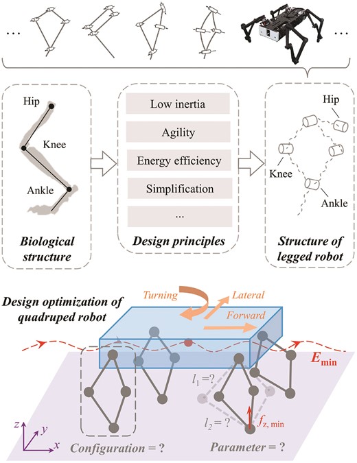
A graphical representation of the robotic limb design optimization problem. After generalizing the design principles of the robotic limbs, one of the research questions is how to obtain the optimal leg design for given basic tasks and robot model parameters towards minimizing energy costs.
Minimizing the leg inertia is also a major design factor to simplify the dynamic model with improved trajectory tracking performance (He & Gao, 2015). Three motors usually actuate each limb, all mounted on each corner of the body frame, including one for rotation in the frontal plane, and two for actuating a limb mechanism in the sagittal plane, supporting limb movement in 3D. A coaxial motor arrangement is widely adopted for a compact form factor driving a planar four-bar linkage, including the MIT Cheetah (Seok et al., 2013), Panther (Ding et al., 2021), and SpaceBok (Arm et al., 2019), or its variants using chain or belt transmissions (Bledt et al., 2018; Katz et al., 2019). In this way, one motor directly drives the hip joint while the other drives the knee joint remotely through the linkage transmission. Such a coaxial arrangement is kinematically equivalent to a five-bar linkage with a zero-length base link or a four-bar linkage with a moving base (Gu et al., 2022). It is also a bio-inspired solution that mimics the kinematics of the mammalian limb, making it a widely used design for robotic limbs in legged robots (Witte et al., 2000). Recently, for developing the energy-efficient dynamic locomotion controller, Ruppert & Badri-Spröwitz (2022) also leveraged quadruped hardware with the linkage-based robotic limb.
The kinematic generalization of a robotic limb is equivalent to the design generalization of a four-bar linkage, which is not limited to the 2D planar motion but extends to the 3D space (Feng et al., 2021). Besides the planar four-bar with parallel axis and non-zero link length, we also have the Bennett linkages with non-parallel joint axes (Baker, 1979) and the spherical linkage with intersecting joint axes and zero link lengths (Chiang, 1984). While the planar design is widely adopted for its simplicity in kinematic formulation, other design choices, such as the Bennett and spherical linkages, expand the design pool to alternative solutions less explored in legged robots (Gu et al., 2022). Recent literature reports a large design pool of the linkage-based robotic limb (He & Gao, 2020), proven practical in existing quadruped robots in Table 1. In summary, there remains a research gap in a generalized guideline for optimizing robotic limb kinematics, which is yet to be explored in the existing literature.
A brief list of recent quadruped robots in the literature. The corresponding basic limb mechanisms are classified, in which only rigid elements are considered.
| Robot design | Limb mechanism |
|---|---|
| Stanford doggo (Kau et al., 2019) | Four-bar linkage |
| Panther (Ding et al., 2021) | Four-bar linkage |
| SpaceBok (Arm et al., 2019) | Four-bar linkage |
| MIT cheetah (Seok et al., 2013) | Four-bar linkage |
| MIT cheetah 2 (Park et al., 2017) | Four-bar linkage |
| MIT cheetah 3 (Bledt et al., 2018) | Chain drive |
| Mini-cheetah (Katz et al., 2019) | Timing belt |
| Unitree A1 (Unitree Robotics, 2023) | Four-bar linkage |
| ANYmal (Hutter et al., 2016) | Direct drive |
| GOAT (Kalouche, 2017) | Parallel mechanism |
| StarlETH (Hutter et al., 2012) | Chain drive |
| SPOT (Moreda et al., 2016) | Four-bar linkage |
| Cheetah-cub (Spröwitz et al., 2013) | Four-bar linkage |
| Minitaur (Kenneally et al., 2016) | Four-bar linkage |
1.2 Computational optimization of robotic limbs
The design challenge for the computational optimization of robotic limbs is to search the optimal design parameters with ambiguous trade-offs, including carefully considering the complexity, energy efficiency, agility, and versatility, as shown in Fig. 1. Bio-inspiration has been proven effective in reducing the design space in both morphology and parametric search, including Salamandra robotica II (Crespi et al., 2013), MIT Cheetah (Seok et al., 2013; Park et al., 2017; Bledt et al., 2018), StarlETH (Hutter et al., 2012), and ANYmal (Hutter et al., 2016). These designs are also limited by the availability of actuators and sensors during the design optimization process (Klute et al., 2002).
On the other hand, some researchers proposed the kinematic indices, such as manipulability and condition number, to intuitively quantify the robot’s performances (Olds, 2015; Hussain et al., 2021). Optimizing the global conditioning indices over the robot’s workspace allows the designers to obtain the optimal designs with maximum workspace and average force production (Kalouche, 2017; Lee et al., 2021). Other performance criteria, such as the accumulative joint torque, maximum joint velocity, and mechanical energy consumption (Chadwick et al., 2020), are also utilized to optimize the robot morphology for a given task. However, these performance criteria are highly task-specific, making it difficult to evaluate the performance of robotic designs quantitatively.
The computational optimization approach solves the problem by modeling the engineering problem mathematically and resolving the optimal solution numerically (Aalae et al., 2016; Lakkanna et al., 2016; Chen et al., 2022; Wang et al., 2023). Since Sims’ Virtual Creatures (Sims, 1994) and Watson’s Embodied Evolution (Watson et al., 2002), the genetic algorithm (GA) has been widely used in the robotic design optimization due to its feasibility of discrete changes (Koza, 1995; Wortmann, 2019). The Covariance Matrix Adaptation – Evolution Strategy (CMA-ES; Hansen et al., 2003) is a widely used approach in robot design, including developing legged creatures (Wampler & Popović, 2009), enhancing the performance of quadruped robots (Digumarti et al., 2014), and optimizing legs, gaits, and control parameters (Silva, 2012; Ha et al., 2016; Chadwick et al., 2020). The CMA-ES approach also addresses the drawbacks of the GAs, such as the limited guarantee of optimality and poor repeatability, by appropriately scaling the inputs and selecting the population size and number of generations to a certain level (Chadwick et al., 2020).
Gradient-based optimization approaches have also been proposed for optimizing the trajectory and leg design (Mombaur, 2009; Dinev et al., 2022). Ha et al. (2016) utilized the implicit function theorem to obtain the relationship between the design and motion parameters, which provided faster convergence and deeper insight into the design principle. However, it can handle the optimization problem with only continuous design parameters (e.g., link lengths, joint torque), which poses a problem when dealing with critical discrete variables (e.g., leg configurations).
Alternatively, the robotic limb design optimization can be formulated as a graph generation problem under the graph grammar and components library (Zhao et al., 2020a). Ha et al. (2018a) formulated the robotic optimization as a shortest path problem and used a combination of modular components to constitute the optimal solution for motion tracking tasks. Many recent approaches also use deep learning tools for optimization design, which have been proven suitable for co-optimizing the robot design and controller (Schaff et al., 2019), demonstrating the potential to generate modified performance. Acquiring large datasets for the learning algorithm (Isakhani et al., 2021) is also computationally expensive. Moreover, the Sim2Real gap might degrade the performance of the policies when transferring the models into real robots (Zhao et al., 2020b).
1.3 Contributions and paper outline
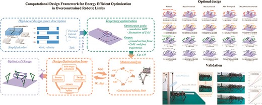
This study presents a computational design method for robotic limbs of quadrupeds aiming at an energy-efficient optimization in gait planning (see Fig. 2). We begin by generalizing the kinematics of robotic limbs using the overconstrained design of a four-bar linkage. The representative design pool generated includes robotic limbs with planar, serial, Bennett, and spherical configurations, as shown in Fig. 3. Next, we formulate the computational optimization problem using a derivative-free approach to incorporate the robot’s energy efficiency during forward, lateral, and turning tasks. Finally, we conducted experiments through reconfigurable quadruped hardware with replacement limbs and verified the effectiveness of the proposed method. Contrary to common practice, we found computational design evidence that the overconstrained limb design using the Bennett linkages shows more efficient energy consumption during lateral and turning tasks while being competitive in forward walking. Contributions of this study are listed as the following.
Proposed a parametric design of overconstrained robotic limbs with generalized morphology;
Developed a computational design framework for overconstrained robotic limbs by optimizing energy-related metrics for forward, lateral, and turning tasks, and benchmarked the performances in simulation;
Validated the energy efficiency metrics with the identical trend using a reconfigurable quadruped prototype and empirically validated the superior walking of Bennett robotic limbs in omni-directional locomotion.
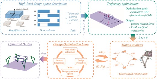
Overview of the computational design framework. With the prerequisite of the hyper-parameter of the design optimization problem, our framework first generates a sequence of trajectories with the minimized accumulative ground reaction force. Then, via the inverse kinematics and leg Jacobian provided by the motion analysis process, our design optimization loop iterate and evaluate the robotic limb design candidates, resulting in the final optimal design.
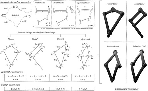
We unify the existing practical robot limb design as a generalized four-bar mechanism, leading to a large linkage-based robotic limb design pool for comparing various leg configurations. The kinematic constraints and design parameters for specific designs are listed. The engineering prototypes are fabricated by 3D printing using nylon material, sharing the same three-motor actuation module used in the hardware experiments later.
In the rest of this study, Section 2 presents the generalization of linkage-based robotic limbs and optimization problem formulation based on an energy-efficiency metric. Validation with hardware experiment and further discussion are enclosed in Section 3. Section 4 presents the conclusion, limitations, and future work, which concludes this study.
2. Method
2.1 Parametric design generalization of robotic limbs
We propose a parametric design generalization method for robotic limbs by reconfiguring the kinematic constraints, as shown in Fig. 3. We structurally formulate any robotic limb as a generalized four-bar linkage defined by the design parameters, including link lengths a, b, c, d and twist angles α, β, γ, δ following the standard Denavit–Hartenberg convention (Denavit & Hartenberg, 1955). For rotary joints, we set up all offsets as zeros and all revolute variables for motion generation. One can set the offsets as control variables and revolute variables as design parameters for prismatic joints. We also introduce a spherical radius r as a design parameter. Links with non-zero lengths are mathematically equivalent to a spherical link with an infinite radius r. When spherical radius r is a fixed value, we can produce a spherical link with intersecting joint axes. As a result, we achieved three link designs by changing the relationship among these design parameters, including the planar link, twisted link, and spherical link.
The planar link is the simplest case where the joint axes are parallel (α = 0, a ≠ 0, and r = ∞). Theoretically speaking, the offset values are usually set as zeros. Engineers usually introduce offsets in a cycle of positive and negative values in adjacent links to avoid physical collisions. This also applies to the design of twisted and spherical links.
The twisted link is similar to the planar one except for a non-zero twist angle (α ≠ 0, a ≠ 0, and r = ∞), resulting in a pair of non-parallel joint axes. In this study, they are used for the overconstrained linkages, and a Bennett ratio between the link length and the sine of twist angles may be further introduced as a constraint.
The spherical link is a special case with intersecting joint axis and non-zero arc length (α ≠ 0 and a ≠ 0). The spherical radius r is now a fixed value C and designed as a link on a spherical workspace (Lum et al., 2004). This is a common design approach called the alternative form, which is very flexible based on the need for expression or engineering convenience.
2.1.1 Linkage-based limb configurations
Next, we summarize four linkage-based design specifications based on the generalized robotic limb: planar, serial, Bennett, and spherical limbs. All designs presented here leverage a coaxially arranged dual-actuator design to enable leg motion through a linkage transmission (or its variants). Some can directly achieve 3D motion using two actuators, such as the Bennett Limb and the Spherical Limb, while others must add a third motor on the hip joint to enable 3D spatial motion.
The Planar Limb is when only planar links are used, as shown in the kinematic illustration and practical rendering. In this case, all twist angles are zero for the four links. Although one can choose different lengths for the four links, a common practice is to make the two links closer to the body equal and smaller than the other two equal links closer to the ground. For example, the Minitaur by Ghost Robotics (Kenneally et al., 2016) and the Stanford Doggo (Kau et al., 2019) are prototypes adopting such a design configuration. The symmetrical parallel configuration enables a lightweight design and a wide range of motion actuated by only two motors. However, it is limited in 3D motion due to the lack of a hip joint, making it challenging to turn on the spot.
The Serial Limb presented here is probably the most widely adopted design configuration for many modern quadrupeds. It is kinematically equivalent to a serial two-bar open chain but designed as a closed-loop four-bar planar linkage with an extended foot or lower limb. Within the four-bar loop, the opposite links are designed with equal lengths but adjacent links are designed with a large ratio in length to achieve agile locomotion and compact design. Examples such as the Cheetah robot by MIT (Seok et al., 2013), Panther by KAIST (Ding et al., 2021), and A1 by Unitree (Unitree Robotics, 2023) all adopted this leg configuration.
The Bennett Limb is a new design reported recently (Feng et al., 2021) that uses the twisted links sharing the same Bennett Ratio (a/sin α = b/sin β) to form a Bennett linkage as a robotic limb. This design leverages the spatial motion of twisted links to enable movement in 3D space actuated by two motors in each limb (Gu et al., 2022). Alternatively, one can add a hip actuator to further expand its manipulability in a robotic limb, which will be demonstrated later in this study.
The Spherical Limb is also a new design that has been well-researched regarding its kinematics but reported here as a robotic limb for the first time in literature (to the best of our knowledge). It applies the same working principle in design but uses the spherical link as the basic unit of the linkage. Similar to the Bennett limb, it can achieve spatial motion using only two actuators but is compatible in design to add a third motor to the hip joint.
2.1.2 Design reconfiguration of robotic limbs
The workflow summarized in Fig. 3 describes our proposal for parametrically generalizing robotic limb designs. We assume all designs share the same three-actuator configuration with a hip joint mounted to the body frame, intersected with two actuators in a coaxial arrangement, connected with two links of a four-bar linkage either in a planar, serial, Bennett, or spherical configuration. The following shows how one can reconfigure these design parameters to obtain different limb designs. Note that one can start from any of these designs to get the others, making the proposed method a robust pipeline for parametric design generalization of robotic limbs.
Start with the Bennett Limb configuration as the initial design, where sin α/a = sin β/b, and r = ∞.
Next, we can obtain a Spherical Limb by setting all link lengths to zero to relax the Bennett Ratio constraint. After doing so, we can set different values for the arc lengths (or twist angles) and introduce r = C to obtain a closed loop on a sphere.
Alternatively, we can obtain a Planar Limb by changing the twist angles to zero to relax the Bennett Ratio constraint. After doing so, we can set different values for the link length as long as we can obtain a closed-loop linkage.
Finally, we can obtain a Serial Limb by assigning different sets of length values for the link and extending the Planar Limb’s tip length to Ls .
2.1.3 Kinematics of the generalized robotic limbs
The kinematic analysis involves mapping configuration space to joint space and the Jacobian between the linear and angular velocities in the corresponding workspace. We assume that all limb configurations feature a lightweight design with negligible inertia. It is equivalent to modeling the limbs as an open serial chain with all motors closer to the body center. Among the three motors, one actuates the hip, and the other two are placed coaxially, independently actuating the thigh and knee joints. As a result, we can use the same actuator layout to accommodate four sets of representative limb configurations for a generalized kinematic analysis for parametric limb design optimization.
We formulate the forward kinematics of the generalized robotic limb using the product of the exponential formula (Lynch & Park, 2017) as
where |$\mathcal {S}_k \in \mathbb {R}^{6}$| is the initial velocity screw of joint k (k = 1, 2, 3), θk is the corresponding joint angle, and P0 ∈ SE(3) is the initial position of the foot tip. The detailed derivation of the forward kinematics is enclosed in Appendix A. Similarly, the inverse kinematics (IK) of the involved robotic limbs can be resolved analytically. And the detailed derivation of the IK is enclosed in Appendix B.
The space Jacobian Js (θ) relates the joint angular velocity vector |$\dot{\theta }$| to the foot’s screw velocity |$\mathcal {V} \in \mathbb {R}^{6}$|. Using qi to represent the actuator rotation for each joint, the leg Jacobian |$J(q) \in \mathbb {R}^{6 \times 3}$| can be derived by multiplying Js (θ) and derivative of joint angle for actuator angle. Therefore, the velocity screws |$\mathcal {V}$| of the foot can also be obtained as the following:
where |$J_{\mathcal {S}_k}=Ad_{e^{[\mathcal {S}_1]\theta _1}\cdots e^{[\mathcal {S}_{k-1}]\theta _{k-1}}}(\mathcal {S}_k)$|. Note that the robotic limbs’ actuator torque can be estimated using the leg Jacobian τ = J(q)Tf, where f refers to the ground reaction force.
2.2 Formulating the optimization problem
As shown in Fig. 2, the proposed computational framework involves three stages. Firstly, users define the basic parameters of robots and tasks. Then, according to the given setting, our trajectory optimization algorithm generates a sequence of ground-reaction forces with minimized motion energy trajectories. Finally, we optimize the leg configuration and design parameters to solve for a design with the highest energy efficiency. For versatility, the framework aims at guiding the user to find a proper set of robotic limb design parameters in the early stage while also suggesting the detailed parameters of the limb with analytical justification.
We implemented the optimization with the following assumptions. First, we assume that the locomotion tasks can be described by the robot’s center of mass and feet and are independent of the leg configuration and design parameters. Next, we consider that the optimal trajectories would result in proper limb design space for given tasks. Moreover, we restrict our attention to analysing the disparate leg configuration and parameters rather than other morphological features such as extra compliant elements or flexible spines. Finally, we leverage the kinematic generalization of the link mechanism to make the trade-off between disparate limb configurations. In the following sections, we address the optimization problem to solve for a limb configuration and design parameters of a quadruped robot against its energy efficiency for simple tasks such as forward, lateral, and turning on the spot.
2.2.1 Trajectory optimization formulation
Figure 4 shows the complete trajectory optimization formulation. The algorithm allows the users to transfer the basic robot parameters, desired tasks, and preferred gait patterns into the proposed trajectory optimization problem. Here, the users should provide the whole robot design parameters, including the mass of robot m and Cartesian inertia tensor I, as well as the nominal center of foot tips (end-effectors) and their boundary size. These parameters, defined before trajectory optimization, are not actively updated in the other robotic limb design optimization loop. On the other hand, the initial state r0, desired state rg, gait pattern, time duration T, time interval ΔT, the number of steps ns , and other task-related information should also be provided for the specified tasks.
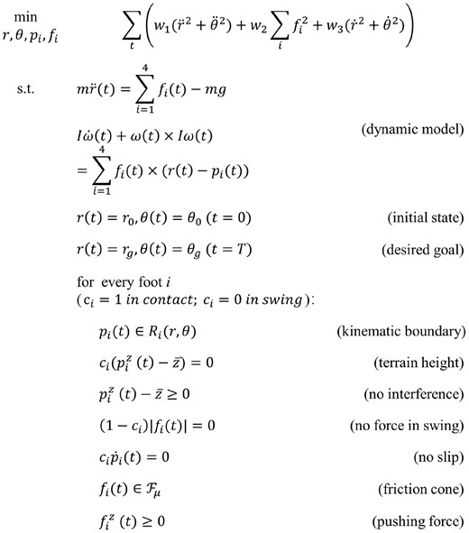
Formulation of the trajectory optimization problem.
As a result, we use the single rigid body dynamic model (SRBDM) to describe the dynamic characteristics of the simplified robot model (Winkler et al., 2018). Note that the dynamic effects caused by the legs during locomotion tasks are ignored during the optimization based on the assumptions above.
The above dynamic model relates the translational Center of Mass (CoM) acceleration |$\ddot{p}_{c} \in \mathbb {R}^{3}$| and body angular acceleration |$\dot{\omega }_c\in \mathbb {R}^{3\times 3}$| to the ground reaction force of each foot |$F_{i}\in \mathbb {R}^{3},i=\left\lbrace 1,2,3,4 \right\rbrace$|. Here, m is the total mass, g is the gravity vector, |$I_c\in \mathbb {R}^{3\times 3}$| is the centroidal rotational inertia of the body, and |$p_{i}\in \mathbb {R}^{3}$| is the position of the feet. For this stage, we model the robotic limbs as the distal contact points which relate the CoM of the robot and the environment, describing the contact behaviors. Besides the dynamic relationship, the kinematic characteristic between the foot position and mass center of the robot can be defined as
where Ri ∈ SO(3) is the matrix from the world to the body frame. We approximate the workspace of the foot by an ellipsoid of radii length a, b, c, centered at the foot’s nominal position. Additionally, other constraints such as the terrain height and friction cone are enforced for each foot contact point during motion. Note that the limb configuration and parameter would not be considered in the trajectory optimization stage since they are represented by the contact points with physical constraints, achieving high versatility of disparate design.
Therefore, at each discrete frame, the instantaneous state of robot st = [rt , θt, pt, i, Ft, i] can be represented by the CoM position |$r_{t}\in \mathbb {R}^{3}$|, orientation |$\theta _{t}\in \mathbb {R}^{3}$|, each foot’s contact position pt, i and contact force Ft, i, where i refers to the leg index. For a given task duration time T and time interval ΔT, the locomotion trajectory |$\mathcal {A}=[s_{0}, ..., s_{T}]$| is a sequence of discrete data that aggregates the state of the simplified robot at every single frame. The contact point states are parameterized for continuity and to reduce the number of variables. Here, we use multiple fifth-order polynomials to represent the stance force and set zero force for the swing phase. For each foot’s motion, we utilize multiple compound cycloids (Wu et al., 2009) to represent per swing phase and a constant value for the stance phase. Hence, the variables of the trajectory optimization problem are the states of mass center and parameterized foot motion and force |$\mathcal {X}_{T}=[r, \theta , p(t), F(t)]$|. The objective function is defined as the sum of weighted cumulative contact force, acceleration, and velocity, towards minimizing the energy cost of locomotion task in the trajectory planning stage, which is given by
where w1, w2, and w3 are set as 0.01, 0.0001, and 1 for practical experiments, respectively. Therefore, we transcribe the trajectory generation problem into the following optimization problem with finite decision variables and non-linear constraints, which is solvable by non-linear programming problem solvers.
2.2.2 Design optimization of robotic limbs
The next step is to find the optimal leg configuration and design parameters from the generalized limbs towards energy-efficient optimization, as shown in Fig. 2. The first step is to transfer the foot’s contact position pi from the world coordinate to the corresponding leg coordinate. Then, once the leg configuration is given, we can analytically calculate the IK of the limbs, mapping the end-effectors’ position |$p\in \mathbb {R}^{3}$| to actuators’ angle |$q\in \mathbb {R}^{3}$|, and the detailed analytical inverse solution of generalized robotic limbs can be referred in Appendix B. Note that the numerical method can also resolve the IK problem relatively with more computing time. And the next step is to calculate the required actuators’ torque, which is related to the contact force of feet. Since we adopt the robotic limb with light-weighted 3D-printed parts and the proximal actuator arrangement, the dynamic effects are negligible for both swing and stance in this study. It is a reasonable assumption when the limbs are light enough, and the generated motion is slow. The torque caused by the acceleration-related parts is minor to the torque associated with the contact force |$\mathcal {F}_{i} \in \mathbb {R}^{6 \times 1}$|. Therefore, the joint torque is determined by
where |$J(q)\in \mathbb {R}^{6 \times 3}$| is the Jacobian matrix of the respective limb. This simplification is also beneficial for ignoring the small weight variation of robotic limbs during the optimization process. The above assumptions would break down for quadruped robots with high dynamic motion and heavy limbs. However, these kinds of robots are also poorly described by the SRBDM and thus out of the scope of this study.
After the motion analysis stage, the next step is to evaluate and update the limb configuration and design parameters. Since the formulated problem is non-linear and non-smooth, CMA-ES, a numerical and derivative-free method, is leveraged to optimize the limb design (Hansen et al., 2003). A set of initial candidate designs are created, followed by evaluating their performance via an objective function which we try to minimize. Then, the design parameters of individuals are updated by repeating the interplay of variation and selection toward seeking the design parameters with minimum cost (Golberg, 1989). Various optimization metrics can be utilized here, for example, the COT, which is one of the most widely used metrics for comparing locomotion efficiency among quadruped robots and is defined as the average input power required to transport a robot with mass m at constant linear velocity v and earth gravity g (Seok et al., 2013). Some other widely-used metrics include the cumulative joint torque, mechanical energy, and mechanical COT (Chadwick et al., 2020). Here we consider proposing the mechanical energy efficiency (MEE) metric to satisfy the trade-off between the discrepancy and similarity of multiple tasks,
MEE is the minimum task energy ET ratio to the mechanical energy consumption EM. Since we leverage the single rigid body model to describe the dynamic characteristics of the robot, the minimum energy consumption ET during each task can be obtained by the integral of the energy change of the main body,
where |$f_{i}\in \mathbb {R}^3,i=\left\lbrace 1,...,4 \right\rbrace$| is the contact force of each foot. |$\dot{r}\in \mathbb {R}^3$|, |$\dot{\theta }\in \mathbb {R}^3$| and |$\tau \in \mathbb {R}^3$| are the linear velocity, angular velocity, and torque of body, respectively. The minimum task energy consumption ET represents the lowest required energy for the simplified robot to implement a specific task. Note that the minimum task energy consumption ET is only related to the task itself and does not change with the design iteration of robotic legs. Furthermore, once the trajectory optimization of the task is finished, its ET would also become a constant value. On the other hand, mechanical energy consumption is defined as the cumulative mechanical energy of all the actuators as follows:
in which |$\tau _{n}\in \mathbb {R},n=\left\lbrace 1,...,12 \right\rbrace$| is the actuator torque and ωn is the corresponding angular velocity. The mechanical energy consumption EM is closely related to robotic limb design and tasks. Regarding a task-specific optimization problem, the robotic limb design with the lower mechanical energy consumption EM is preferred. Hence, as a dimensionless scaled index, MEE metric η can be utilized to equivalently compare the performance of robotic limb design under different tasks. The user-defined optimization goal is the linear combination of weighted task-specific energy efficiency metrics, leading to the robotic limb design with the most comprehensive energy-efficient performance under the given basic tasks as targets,
3. Results and discussion
We conducted three sets of experiments, including (i) the hardware test for direct comparison of the generalized limbs against energy efficiency and robotic limb design optimization against gait trajectory generation for (ii) a single task and (iii) multiple tasks, followed by a discussion of the corresponding result. Please find a video demonstration of the results in Appendix C.
3.1 Hardware verification for generalized limb design
We tested the proposed framework to optimize the robotic limb design of a prototype quadruped hardware. The detailed parameters of quadruped and the additional settings are listed in Table 2. We specified forward locomotion, lateral locomotion, and turning on the spot as the target tasks in the optimization stage. In the trajectory optimization stage, the number of discrete frames is set to 80, with a time interval from 0.033 to 0.05 s for tasks under different velocities. The optimized trajectories were obtained by Interior Point Method solver with a python wrapper (Ipopt; Wächter & Biegler, 2006). We set the maximum number of iterations for the solver to 2000, and the average solving time is about 2.5 h. In the robotic limb optimization stage, we implement the open-source library PYCMA (Hansen et al., 2019) and speed up the calculation by providing the analytical IK solution of the candidate leg configuration. The most time-consuming step is evaluating each individual with an average of 0.4 s. The population size and the number of generations should be greater than 20 and 100 to obtain consistent results, and the average computation time is about 40 min. The results were computed using Intel Core i5-11400F 2.9GHz CPU.
The parameter setup for the trajectory optimization stage and the penalty terms for the design optimization stage. Note that the avoidance of collision and IK accuracy are imposed during the stage of limb design optimization but without a specific boundary value.
| Trajectory optimization stage | |||
|---|---|---|---|
| Duration time: 2.67 s/3.2 s/4.0 s | Number of frame: 80 | Body height: 0.138 m | |
| Number of step: 4 | Task type: forward/lateral/turning | Friction coefficient: 0.9 | |
| Robot mass: 2.2 kg | Boundary size: [0.06 m, 0.04 m, 0.03 m] | Max iteration number: 2000 | |
| Gait type: Trotting/bounding | Foot position: [0.137 m, 0.138 m, −0.138 m] | Gravity vector: [0,0,−9.81m s−2] | |
| Robotic limb design optimization stage | |||
| Soft constraints | Value | Soft constraints | Value |
| Actuator limit output torque | 3.0 Nm | Total leg length | 0.2 m |
| Actuator limit angular velocity | 50 rad s−1 | Avoid leg collisions | No collision |
| Limit allowable angle | 3.14 rad | Tracking error | IK accuracy verification |
We validate our algorithm via a small quadruped hardware with replaceable 3D-printed robotic legs, as shown in Fig. 5. The robot adopted the design of arranging actuators near CoM, achieved by coaxial output flange design, towards being consistent with the SRBDM. The leg links are fabricated by PA-12 (or Nylon 12) for their mechanical strength and high tenacity, and the leg tip is coated by silicone hemisphere (Dragon skin 10). Each leg has three Dynamixel XM-430 W-210-R servos with 3.0-Nm stall torque at 12.0 V. An external computer is connected to the robot to replay the planned motion without involving any additional balance controller. And the power of the robot is also supplied by an external stabilized voltage source.
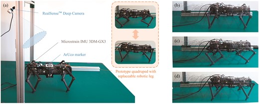
(a) Hardware verification setup. (b) Overlaid snapshots of a quadruped with Bennett robotic limb for forward locomotion task. (c) Overlaid snapshots of a quadruped with a nominal planar robotic limb. (d) Overlaid snapshots of a quadruped with an optimized planar robotic limb.
Three robotic legs with different configurations and parameters are involved, including the Bennett type, planar type before optimization, and optimized planar type. All robotic legs share the same cross-section and total length. During the experiment, we used an Intel RealSense camera to record the displacement of the robot by the attached ArUco marker (Garrido-Jurado et al., 2014), as well as tracking its pose via an inertial measurement unit. Additionally, the tethered computer could receive and record the servos’ position and current feedback.
For validation, we replay the same forward locomotion trajectory, which is generated and optimized by the algorithm in the Section. 2.2, via the above three types of robotic legs. Equation (9) can obtain the theoretical mechanical energy power for different leg configurations. Regarding the hardware experiment, since the actuators do not have torque senor, the measured mechanical energy power is calculated by multiplying the actual input electric power by the efficiency factor. Figure 6 presents the mechanical energy cost and actuator current for various leg configurations to replay the same trajectory. Both of these three types of legs were ranked by the theoretical and measured results, which have similar trends and order in ranking. After normalization, the theoretical cost matched the measured one with a relatively small averaged mean-square error of 0.0042, indicating the effectiveness of the proposed method in the application.
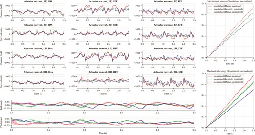
Hardware experiment results by comparing the measured data against the simulated result for nominal and optimized designs, which show the same trend.
3.2 Computational limb design for a single task
After verifying our design framework in the hardware prototype, we apply the optimization to the platform with the same initial setup parameters (see Table 2) for comparing the performance of specific leg configurations under disparate basic locomotion tasks, respectively. Here, we still choose MEE as the performance metric for all the tasks, towards diminishing the diversities of tasks and achieving practical comparison among diverse leg configurations. In the task selection level, we focused on the omni-directional locomotion ability of quadruped robots. Hence, three basic sub-tasks were separated, including forward locomotion, lateral locomotion, and turning on the spot. In the limb optimization level, we took the link length and the particular parameters of corresponding leg configuration (twist angle for Bennett robotic legs and link radius for spherical ones) as the optimization variables. Meanwhile, the total leg length, the cross-section of the link, and the material were imposed constraints to maintain a similar total mass and centroidal inertia tensor and reinforce the SRBDM assumption. The leg layout was set to a mammal with a symmetrical arrangement. Additional robotic limb optimization setup parameters and soft constraints were listed in Table 2, including physical and hardware-level constraints, ensuring the final design’s physical feasibility.
We generated the three kinds of basic tasks’ trajectories under the same initial robotic setup parameters with the only differences in motion velocity. Then, we optimized the diverse leg configurations in the four-bar family (Bennett robotic leg, planar one, serial one, and spherical one) for each task, respectively, towards searching the best performance each leg configuration can achieve for the given basic tasks and design setup parameters (see Table 3). As illustrated in the table, when only the forward locomotion task was involved as the optimization target, the planar linkage-based robotic legs have the best performance in energy efficiency (83|$\%$| in average), followed by the spherical ones (78|$\%$|), Bennett ones (70|$\%$|), and serial ones (60|$\%$|), successively. However, when optimizing the performance in lateral locomotion tasks, the Bennett robotic leg configuration demonstrates a relatively significant superiority in the MEE metric, about 87|$\%$|, reflecting the potential advantages of Bennett robotic legs in lateral locomotion. On the other hand, only 55|$\%$|–65|$\%$| energy efficiency radio can the planar robotic leg achieve in this kind of task, similar to the serial and spherical ones. Finally, for the turning-on-spot tasks, the spatial Bennett robotic legs still have outstanding MEE metric values (85|$\%$| on average), followed by the planar ones. And the spherical robotic legs still have relatively inferior performance in these tasks.
Robotic limb optimization results for the basic tasks under different speeds.
| Energy efficiency under different leg configuration (after optimization) | |||||
|---|---|---|---|---|---|
| Task type | Task energy cost [J] E | Bennett leg [%] EB | Planar leg [%] EP | Serial leg [%] ES | Spherical leg [%] ESp |
| Forward (dis = 0.4 m) | |||||
| 0.100 m s−1 | 8.08 | 75.75 | 94.06 | 67.10 | 84.35 |
| 0.125 m s−1 | 6.90 | 78.56 | 89.32 | 61.82 | 84.63 |
| 0.150 m s−1 | 6.31 | 55.82 | 67.20 | 52.17 | 64.77 |
| Lateral (dis = 0.4 m) | |||||
| 0.100 m s−1 | 8.92 | 93.30 | 65.24 | 58.38 | 53.68 |
| 0.125 m s−1 | 7.43 | 78.10 | 54.03 | 53.32 | 47.97 |
| 0.150 m s−1 | 7.83 | 89.68 | 67.40 | 67.49 | 60.20 |
| Turning (ang = 2 rad) | |||||
| 0.500 rad s−1 | 8.28 | 90.85 | 75.97 | 65.67 | 62.71 |
| 0.625 rad s−1 | 7.35 | 92.06 | 69.39 | 62.28 | 60.13 |
| 0.750 rad s−1 | 6.39 | 76.96 | 60.42 | 56.67 | 54.18 |
Several key findings of the optimization results are followed. First, optimizing link length and parameters results in a significant torque reduction rather than decreasing the joint angular velocity. This is also consistent with the trend observed in the hardware experiments, in which the actuators’ peak current notably decreased. Although less significant, the energy-efficient design prefers reducing the length of the thigh link and increasing the length of the shank link towards reducing the moment arm of the joint, which is also observed by (Ha et al., 2018b; Chadwick et al., 2020). Secondly, we found that when it comes to optimizing lateral locomotion, the limb design prefers the symmetrical thigh with a relatively longer length, even though there are no constraints on the symmetry of a single leg (see Fig. 7). An interesting phenomenon for the spherical limbs is that the optimized design trend selects the link with the maximum radius, which may perform similarly to the planar ones.
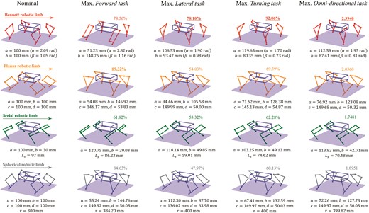
Nominal and optimized design for hardware platforms. Top to bottom row: Bennett linkage robotic limb (red); planar linkage robotic limb (orange); serial robotic limb (green); spherical linkage robotic limb (grey).
These examples demonstrate that a remarkable enhancement in the MEE metric for a given task is possible by optimizing the leg configuration, link length, and other parameters but may have detrimental effects on different tasks. Compared with optimizing link parameters, sorting the appropriate leg configuration might be much more productive in promoting the performance of quadruped design. Furthermore, any leg configurations might have potential benefits for specific tasks. Therefore, in the general case, the designer should pursue the design parameters with the most comprehensive performance for all tasks involved.
3.3 Computational limb design for multiple tasks
In addition to optimizing and comparing leg configuration on every task, we apply the proposed framework to the current robotic platform to optimize the limb design under multiple target tasks. The optimization metric is the linear combination of weighted task-specific energy efficiency ratio, indicating a comprehensive evaluation of the involved tasks. Note that the task weight factor selection would have a crucial influence on the final optimization result. In the general case, this user-defined parameter is determined by the possible working scenarios and the frequency of each task. This study focuses on the all-around performance of all the basic sub-tasks towards energy-efficient omni-directional locomotion capability on flat ground. Therefore, we select all three types of basic sub-tasks (forward locomotion, lateral locomotion, and turning on the spot) as the optimization goal and give the same weight factor w = [1, 1, 1].
Table 4 summarizes the optimized parameters and metric value. We can find that the Bennett robotic limb has the most outstanding energy efficiency performance among these leg mechanisms for given robot basic design parameters and task weight, which is also consistent with the results shown in Section 3.2 to a certain degree. Except for the planar robotic limb, the other two kinds of design show an apparent disparity compared with the Bennett one, which is about 20|$\%$| descent. In contrast, optimizing the link parameters for a given leg configuration has a relatively mirrored improvement of the performance metric (nearly 4|$\%$|–15|$\%$|). Note that the above results are also related to the selection of initial design parameters. More specifically, if the optimization starts with a given initial design close to the optimal result, the convergence speed would increase, and the improvement ratio might not be significant. Meanwhile, the designer can also concurrently implement multiple optimizations with the randomly sampled initial designs for optimality.
Robotic limb optimization results for multiple tasks with equivalent weight. The value of optimization metric G is the linear combination of three basic tasks with the same task weight. And the ΔG represent the change rate of the final result concerning the nominal Bennett design (the value in the brackets represents the increasing rate compared with the design before optimization).
| Design parameter | Optimization metric | ||||||
|---|---|---|---|---|---|---|---|
| Link length [mm] (twist angle [deg] or radius [mm]) | Tip length [mm] | Multi-primitive EE | |||||
| w = [ 1, 1, 1 ] | a(α) | b(β) | c(γ) | d(δ) | Ls | G | |$\Delta G{[}\%{]}$| |
| Bennett | |||||||
| Nominal | 100.00 (135.00) | 100.00 (45.00) | 100.00 (135.00) | 100.00 (45.00) | – | 2.3065 | - (−) |
| Max. MEE | 112.59 (111.67) | 87.41 (46.18) | 112.59 (120.52) | 87.41 (46.18) | – | 2.3940 | +3.79 (+3.79) |
| Planar | |||||||
| Nominal | 100.00 (−) | 100.00 (−) | 100.00 (−) | 100.00 (−) | – | 1.7450 | −24.34 (−) |
| Max. MEE | 76.92 (−) | 123.08 (−) | 149.68 (−) | 50.32 (−) | – | 2.0360 | −11.73 (+16.68) |
| Serial | |||||||
| Nominal | 100.00 (−) | 30.00 (−) | 100.00 (−) | 30.00 (−) | 97.00 | 1.6835 | −27.01 (−) |
| Max. MEE | 113.82 (−) | 42.71 (−) | 113.82 (−) | 42.71 (−) | 70.48 | 1.7481 | −24.21 (+3.84) |
| Spherical | |||||||
| Nominal | 100.00 (300.00) | 100.00 (300.00) | 100.00 (300.00) | 100.00 (300.00) | – | 1.6847 | −26.96 (−) |
| Max. MEE | 72.26 (399.82) | 127.73 (399.82) | 149.97 (399.82) | 50.03 (399.82) | – | 1.8951 | −17.84 (+12.49) |
According to the above optimization results of the robotic limbs for multiple tasks, several key findings are listed. First, a possible significant improvement of the performance metric can be achieved by employing the proper leg mechanism or configuration rather than optimizing the continuous link parameters for a specific limb design. In other words, although no unique winning leg configuration is optimal for all tasks, identifying the appropriate leg mechanism is crucial. Achieving the optimal trade-off among possibly contradicting task requirements might lead to a comprehensive and practical design between one extreme design and the other one. Finally, the spatial overconstrained robotic limb (Bennett linkage in this study) may have the possible advantage in improving the all-around performance, specifically, the energy efficiency of omni-directional locomotion. While above findings also have some limitations. Specifically, they are closely related to the basic robot parameters and user-defined task weights. When these hyper-parameters are changed, the resulting design might differ from the above ones. Therefore, finding the relevance between the high-level layout of robots and the preferred leg mechanism is a potential research question to be addressed in future work.
3.4 Towards versatile and energy-efficient motion
Versatility is one of the main driving factors for adopting robots in engineering applications. To ensure a versatile design, our computational design framework considers the potential scenarios with the combination of the tasks that the robot could face and optimizes the configuration and design parameters based on the weighted energy-efficient metric. When quantifying the versatility of robots, a practical attempt could be found in (Nie et al., 2013), in which the researchers also quantitatively propose reasonable sub-task weight coefficients for multiple domains. Compared with the omni-directional performance highlighted in this study, the existing quadruped robot mainly moves forward and changes orientation with little lateral movement. Therefore, as illustrated in Table 5, we reproduced the robotic limb optimization experiment with different task weight coefficients. The first set of weight coefficients (wA ) represents the equivalent proportion of all the tasks and the second one (wB) is defined by the above literature for practical flat terrain locomotion, followed by three task-specific weight settings (wC, wD, wE). The energy efficiency of sub-tasks and the overall optimization metric value are presented for each coefficient set.
Robotic limb optimization results for different task weights.
| Task weight | Bennett limb | Planar limb | Serial limb | Spherical limb | ||||||||||||
|---|---|---|---|---|---|---|---|---|---|---|---|---|---|---|---|---|
| F [%] | L [%] | T [%] | G | F [%] | L [%] | T [%] | G | F [%] | L [%] | T [%] | G | F [%] | L [%] | T [%] | G | |
| wA | 71.5 | 77.1 | 90.6 | 0.79 | 83.0 | 51.7 | 68.8 | 0.67 | 61.2 | 53.0 | 60.5 | 0.57 | 82.0 | 47.3 | 60.0 | 0.62 |
| wB | 71.8 | 76.7 | 90.5 | 0.80 | 83.2 | 52.9 | 69.6 | 0.72 | 60.9 | 52.8 | 61.0 | 0.59 | 82.1 | 47.3 | 60.0 | 0.66 |
| wC | 78.5 | Fail | Fail | 0.78 | 89.7 | 34.5 | 47.4 | 0.89 | 61.8 | 53.2 | 57.7 | 0.61 | 84.6 | Fail | Fail | 0.84 |
| wD | 69.5 | 78.1 | 88.8 | 0.78 | 79.3 | 54.0 | 66.5 | 0.54 | 61.7 | 53.3 | 58.9 | 0.53 | 71.9 | 47.8 | 58.2 | 0.47 |
| wE | 67.4 | 74.1 | 92.1 | 0.92 | 83.0 | 52.8 | 69.6 | 0.69 | 58.5 | 50.3 | 62.2 | 0.62 | 82.8 | 45.3 | 60.1 | 0.60 |
Note: F: Forward locomotion task; L: Lateral locomotion task; T: Turning task; G: Optimization metric. The overall optimization objective is the optimization metric G. For each task weight setting, we present the optimal objective value and the energy efficiency of every sub-tasks. wA = [0.33,0.33,0.33], represents the omni-directional performance; wB = [0.41,0.18,0.41], introduced in literature (Nie et al., 2013); wC = [1,0,0], wD = [0,1,0], and wE = [0,0,1], are sub-task specialization weights.
We can find that when the weight coefficients of sub-tasks are modified, the energy efficiency will result in relevant changes. More specifically, when the proportion of a given task increased, the corresponding energy efficiency would also be improved, which is obviously in the sub-task-specific experiments. Although less significant, compared with the balanced task weight (wA), the practical one (wB) results in a higher objective score (G), respectively. And although the Bennett robotic limbs still have the most outstanding overall score (0.8) over the alternative task weight setting (wB), the gap with the planar one has been significantly reduced. Similarly, other robotic limbs, which have relatively poor performance at the lateral locomotion task, also have a higher increase rate than the Bennett one. Additionally, it is remarkable that the optimal design for a specific sub-task might be infeasible for other tasks. This phenomenon is more like to appear in the spatial robotic limb design, such as the Bennett and spherical case, due to the reduced workspace volume caused by the special geometric constraints. Therefore, one should pay attention to the parameter selection of the spatial robotic limb design to adapt to all the potential tasks. One of the possible solutions is to leverage the proposed computational design framework in this study to guide and forecast the design process.
On the other hand, one of the aims of this study is to understand what mechanical design characteristics allow the robot systems to obtain a high level of energy efficiency and versatility without increasing the complexity. Manipulability is one of the performance metrics widely adopted in robotics, which is defined as
where λi is the eigenvalue of matrix A = JJT and J is the analytical Jacobian matrix of the robotic limb. The geometric representation of the manipulability is proportional to the volume of the speed ellipsoid, indicating the capability of the robot’s end-effector to perform velocities and acceleration or to exert force on the environment in a given posture. As illustrated in Fig. 8, we present the workspace of the optimized robotic limb concerning the colored manipulability metric. Note that the upper boundary of each limb is different to represent the feature of the distribution of manipulability. We can find that the Bennett robotic limb has the maximum manipulability metric (4.357 × 10⁻³), as well as the maximum cumulative manipulability concerning the given locomotion trajectories, indicating the possible association between the manipulability and energy efficiency to a certain degree. Although less significant, when we optimize the design parameters based on the energy efficiency metric, the manipulability also has an increasing trend, consistent with Kim et al. (2010). Therefore, manipulability analysis can enhance the energy efficiency of the quadruped robot to a certain degree. Last, we recognize that control and sensing techniques may influence a robot system’s mobility performance, while these items are out of the scope of this study and will be addressed in the future.
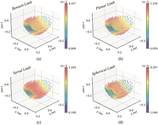
Manipulability metric in an optimized robotic limb. (a) Bennett robotic limb; (b) planar robotic limb; (c) serial robotic limb; (d) spherical robotic limb.
4. Conclusions
In this study, we propose the computational design framework for robotic limb optimization towards minimizing the energy cost during omni-directional locomotion for quadruped robots with a linkage mechanism. Via the generalization of the leg mechanism, we can optimize both the discrete leg configuration and continuous link parameters of quadruped robots within the assumptions of a single rigid body dynamics model. We can optimize the limb design based on user-defined hyper-parameters and weighted primitive tasks while undertaking the physical feasibility of the final design, subject to imposed hardware limitations. For validation, we implement the hardware experiments on forward trotting locomotion tasks with diverse limb designs. The measured data from the prototype robot shows the same trend as the forecasted one with a relatively small normalized mean square error. Optimizing the leg configuration for primitive tasks indicates that it is possible to improve the energy efficiency by approximately 10|$\%$|–20|$\%$|. On the other hand, the optimization result on multiple primitive tasks indicates the potential advantage of overconstrained robotic limb design in promoting energy efficiency for omni-directional locomotion. In the early phase of novel quadruped robot design, our framework can help the designers to generate feasible and optimized limb designs for specific task requirements or provide instructive insights in determining the design parameters, such as leg configuration and link parameters.
In this study, our algorithm only considers omni-directional locomotion on flat terrain. At the same time, some tasks that require more complex interactions with the environment, such as climbing slopes and stairs, are also valued by the designers. One possible solution is introducing various terrain constraints in the trajectory optimization stage and further collision detection between limb linkages and the environment, which might increase the non-linearity of the optimization problem and computing time. However, it can still be handled by the proposed formulation and non-linear programming problem solver. Although only the robotic limbs in the four-bar family and its variants are addressed in this study, one can introduce almost any of the three DoF robotic limbs with explicit kinematic and dynamic derivation to the proposed computational framework, which might be explored in future work. Limited parameters are involved in optimization during the stage of trajectory optimization, which is aimed at enhancing the dominant role of the designer. Still, choosing these parameters, such as total mass and nominal stance position, may significantly influence the optimization preference and lead to a distinct final design. Therefore, one of the possible directions of future work is to include more design parameters and resolve the limb design problem as a co-optimization problem with a reinforcement learning approach (Kim et al., 2023).
Acknowledgement
This work was supported by the Ministry of Science and Technology of China under Grant 2022YFB4701200, National Science Foundation of China under Grant 62206119, and The Science, Technology, and Innovation Commission of Shenzhen Municipality under Grants JCYJ20220818100417038, ZDSYS20220527171403009 and SGDX20220530110804030.
Author contributions
Yuping Gu: Conceptualization, Methodology, Investigation, Visualization, Writing. Ziqian Wang: Investigation. Shihao Feng: Investigation. Haoran Sun: Investigation. Haibo Lu: Funding Acquisition. Jia Pan: Funding Acquisition, Project Administration, Supervision. Fang Wan: Funding Acquisition, Project Administration, Writing. Chaoyang Song: Conceptualization, Methodology, Visualization, Funding acquisition, Project administration, Supervision, Writing.
Conflict of interest statement
The authors declare that they have no competing interests.
References
Appendix A: Forward Kinematics
As mentioned in Section 2.1.3, a general forward kinematic can be described as the end-effector position and orientation concerning the base frame, which is a homogeneous transformation matrix,
where |$\mathcal {S}_k$| is the screw axes of each joint, respectively, and P0 is the initial position and orientation of the end-effector, which can be described as
and |$e^{[\mathcal {S}_k]\theta _k}$| is the twist exponent matrix, which the Rodrigues formula can compute.
The homogeneous transformation matrix can be described as follows in IK:
where P = [px , py , pz ] is the end-effector position in leg frame.
Appendix B: IK
In Planer configuration, for a given end-effector coordinate P = [px , py , pz ], the analytical solution of IK can be expressed as q = q(θi) = q(fi (P)), which is
where
Serial configuration can be considered a special case of Planer configuration. Therefore, the IK are in the same form.
For Bennett configuration, the IK can be resolved as
where
and the motor angle q can be represented as follows:
In Spherical configuration, the joint angle can be derived along spherical geometry. Therefore, the IK will be obtained,
where
Based on the geometrical condition, the motor angle q = [q1, q2, q3] can be resolved
where
The symbol ‘±’ implies multiple solutions in the solving process, and we will filter the appropriate solutions for the final result.
Appendix C: Supplementary video
A supplementary video demonstrating the robot prototype in simulations and experiments.
