


Abstract
The development of communicating modular cardiac rhythm management systems relies on effective intrabody communication between a subcutaneous implantable cardioverter-defibrillator (S-ICD) and a leadless pacemaker (LP), using conducted communication. Communication success is affected by the LP and S-ICD orientation. This study is designed to evaluate the orientation of the LP and S-ICD in canine subjects and measure success and threshold of intrabody communication. To gain more human insights, we will explore device orientation in LP and S-ICD patients.
Canine subjects implanted with a prototype S-ICD and LP (both Boston Scientific, MA, USA) with anterior–posterior fluoroscopy images were included in this analysis. For comparison, a retrospective analysis of human S-ICD and LP patients was performed. The angle of the long axis of the LP towards the vertical axis of 0°, and distance between the coil and LP were measured. Twenty-three canine subjects were analysed. Median angle of the LP was 29° and median distance of the S-ICD coil to LP was 0.8 cm. All canine subjects had successful communication. The median communicating threshold was 2.5 V. In the human retrospective analysis, 72 LP patients and 100 S-ICD patients were included. The mean angle of the LP was 56° and the median distance between the S-ICD coil and LP was 4.6 cm.
Despite the less favourable LP orientation in canine subjects, all communication attempts were successful. In the human subjects, we observed a greater and in theory more favourable LP angle towards the communication vector. These data suggests suitability of human anatomy for conductive intrabody communication.
What’s new?
Characteristics and conditions of intrabody conductive communication between a leadless pacemaker (LP) and a subcutaneous implantable cardioverter-defibrillator (S-ICD) are explained.
A communication vector is created by the transmitting and receiving electrode of the S-ICD and the LP is positioned in this communicating vector in order to recognize the transmitted signals by detecting a voltage difference between the anode and cathode of the LP.
Canine models have an unfavourable angle of the LP towards the communication vector to detect voltage differences, which decreases the probability of communication success. However, the small distance between the transmitting (S-ICD coil) and receiving (S-ICD can) electrodes in the canine model creates a dense communication field, which is favourable for intrabody communication success.
The human data shows more favourable angles of the LP compared with the canine model. However, the distance between the transmitting and receiving electrode of the S-ICD are positioned further apart, creating a less dense communicating vector.
Introduction
The introduction of leadless pacemakers (LP) and the subcutaneous implantable cardioverter-defibrillator (S-ICD) both omit the use of transvenous leads and are less invasive methods to provide cardiac pacing and defibrillation.1–3 Successful combined implants of both devices have been described in a few case reports.4,5 In these cases, the LP and the S-ICD coexist, but are not able to complement each other. The S-ICD is limited to terminating ventricular arrhythmias by shock therapy only. Communication with the LP provides the ability to deliver antitachycardia pacing (ATP) when ventricular arrhythmias are detected by the S-ICD. The development of communicating modular cardiac rhythm management (mCRM) systems, beyond even these described, will rely on safe and effective intrabody communication.
Unidirectional intrabody communication between a S-ICD and a LP (both Boston Scientific, MA, USA), using conductive communication, has been described using body tissue as a conductor.6,7 This type of intrabody communication is established by alternating current pulses sent from a transmitting electrode to a receiving electrode on the S-ICD and sensed by a dipole of electrodes on the LP, requiring a small amount of energy in animal models.8 Communication success can be affected by the distance of the S-ICD communicating electrodes, otherwise referred to as the communication vector, and the orientation of the sensing electrodes on the LP. In theory, the optimal orientation of the LP sensing electrode dipole is parallel to the communication vector. Distance, as well as impedance of the field (i.e. type of tissue), becomes a factor that determines the electrical field gradient of the communication vector.
The purpose of this study is to evaluate the orientation and distance of the LP and S-ICD in canine subjects in acute and 90-day testing and measure success and threshold of such intrabody communication. Then, in order to gain more human insights based on our animal model, the study will explore device orientations of LPs and S-ICDs in human patients.
Methods
All experiment protocols were reviewed and approved by the animal use and ethics boards at the Academic Medical Center (AMC), Amsterdam, The Netherlands and Boston Scientific Corp., St Paul, USA. The animal studies were performed prospectively with both acute and more chronic phases .The human studies were performed retrospectively after implantation of either device being studied. The need for informed consent for the human studies was waived by the local medical ethics committee as only retrospective and stored data was used in this analysis. The orientation studies reported here are sub-studies previously reported.7
Prototype devices
The two devices used are not commercially available in the formats used in this study. In the case of the S-ICD (Boston Scientific, St. Paul, MN, USA), the componentry and design have been commercially available as the Emblem S-ICD platform while the communication capability has been added via a device firmware update for these experiments. The modular S-ICD and LP communication platform used here has been described previously.7 The LP (Boston Scientific, ST. Paul, MN, USA) is a completely new prototype in development as a standalone bradycardia pacing device and has been described previously.7
Animal models and in vivo communication experiments
In 27 canine subjects a prototype ATP-enabled LP was implanted together with a prototype S-ICD. In all subjects acute experiments were performed aimed to assess the performance of the ATP-enabled LP delivering ATP therapy and the S-ICD communicating unidirectionally with the LP. Ten subjects were enroled in the 90-day protocol, meaning follow-up until 90 days post-implant with communication and threshold tests at 90 days. Fluoroscopy images were obtained in anterior–posterior (AP), 30° Left Anterior Oblique (LAO) and 30° Right Anterior Oblique (RAO) views post-implant and at 90 days post-implant in the animal models enroled in the 90-day protocol. The protocol and results of these experiments are described elsewhere in detail.7 In this analysis, we included only subjects in which AP fluoroscopic images were available. Intrabody communication was tested by evaluating communication attempts during sinus rhythm and during a simulated ventricular tachycardia (VT) both by manual ATP request signals and automated ATP request signals sent during the simulated VT. The communication threshold was defined as the minimum transmitted amplitude resulting in the successful receipt of the ATP request signal by the LP.
Human subjects
Besides a number of case reports,4,5,9 there is no human source radiographic data available on combined implants of an LP and S-ICD. Therefore, patients previously implanted with either a LP and/or S-ICD were evaluated from a single high volume centre (AMC) in order to investigate orientation and distance empirically in human subjects. The study population included human subjects with posterior–anterior (PA) chest X-rays collected from all consecutive LP patients implanted at AMC. In these cases, the LP implanted was either a Micra (Medtronic, Minneapolis, MN, USA) or Nanostim (Abbott, Lake Bluff, IL, USA) LP.2,3 In addition, a random sample of 100 S-ICD patients were selected from the AMC databases where PA chest X-rays were available.
Unidirectional intrabody communication
The current prototype S-ICD can only communicate unidirectionally with the LP, which is designed to recognize a series of short electrical pulses that are sent by the S-ICD. These communication signals are sent from the S-ICD coil (transmitting electrode) towards the S-ICD can (receiving electrode), creating a communicating vector (Figure 1). The LP must be positioned within the field created by the S-ICD coil and can in order to receive the signal. The LP recognizes this ATP request signal by sensing a voltage difference between two sensing electrodes placed at the distal and proximal ends of the LP (Figure 1). When the LP is orientated parallel towards the communicating vector, it creates the largest voltage difference between both sensing electrodes on the LP. Therefore this position is theoretically the most optimal device orientation for successful communication. When a VT is detected and meets the rate criteria programmed into the S-ICD, an ATP request signal is sent to the LP by conductive communication. The LP will provide a series of ATP bursts after receiving the coded signal (Figure 1).
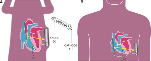
Detection of the coded signal by the anode (+) and cathode (−) of the LP. The voltage difference (v) detected by the LP is affected by the position of the LP towards the communication vector (yellow arrow). (A) Canine model with a relative small angle of the LP towards the communication vector. (B) Human model with a relative larger angle of the LP towards the communication vector. LP, leadless pacemaker.
Device orientation measurements
In both animal and human subjects device orientation was measured using ImageJ (US National Institutes of Health, Bethesda, MD, USA). Measurements were performed in the same manner in the animal and human model. The angle of the long axis of the LP is measured towards the vertical axis of 0° (α). This is used as a surrogate for the S-ICD coil, which creates the communication vector and is positioned vertically on the AP view. The human models only have one of the devices implanted, therefore the S-ICD coil was not available in LP patients to be used as a reference. The distance between the S-ICD coil and generator (ß) was measured as shown in Figure 2. Additional distances were measured using the length of the LP and the S-ICD as reference values. Distances were measured between the coil to LP (γ) and LP to the S-ICD generator (Figure 2). To determine the distance of the LP to the transmitting electrode, the S-ICD coil, the sternum was used as a reference point on the chest X-rays (γ). The device orientation measurements in the 90-day animal model were performed in the same manner as described for acute animal model. In human subjects, the first chest X-ray obtained after implantation was used, which was taken one day after implant of the device. Measurements are reported as mean with standard deviation or median with first and third quartile, interquartile range (IQR) depending on whether distribution is normal. Statistics were performed in R v.3.3.3 or IBM SPSS Statistics 24.
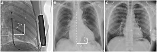
(A) AP fluoroscopy image of canine subject after LP and S-ICD implant. (B) PA X-ray of human subject post-implant. (C) PA X-ray of human subject after S-ICD implant. α, angle of LP orientation; ß, distance between S-ICD coil and shock generator; γ, distance of the LP to the S-ICD coil in canine subjects, or sternum in LP patients. AP, anterior–posterior; LP, leadless pacemaker; PA, posterior–anterior; S-ICD, subcutaneous implantable cardioverter-defibrillator.
Results
Device implantation in canine subjects
All animals but one were successfully implanted with a LP through the right femoral vein, in this one animal due to the vessel diameter the LP had to be implanted through the left femoral vein. In one animal model malfunction with the prototype catheter resulted in an aborted procedure before LP implant was attempted. In these animal models appropriate VVI functionality of the LP was seen in all models during acute performance and during a 90-day follow-up period in the selected animal models. Details of antibradycardia pacing performance are described in details elsewhere.7 The S-ICD was successfully implanted in all animal models included in this study and without complications occurring during follow-up.
Device orientation in canine subjects
In the acute experiments, 27 canine subjects were implanted with an LP and S-ICD. In 23 canine subjects, AP fluoroscopy images were available and were included in this analysis. Ten subjects were enroled in the 90-day follow-up protocol and had fluoroscopy images available. Median distance of both devices in the canine models at the time of implant and during the 90-day experiments are presented in Table 1. At the time of implant the median angle of the LP towards the communicating vector was 29° (IQR 25°–35°) with a total range between 4° and 39°. The median angle of the LP to communicating vector was 24° (IQR 21°–35°), ranging from 6° to 49° in the experiments at Day 90. The cardiac cycle movements can influence the LP orientation and could contribute to small differences between implant and 90-day follow-up on the acquired fluoroscopy images.
Device orientation measurements in canine and human subjects
| Acute canine subjects (n = 23) | Chronic canine subjects (n = 10) | Human subjects (S-ICD n = 100, LP n = 72) | |
|---|---|---|---|
| S-ICD coil to generator (β) (cm) | 10.2 (IQR 9.2–12.8) | 8.3 (IQR 8.0–11.4) | 13.4 (IQR 12.2–14.6) |
| LP to S-ICD coil (γ) (cm) | 0.8 (IQR 0.3–1.6) | 2.1 (IQR 1.1–3.3.) | 4.6 (IQR 3.9–5.6) |
| LP to S-ICD generator (cm) | 9.7 (IQR 8.1–11.7) | 9.7 (IQR 7.2–9.9) | N/A |
| LP angle to communicating vector (α) | 25° (range 4°–39°) | 24° (range 6°–49°) | 56° (range 10°–90°) |
IQR, interquartile range; LP, leadless pacemaker; N/A, not applicable; S-ICD, subcutaneous implantable cardioverter-defibrillator.
Communication thresholds in canine subjects
Intrabody communication during the acute tests was successful in all subjects. The median communicating threshold was 2.5 V (IQR 2.0–3.0 V). During the acute tests a trend towards higher thresholds was seen in subjects in which the LP angle towards the communicating vector was very small (Figure 3). Theoretically this was expected, it seems that the effect is not very large as communication was still possible although the communication threshold increased. This can be partially attributed to the fact that more than one communication message is transmitted in succession in order to take advantage of the small movements of the LP during the cardiac cycle. All communication attempts were successful during testing at 90 days and a decreased median communication threshold of 1.5 V (IQR 1.0–2.0 V) was observed (Figure 3).
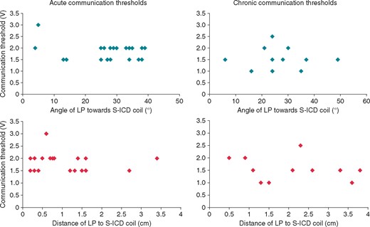
Results of communication thresholds in relation to the angle of the LP (blue) and distance of the LP to the S-ICD coil (red), during acute testing at implant and testing at 90 days post-implant. The median communicating threshold during acute testing and testing at 90 days follow-up were 2.5V (IQR 2.0–3.0V) and 1.5V (IQR 1.0–2.0V) respectively. IQR, interquartile range; LP, leadless pacemaker; S-ICD, subcutaneous implantable cardioverter-defibrillator.
Based on bench testing, the effect of the conductive communication itself on the longevity of S-ICD is so small as to be negligible, even assuming 1000 ATP requests per year from S-ICD to LP. As for the effect of ATP therapy on the battery longevity of the LP the impact is also expected to be small. Providing 1000 bursts of ATP would reduce the expected battery longevity of the LP by 1.5 week.7
Device orientation in human subjects
In the human retrospective analysis, a total of 72 LP patients and 100 S-ICD patients were included. The median angle of the LP was 56° (IQR 48°–66°). The distance of the LP to the sternum where the S-ICD coil would have been located was 4.6 cm (IQR 3.9–5.6 cm). The median distance between the S-ICD coil and shock generator was 13.4 cm (IQR 12.2–14.6 cm).
Discussion
Major findings
The major finding of this study is that we observed low communication thresholds and high success of communication from the S-ICD to the LP in an animal model even when presenting device–device orientation angles that are less than ideal for conductive communication. In addition, the human implant orientations simulated in this study projects more favourable angles and orientation for human implants as long as an appropriate anatomic implant of the S-ICD is performed. The methods used in these animal studies to assess a communication function including postural influences can now be applied to the impending human studies planned and provide orientation references. Future human studies can also gain confidence that the endpoint of communication will lead to successful delivery of ATP using the available data.4,6,7 This study also confirms that the requirements of the S-ICD sensing and defibrillation auto algorithm as well as the pacing function of the LP is unique to each patient’s anatomy and that we need to pay attention to the range in these variables. The positioning of the LP is subject to preferred pacing positions and adequate sensing and capture of the LP, therefore choice in LP positioning in sometimes limited. This data suggests the system in place here is capable of working despite two devices that anatomically do not allow for the absolute optimal positions of each device to conduct communication in a near field. Despite these challenges conductive communication remains the preferred communication method because of the low energy required for near-field communication.
Far-field vs. near-field energy requirements
Wireless radiofrequency (RF) communication is essential in the daily management of patients with cardiovascular diseases. Early use of RF connectivity to a cardiac implantable electronic device via wands in near proximity (millimetres to centimetres) and more recently by remote monitoring (metres) has incrementally improved patient outcomes with their implantable device(s) and monitors.10,11 Medical body area networks (MBANs) began with in-hospital remote telemetry in an effort to allow clinicians to access their patient’s data across the expanse of the hospital as well as provide alarms to alert caregivers of sudden changes in patient status.11 These networks have been improving in parallel along with novel medical monitoring and device technology. Early MBANs using disposable cutaneous electrode sensors as affected lower cardiovascular mortality but can be largely limited by energy resource drain (e.g. needing to change 9 volt battery often).12
In the case of hospital telemetry, the energy drain is predominantly due to far-field connectivity and the constant duration of such communication. The concept of modular therapy, as currently proposed in this article, includes a two device network in near field with intermittent communication only activated when the S-ICD discovers a tachyarrhythmia. Near field RF communication especially via an aqueous medium such as a mammal, rather than air, has a significantly lower energy resource drain.13 Human body networks, essentially in and about the thorax, are easily defined as near field communication zones with aqueous conductive properties. These zones of connectivity will require orientation and types of communication delivery that are designed to provide algorithms with reliable and improved efficacy and safety consequent to communication at low energy resource. Near field networks that are intermittently event activated consequent to the arrhythmia algorithm have the most potential and may be dependent on device–device orientation in an age of never ending energy needs.
Communication and device energy resource
A conductive communication process using RF energy on the medical bandwidth, such as used in this study, employs body tissue as a natural conductor and thus requires the least amount of energy compared with other methods of MBAN communication. This can, however, be energy inefficient depending on distance, angle and electrical requirements of the systems communicating.12,13 Such is the case with RF telemetry, the most often utilized network communicator by implanted devices and monitors but requires a wired connection that transmits through air. Radiofrequency expends more energy in order to conduct the telemetry signal making this distance and transmission field less efficient. Conductive communication is also best in this version of mCRM because the S-ICD has already allowed for conductive communication without a change in the hardware of the device. An adjustment in the firmware of the S-ICD will be necessary to enable conductive communication back to the S-ICD as a receiver of information and this is planned.
Limitations
The canine models provide valuable data on the safety and efficacy of intrabody communication between a LP and S-ICD. However, the size of the canine cohort is limited and only few canine subjects were enroled in the 90-day communication experiments. The images analysed for this study are static 2D images, which are taken while both canine and human models were in a static position. Variation in device position can occur during movement, as well as the small beat-to-beat variations of device position during the cardiac cycle. In this study, the effect of electromagnetic interference was not tested, neither was the effect of other implanted devices such as abandoned leads or electrodes, artificial valves or bone fixations. These factors could influence successful intrabody communication between the LP and S-ICD and should be explored in future studies with this technology.
No studies have been done in human subjects with simultaneous implants of a LP and S-ICD, therefore human device orientation measurements have been performed with surrogate reference points in patients with either a LP or S-ICD implanted. The effect of the thoracic distance differential between the S-ICD coil and shock generator in the human subjects on the intrabody communication has yet to be determined and is not performed in this study.
Future perspectives
The future potential of a mCRM system with an S-ICD communicating bidirectionally with a LP or other implanted nodes is promising. Rhythm and rate feedback directly from the LP to the S-ICD could eliminate double-counting/T-wave oversensing and decrease inappropriate shock therapy. The anatomy of the human heart and thorax can be considered suitable for successful intrabody communication between a LP and S-ICD. As we spare the intravascular and cardiac space complex invasion, this system could provide both cardiac pacing and defibrillation. Further, our inability to predict exactly which pacemaker patients will need defibrillation therapy in the future, and vice versa, is an impediment to either devices adoption clinically. This modular concept can reduce implantation of unnecessary invasive hardware. Patients with an indication for either a LP or S-ICD can be implanted with the needed device after which a patient tailored therapy can be designed, with subsequent implantation of a complementing device if an indication for additional device therapy arises in the future. This step-wise modular approach to device therapy provides more therapy options for individual patients. Considering the developments in the field of dual-chamber leadless pacing, a mCRM system which includes cardiac resynchronization therapy is not unthinkable.14
Conclusion
Despite the less favourable LP orientation towards the communication vector, all communication attempts were successful in the canine subjects in acute testing and testing at 90-days. During acute tests a trend towards a higher threshold was observed in subjects with a small angle of the LP towards the communicating vector. In the human subjects, we observed a greater angle of orientation and in theory a more favourable LP position towards the communication vector. These data suggest suitability of human anatomy for conductive intrabody communication between a LP and S-ICD for mCRM and sets the stage for methods to test it.
Conflict of interest: A.B.E.Q. has nothing to disclose; F.V.Y.T. received consultancy fees from Abbott and Boston Scientific (small); B.E.K. is an employee of Boston Scientific Corp.; A.A.M.W. is a member of Scientific Advisory Committee LivaNova (modest); R.E.K. received consultancy fees and research grants from Medtronic, Boston Scientific and Abbott (significant); M.C.B. received consultancy fees from Boston Scientific (modest) and research grants from Abbott, Medtronic and Boston Scientific (significant).
