


Abstract
We report on our experience with complete mitral isthmus conduction block achieved inadvertently during radiofrequency (RF) catheter ablation for a left lateral concealed accessory pathway (AP) mimicking concentric retrograde activation. This rare condition should be acknowledged to avoid misdiagnosis of another concomitant AP and to avoid RF applications in inappropriate areas.
Case report
A 43-year-old woman underwent electrophysiology study for recurrent palpitations. No signs of preexcitation were present on the resting ECG. As a standard, three catheters were placed through the right femoral vein and positioned in the right ventricular apex, His bundle region, and into the coronary sinus (CS). A left lateral concealed accessory pathway (AP) was readily diagnosed with retrograde activation with a short ventriculoatrial (VA) interval in distal CS signal. Ortodromic atrioventricular reciprocating tachycardia (oAVRT) of 178 b.p.m. was inducible by incremental atrial pacing. An ablation catheter (4 mm tip Celsius ® , C curve, Biosense Webster, Inc.) was introduced through the right femoral artery. Mitral annulus (MA) was mapped via trans -aortic approach until the shortest VA interval of 70–80 ms during the right ventricular apical pacing was achieved ( Figure 1 A ). Unfortunately, the ablation catheter dislodged in the seventh second of the first radiofrequency (RF) application. After repositioning of the ablation catheter at the lateral part of MA, the second RF application was commenced, but nothing happened with the retrograde conduction after 20 s of RF delivery. During the third RF application slightly anterior to the previous ablation spot, the VA interval began to prolong, exhibiting a concentric activation sequence along the CS ( Figure 1 B ). Yet, the timing of atrial activation in the ablation catheter after RF delivery was still earlier than in proximal CS. Moreover, the VA conduction interval was not decremental during programmed ventricular stimulation and oAVRT was still inducible, which was suggestive of another concomitant AP or another ‘limb’ of the former AP. For ‘security’ reasons, all parts of the tricuspid annulus were briefly mapped to exclude the presence of any right-sighed AP. When the ablation catheter was positioned back into the aortic root, an early activation of anteroseptal region of the left atrium (LA) was noted ( Figure 2 A ), in concordance with previously registered signals on the last RF spot ( Figure 1 B ). Further mapping of the MA during ventricular pacing revealed that anterolateral region of the LA is still first activated and the LA was electrically excited from the lateral point in the counterclockwise direction ( Figure 2 B ). Another RF application at the anterolateral part of the MA completely abolished any retrograde conduction ( Figure 1 C ).
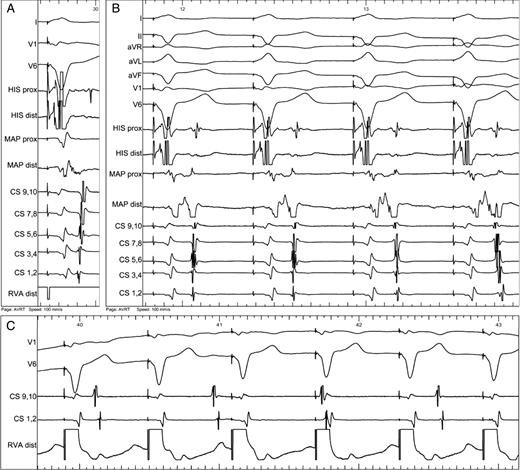
( A ) Activation sequence during right ventricular pacing. Short ventriculoatrial interval showing activation of the left atrium by retrogradely conducting accessory pathway at lateral part of mitral annulus (first activation in distal CS 1,2). Almost merged ventricular and atrial signals are recorded from the ablation catheter (MAP). ( B ) During radiofrequency energy application, gradual change of the activation sequence was observed from prolongation of the VA interval (first three beats) to complete change of activation sequence (last beat). Note that the timing of atrial activation in the ablation catheter was still earlier than in the proximal CS (CS 9,10). ( C ) Complete ventriculoatrial dissociation during right ventricular apical pacing at the end of procedure.
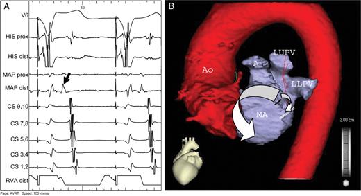
( A ) Ablation catheter (MAP) is positioned in the left coronary cusp. Note the early activation of anteroseptal region of the left atrium (black arrow) during retrograde conduction. ( B ) CT scan of the left atrium and aorta with schematic drawing of retrograde activation of the left atrium (white arrows). The impulse propagates via the accessory pathway (black line) downwards to the line of mitral isthmus block (double white line) and simultaneously upwards, passing through the left atrial roof and continuing along the interatrial septum and right pulmonary veins to the low posteroseptal region, thus mimicking concentric retrograde activation (see also A ). Ao—aorta, A—auricle, LUPV—left upper pulmonary vein, LLPV—left lower pulmonary vein, MA—mitral annulus.
Complete mitral isthmus block achieved by the first three RF ablations at the lateral MA was considered as a reason for the observed phenomenon. Mitral isthmus block was subsequently proven by typical pacing manoeuvres ( Figure 3 ). The distance between the left lower pulmonary vein and MA was measured on a CT scan performed the day after procedure (23.3 mm).
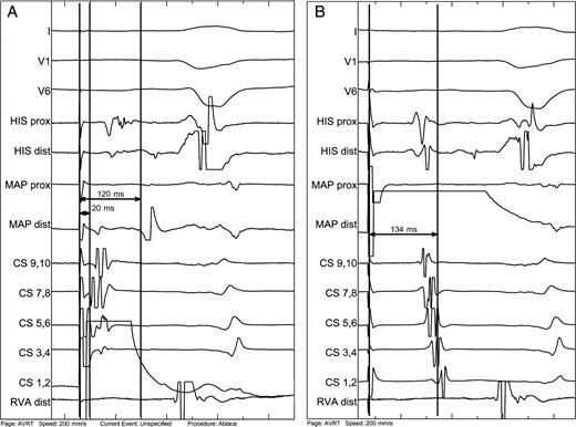
Proof of mitral isthmus block. ( A ) Pacing from the distal coronary sinus (CS 1,2) placed inferior to the mitral isthmus line of block leads to double spike signal on the line of mitral isthmus recorded at the ablation catheter (MAP), which is positioned endocardially on the line of block. The first spike is 20 ms from the stimulus, whereas the second is delayed by 120 ms—the time that the impulse needs to encircle left atrium in the clockwise direction (see also Figure 2 B ). ( B ) Similar pacing manoeuvre from the ablation catheter, which is now placed superior to the line of block. The impulse needs 134 ms to propagate in the counterclockwise direction around the mitral annulus to reach the distal CS. Note additionally the concordant septal activation indicated by His recording.
Discussion
The true atrial insertion of the AP must have been superior to initial RF applications, which inadvertently caused mitral isthmus block leaving the conduction through the AP intact and preventing activation wavefront from propagating inferiorly. Instead, the LA was activated upwards, passing through the LA roof and continuing downwards along the interatrial septum and right pulmonary veins to the low posteroseptal region ( Figure 2 B ). Alternatively, we may speculate about two limbs of the AP, the first have been abolished by the initial RF applications at the lateral MA and the second by the last RF ablation superior to the previous site. Nevertheless, it cannot explain concentric-like retrograde atrial activation recorded in the CS catheter.
Mitral isthmus block was proven by typical pacing manoeuvres with the ablation catheter positioned at the lateral part of the MA and pacing from both sites of the line of block ( Figure 3 ). A high-speed helical CT scan of the LA and pulmonary veins with minimized X-ray exposure was performed to establish the reason for relatively easy achievement of mitral isthmus block, since this is known to be a very challenging procedure during RF ablation of atrial fibrillation. Although we expected a short isthmus, no gross anatomical abnormalities were detected. The distance between the left lower pulmonary vein and MA was sufficiently long. Therefore, induction of mitral isthmus block occurred absolutely unexpectedly. In our opinion, the best explanation might be presence of areas of pre-existing functional block or scar tissue.
In conclusion, care must be taken to avoid useless mapping of the mitral or tricuspid annulus during RF ablation for left lateral AP in rare cases, when mitral isthmus conduction block occurs. Since retrograde activation of the LA resembles that of concentric conduction via His bundle, it is mandatory to prove decremental conduction properties after presumed successful RF ablation of the pathway.
Conflict of interest: none declared.
