


Abstract
The vibrational fluidized bed is innovatively adopted to regenerate the particulate filter medium for the purification of crude synthesis gas from the coal gasification process. Characteristic research of vibrated fluidized beds during dust-containing particulate filter medium regeneration has been carried out. The ideal transport model of particulate filter medium on the distributor is established and verified by using experiments. The mean residence time of the particulate filter medium can be reduced by 72% from 5.5 to 1.5 min with an increase in the working frequency from 50 to 60 Hz. The thickness of the bed layer is linearly increased with the feeding rate of the particulate filter medium under ideal working conditions. The resistance models of the fluidizing air are built up and validated, and they can be used to calculate the pressure drop of the static bed layer of the particulate filter medium on the fluidizing air distributor, which is the maximum value of the dynamic bed layer with the same thickness. The fluidizing air makes the mean residence time of the particulate filter medium decrease by 50% and reduces the difference in the particulate mean residence time under different feeding-rate conditions. The regeneration effect of dust-containing filter medium particles in a vibrated fluidized bed is evaluated. Fluidizing air with superficial velocity ranging from 0 to 0.6~0.9 m·s–1 makes the regeneration efficiency increase from 29.41% to 70.59~88.24%. This article provides a reference for the industrial application of a vibrated fluidized bed for the particulate filter medium recycling system.
Introduction
A vibrated fluidized bed (VFB) [1] is a type of fluidization equipment with vibration function for the processing of particulate material processing, which has the advantages of a large contact area of the gas–solid phase, a low bed pressure drop and critical fluidization velocity of the bed, uniform structure of the bed layer and easy, stable unit operation. Due to the structural characteristic of a VFB, the defects of the conventional fluidized bed are effectively reduced, such as high superficial velocity, constrained heat transfer coefficient of the gas–solid phase [2], abnormal slugging and so on. Thus, VFBs can be commonly used in many large-scale industrial processes including traditional screening, fractional humidity control [3], drying and granulation [4, 5]. A wide range of raw materials are processed by VFBs, which can be fuel [6, 7], inorganic non-metallic materials, chemicals [8, 9], biochemical products [5, 10, 11], expanded feed, food [12] and so on. Current theoretical studies on VFBs mainly include kinematic analysis [13–15], modelling of particle flow type on a VFB distributor [16, 17], stratification and segregation of binary particles in the bed layer [18–20], heat transfer analysis of the multiphase flow [2, 21], fluidization quality [22] analysis based on a porous medium model and stability optimization of operational factors [19, 23, 24].
Based on the small and medium-scaled coal gasification process of the National Institute of Clean-and-Low-Carbon Energy, a dedusting system of a granular filter bed is developed to purify crude synthesis gas. This paper innovatively uses VFB equipment to regenerate and recycle the dust-containing filter medium from the dedusting system. The dust-containing filter medium can be separated in the VFB and the regenerated filter medium is returned to the dust-removal equipment for reuse. The dropped dust is conveyed to the bag dust collector via the gas phase. The regeneration effect of the dust-containing filter medium in VFBs has not been reported so far. Therefore, it is necessary to study the transport and separation characteristics of the dust-containing filter medium in VFB equipment, in order to provide a reference for the industrial application of the filter medium recycling system in the process of synthesis gas purification.
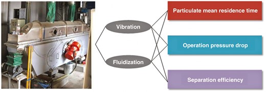
Taking the filter medium and VFB equipment as the research object, the transport model of the filter medium particles in the VFB and the resistance model of fluidizing air were established and verified by using experiments. The effect of the VFB working frequency on the mean residence time (MRT) of the filter medium particles was investigated. In addition to that, another two important issues were also involved: the relationship between the thickness of the bed layer and the VFB working load—that is, the feeding rate of the filter medium particles; and the relationship between the operating pressure drop and the superficial gas velocity of the fluidizing air in the VFB equipment. In addition, the separation and regeneration effect of the dust-containing filter medium in the VFB was evaluated and the VFB operation space was obtained. The research has guiding significance for industrial amplification of the filter medium recycling system in the synthesis gas purification unit.
1 Equipment and material
To study the transport and regeneration characteristics of dust-containing filter medium particles in the VFB equipment, the experiment apparatus was constructed; the flow chart is shown in Fig. 1. The dust-containing filer medium particles regeneration system is mainly composed of a quantitative feeding system and a VFB separation processing subsystem. The feeding rate of the dust-containing filter medium can be controlled by the feeding system [25]. The input dust-containing filter medium can be regenerated in the VFB equipment. The regenerated filter medium is returned to the dust-removal equipment for reuse. The dropped dust is conveyed to the bag dust collector via the gas phase.
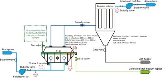
The process of the regeneration of the dust-containing filter medium for purification of crude synthesis gas
According to the design of the feeding system [25], when the working current of the feeder system Ifeeder is adjusted from 1.0 to 1.6 A, the feeding rate of the filter medium Ffeed increases from 641.90 to 1245.75 kg·h–1.
The shape, structure and size of the VFB equipment is described in Fig. 2a. This device consists of three interfaces of solid material: the raw material inlet ① of the dust-containing filter medium particles, the outlet ② of the regenerated filter medium particles and the discharge port ③ for cleaning the fluidizing air chamber ⑥. The discharge port ③ is closed during the normal state and operation, except that a small amount of residual material is discharged when the fluidized air chamber ⑥ is cleaned. In addition, the VFB equipment also contains four interfaces of the gas phase: two inlets ④ of fluidizing air and a pair of dust exhaust outlets ⑤. It is important to note that the VFB is an isolated device that is always vibrating during normal operation. Thus, all the interfaces of the solid material and gas flow mentioned above need to be connected by soft connections to the corresponding particle feeding system and discharging system. The feeding system contains the feeding of dust-containing filter medium and the fresh fluidizing air. The discharging system includes the collection of the regenerated filter medium and the clarification of the exhaust gas. The entire VFB unit should be located on four soft rubber abutments, as shown in Fig. 2b.
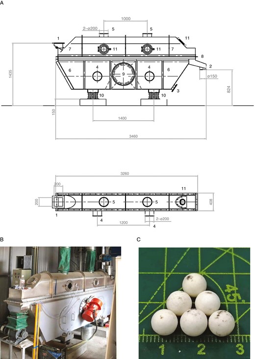
Experimental equipment of the vibrated fluidized bed (VFB). (a) Schematic diagram of the structure and dimension: ① feeding inlet of raw materials; ② discharge port of products; ③ discharge port from wind chamber; ④ inlet of fluidizing air; ⑤ outlet of fluidizing air; ⑥ chamber of fluidizing air; ⑦ separation room; ⑧ distributor of fluidizing air; ⑨ vibration motor; ⑩ rubber supports; ⑪ observation window. (b) Realistic image of the experimental equipment of the VFB. (c) Dust-removal medium particles with a diameter of 6 mm.
The interior of the whole VFB equipment is divided into the separation room ⑦ and the fluidizing air chamber ⑥ by the fluidizing air distributor ⑧, whose aperture diameter is ~1.5 mm and aperture ratio is ~0.128. The fluidizing air enters the fluidizing air chamber ⑥ from the gas inlet ④, carries the dust powder dropped off from the dust-containing filter medium particles transported on the fluidizing air distributor ⑦ and flows into the subsequent purification device of the exhaust gas through the outlet ⑤. The dust-containing filter medium particles that have entered by the raw material inlet ① are separated by the fluidizing air and the vibration of the fluidizing air distributor ⑧, and transported horizontally throughout the outlet ② to be collected and recycled again.
The vibration motion of the device is driven by a pair of vibrating motors ⑨ (2 × 0.8 kW) mounted on both sides of the fluidizing air chamber ⑥. The working frequency of the vibrating motors ⑨ is controlled by using a variable frequency regulator (0~60 Hz). The running state of the dust-containing filter medium particles on the fluidizing air distributor ⑧ inside the VFB equipment can be observed through five observation windows ⑪.
The experimental filter medium particles are spherical high-alumina ceramic balls with a diameter of 6 mm and particle density of 3.8 g·cm–3, as shown in Fig. 2c, which are mainly used to investigate the transport characteristics including the MRT and operation pressure drop on the VFB distributor. The surfaces of the filter medium particles are attached to the dust scattered in the crude synthesis gas in the equipment of the granular bed filter. The dust-containing filter medium particles are used to investigate the regeneration results in the VFB equipment.
For the measurement of the particulate MRT on the VFB distributor, the following methods are used in this experiment. (i) Start the VFB equipment and adjust the working frequency fVFB to the specified value, such as 45, 50, 55 or 60 Hz. (ii) Turn on the feeding system and adjust the working current Ifeeder to the specified value, such as 1.0, 1.2, 1.4 or 1.6 A. (iii) Measure the quality of the filter medium particles flowing out of the outlet of the VFB equipment at the same time interval, such as 30 s, to determine whether or not the VFB equipment is in a steady condition. (iv) In a steady condition, stop the feeding system and start timing. Get the first time point t1 at which the flow rate at the outlet of the VFB equipment starts to decrease. Get the second time point t2 when the VFB equipment stops discharging. Thus, the average of t1 and t2, that is (t1 + t2)/2, can be considered approximately as the MRT of the filter medium particles τ under the specific working conditions.
2 Hypothesis and modelling
It is necessary to establish and verify the relationship between the thickness of the bed layer and the VFB operating conditions to evaluate the pressure drop of the fluidizing air during the regeneration process of the dust-containing filter medium particles in the VFB. Therefore, an ideal 1D transport model of the particulate material in the VFB is built up based on the assumptions as follows.
(i) The particulate material uniformly moves along the length direction of the VFB distributor. The mass flow rate of particulate material transported on the rectangle distributor can be calculated as:
where Fs is the mass flow rate of the particulate filter medium, in kg·s–1; Gs is the mass velocity of the particulate filter medium, in kg·m–2·s–1; ρs is the particle density of the filter medium, in kg·m–3; us is the particle velocity along the length direction of the rectangle distributor, in m·s–1; A represents the flux area of the particulate filter medium, in m2; b is the width of the rectangular distributor, in m; Ls is the thickness of the particulate layer on the VFB distributor; and ε is the static bed layer porosity of the particulate material in the VFB equipment.
(ii) The back-mixing or axial diffusion phenomenon along the length direction is ignored. Thus, the MRT of the particulate filter medium can be calculate as:
where τ represents the MRT of the particulate filter medium, in s; and a is the length of the rectangular distributor, in m.
(iii) Under the normal VFB working conditions, the transport velocity of the particulate material on the VFB distributor us has a relationship with the VFB working frequency fVFB, the feeding rate Ffeed and the superficial velocity of the fluidizing air ug:
where fVFB represents the working frequency of the VFB equipment, in Hz; Ffeed (≤Fs) is the feeding rate of the particulate filter medium, in kg·s–1; and ug is the superficial velocity of the fluidizing air, in m·s–1.
3 Experimental validation
3.1 MRT
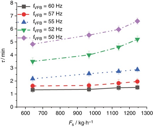
In this experiment, the MRT of the filter medium particles on the VFB distributor with different feeding rates was measured under different working frequencies, as shown in Fig. 3.
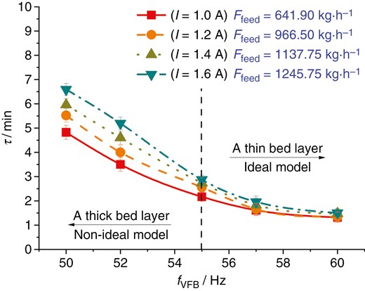
The MRT of the filter medium particles on the VFB distributor affected by the VFB working frequency under the different feeding amounts of the VFB equipment
It is not difficult to conclude from Fig. 3 that the VFB working frequency fVFB has a direct and significant effect on the MRT of the filter medium particles τ. A higher VFB working frequency causes the filter medium particles to move more quickly on the fluidizing air distributor, which consequently affects the particulate MRT. It is worth noting that the particulate MRT is not only affected by the VFB working frequency, but also influenced by the feeding rate of the filter medium particles. The particulate MRT is only related to the VFB working frequency, such as 55~60 Hz, and has almost nothing to do with the particulate feeding rate. The influence of the particulate feeding rate is remarkable, especially when the VFB working frequency is lower than ~55 Hz, which is vividly shown in Figs 3 and 4. The difference in the particle MRT is more obvious under the conditions of a relatively low VFB working frequency, especially when the feed rate of the filter medium particles is higher.
Effect of the feeding amount of the filter medium particles on the particulate MRT under different conditions of the VFB working frequency
Due to the limitations of the actual situation or measurement method, the test results shown in Figs 3 and 4 can be analysed specifically, as follows. As validated in the experiment, a certain thickness of the filter medium bed layer is accumulated on the vibrating fluidizing air distributor, especially under the condition of a larger particulate feeding rate and a lower VFB working frequency. The effect of the back-mixing or axial diffusion phenomenon of the filter medium particles on the length direction of the VFB distributor is more obvious. A thin particulate bed layer is more similar with the plug flow on the VFB distributor according to the basic assumption of the VFB transport model as shown in Equation (1) under the condition of a smaller particulate feeding rate and a higher VFB working frequency.
3.2 Operation line of the VFB
Based on the establishment of the particle transport model, it is not difficult to conclude that the thickness of the particulate layer on the VFB distributor is related to both the VFB working frequency and the feeding rate of the filter medium particles, which also affect the particulate MRT on the VFB distributor, as described in Section 4.1. Therefore, the experimental results can naturally verify the relationship between the operation parameter of the VFB working frequency and the design parameters of the particulate layer thickness and MRT on the VFB distributor, as shown in Fig. 5.
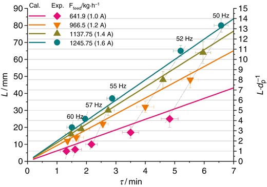
: Validation of the transport model of the filter medium particles on the VFB distributor predicting the relationship between the thickness of the bed layer and the particulate MRT in the VFB equipment
It can be seen from Fig. 5 that the thickness of the particulate bed layer is linearly increasing with the particulate MRT under the conditions of different VFB working frequencies but a fixed particulate feeding rate. According to the VFB equipment test data, the operation line with a constant working frequency can be fitted, a higher slope of which can prove that the MRT of the filter medium particles has almost nothing to do with the particulate feeding rate. In other words, the operation line is approximately perpendicular to the direction of the axial of the MRT under the condition of a higher VFB working frequency, such as 60 Hz. On the contrary, the operation line is inclined in the direction of the axial of the MRT at the lower VFB working frequency, such as 50 Hz. Therefore, it can be concluded that the MRT difference due to the variance of the particulate feeding rate is more obvious under the relatively low VFB working frequency, especially when the feeding rate of the filter medium particles is larger.
3.3 Analysis of fluidization property
3.3.1 Resistance of the fluidizing air distributor
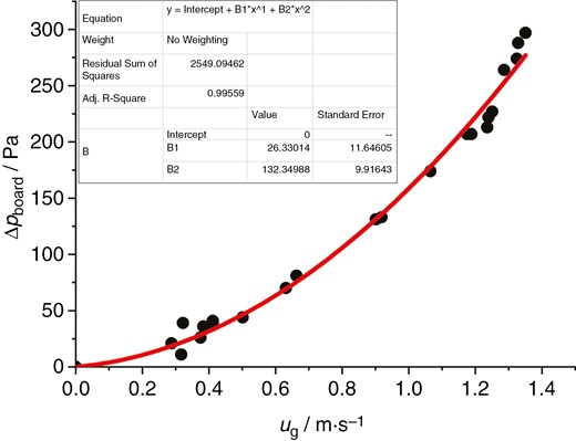
The fluidizing air distributor in the VFB equipment is a strip rectangular plate with an opening hole diameter of 1.5 mm, an opening hole distance of 4 mm and an opening rate of 0.1275. Fluidizing air in the VFB equipment is adjusted by the opening of the butterfly valve on whose pipeline the pressure drop can be easily measured at different superficial gas velocities, as shown in Fig. 6.
: Calculation of the resistance of the VFB distributor
Through linear fitting, the relationship between the pressure drop of the fluidizing air distributor in the VFB equipment and the superficial gas velocity of the fluidizing air is shown in Equation (2):
It can be seen from the experimental data and the fitting results that the relationship between the pressure drop of the fluidizing air distributor in the VFB equipment and the superficial gas velocity conforms to the law of the quadratic curve. Under the experimental conditions, the maximum air resistance of the fluidizing air distributor in the VFB equipment is ~300 Pa.
3.3.2 Resistance of the static bed layer of the filter medium particles
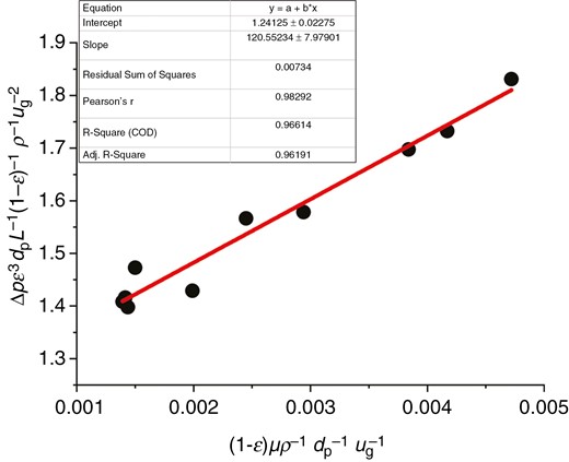
The operation pressure drop of the VFB equipment is caused not only by the resistance of the fluidizing air distributor, but also by the bed layer of the filter medium particles on it. The recycled filter medium particle is spherical with diameter of 6 mm and density of 3572.50 kg·m–3, as shown in Fig. 2c. The operation pressure drop is the upper limit under the same thickness of the static bed layer of the filter medium particles. Therefore, research on the resistance of the static bed layer of filter medium particles is carried out in this experimental work. The Ergun equation is employed to describe the static bed resistance model:
The parameters A and B can be fixed through experimentation, as illustrated in Fig. 7:
Calculation of the resistance of the static bed layer of the filter medium on the VFB distributor
The relationship between the resistance of the static particulate bed layer and the superficial gas velocity is obtained by linear fitting, where two important parameters in the Ergun equation are 120.55 and 1.24, as shown in Equation (7):
Equation (7) can be used to calculate the operation pressure drop of the fixed bed and be simplified to Equation (8) for Rep = dpρu/μ < 20:
The operation pressure drop of the fluidized bed can be calculated by using Equation (9):
Therefore, it is not difficult to evaluate the critical fluidizing air velocity of the filter medium particles umf through using Equation (10):
The umf of the filter medium particle is about 43.22~52.54 m·s–1. Factually, the bed layer of the filter medium particles cannot be fluidized by the operational superficial velocity of the VFB equipment, ranging from 0.0 to 1.5 m·s–1. Therefore, the loosening of the particulate bed layer is dependent on the vibrating motion of the VFB equipment. Thus, the Ergun equation can evaluate the upper limit of the pressure drop of the particulate bed layer with the same thickness in the vibrating state.
3.3.3 Influence of operating parameters on fluidization properties in the VFB
The VFB working frequency and the particulate feeding rate are considered to be two important operating parameters affecting the fluidization properties of the VFB equipment, which include the pressure drop and the MRT of the filter medium particles.
Particulate feeding rate.
The influence of the feeding rate of the filter medium particles on the pressure drop of the fluidizing air and the particulate MRT in the VFB equipment is investigated at a certain VFB working frequency, which is illustrated in Fig. 8. The dynamic pressure drop in the bed layer and the MRT of the filter medium particles are affected by the superficial velocity of the fluidizing air under the condition that the VFB working frequency is fixed at 55 Hz and the particulate feeding rate is set at 641.90, 1137.75 and 1245.75 kg·h–1, respectively.
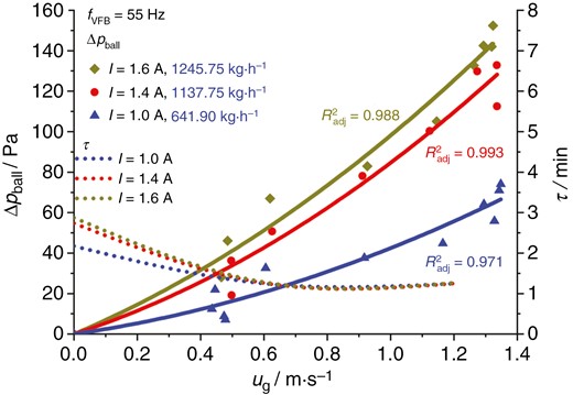
Effect of the feeding amount of filter medium particles on the fluidization pressure drop and the particulate MRT on the VFB distributor
The measurement results show that the relationship between the dynamic pressure drop in the bed layer Δpball and the superficial velocity of the fluidizing air ug is approximated as a quadratic curve, which was established similarly on the static bed layer.
It is worth noting that the particulate MRT of different feeding rates of filter medium particles tends towards consistent under the influence of fluidizing air. In other words, the existence of fluidizing air decreases the effect of the particulate feeding rate on the MRT of the filter medium particles, which means that the particulate MRT is only related to the VFB working frequency. As vividly shown in Fig. 8, a relatively low superficial gas velocity of fluidizing air ug affects the particulate MRT slightly. With an increase in ug (0~0.45 m·s–1), the particulate MRT decreases by 30~50%. However, at relatively high ug (≥0.45~1.00 m·s–1), the particulate MRT is not changed significantly and maintains 30~50% of the value in the VFB equipment without fluidizing air. At this time, the MRT is not only independent of ug, but also unrelated to the feeding rate of the filter particles Ffeed.
In addition, the thickness of the dynamic bed layer increases with the feeding rate of the filter medium particles under the fixed VFB working frequency, which can also can be concluded from Fig. 8.
Working frequency of the VFB.
The effects of the VFB working frequency on the pressure drop of the dynamic particulate bed layer and the MRT of the filter medium particles have been investigated with a fixed particulate feeding rate of 1137.75 kg·h–1. When the VFB working frequency is set at 50 and 55 Hz, respectively, the effect of the superficial velocity of the fluidizing air ug on the pressure drop of the dynamic particulate bed layer and the MRT of the filter medium particles in the VFB equipment is measured, as shown in Fig. 9. The results show that the relationship between the pressure drop of the dynamic particulate bed layer Δpball and the superficial velocity of the fluidizing air ug is approximated as a quadratic curve. The higher the VFB working frequency, the thinner the particulate bed layer. Thus, the operation pressure drop is lower than that under the condition of a lower VFB working frequency.
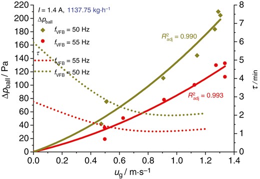
Effect of VFB working frequency on the fluidization pressure drop and MRT of the filter medium particles on the VFB distributor
It is important to note from Fig. 9 that the MRT of the filter medium particles in the VFB equipment is significantly affected by the superficial velocity of the fluidizing air ug ranging from 0 to 0.45 m·s–1, which is decreased by almost 50%. However, a relatively high ug (≥0.45~1.00 m·s–1) cannot influence the particulate MRT effectively, which is basically maintained at 50% of the state without fluidizing air. In other words, a relatively low superficial gas velocity has a greater influence on the particulate MRT on the VFB distributor but, at relatively high superficial gas velocity, it leads to the remarkable dependence of the particulate MRT on the VFB working frequency. Because of the higher VFB working frequency leading to the higher conveying rate of the filter medium particles, a short particulate MRT will occur when the superficial gas velocity becomes not so important to that.
Based on the above experimental results as shown in Figs 8 and 9, it can be seen that the VFB working frequency has a greater influence on the particulate MRT than the superficial gas velocity of the fluidizing air, which is still one of the most important operating factors.
3.4 Regeneration of the dust-containing filter medium
3.4.1 Single effect of the VFB working frequency
The single factor effect of the VFB working frequency on the regeneration of the dust-containing filter medium particles evaluating the separation characteristics of the VFB equipment is analysed. The profile of the mass fraction of dust powder in the filter medium along the length direction of the air distributor of the VFB equipment is investigated when the VFB working frequencies are 60, 55 and 50 Hz, respectively.
The experimental raw material is particulate filter medium with a dust content of 8.5%. The dust content of the particulate filter medium is measured at distances of 1.0, 2.0 and 3.0 m (outlet) from the inlet of the VFB equipment when the VFB working frequency is 60, 55 and 50 Hz, respectively. The experimental measurement results can be described as shown in Fig. 10. In a steady-state condition, samples are randomly selected at each measuring point to analyse the dust content of the particulate filter medium, whose mean value and error limits are obtained.
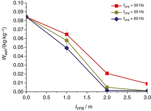
Single effect of the VFB working frequency on the separation efficiency of the dust-containing filter medium along the length of the VFB equipment
It is easy to see from Fig. 10 that the mass fraction of dust content in the particulate filter medium gradually decreases along the length of the VFB distributor, which is almost zero at the outlet of the VFB equipment where the regeneration efficiency is almost 100%. In addition, the closer the VFB equipment, the larger the measurement error of the upper and lower limits of the dust content.
According to the results of the above research, the working frequency of the VFB directly affects the regeneration efficiency of the dust-containing filter medium particles. When the feeding rate of the dust-containing filter medium particles is fixed, the thickness of the bed layer and particulate MRT on the VFB distributor is indirectly affected by the VFB working frequency. As shown in Fig. 10, when the VFB working frequency is 60 Hz, the processing capacity of the VFB equipment is relatively higher. The thickness of the bed layer is thinner at the time. Although the particulate MRT is short, the regeneration efficiency of the dust-containing filter medium particles is excellent. It is not difficult to observe that the dust is easily separated from the raw filter medium and the particulate MRT in the VFB distributor is not an important operation factor compared with the VFB working frequency. Separation of the shed dust and the pure filter medium is an essential problem on the VFB distributor. Therefore, a thinner bed layer makes dropped dust through the gap between the neighbouring particles and the holes of the VFB distributor easier. The dust dropped enters the air chamber through the holes of the air distributor and the pure filter medium is collected at the outlet of the VFB equipment device.
3.4.2 Compound effects of the VFB working frequency and fluidizing air
An important conclusion from the regeneration experiment with a single effect of the VFB working frequency is that the dust is easily detached from the raw filter medium and the two-phase separation between the dropped dust and the pure filter medium is the key factor affecting the regeneration efficiency of the dust-containing filter medium particles. In the actual operation process, the fluidizing air not only assists the particle fluidization of the dust-containing filter medium particles, but also promotes the detachment of dust from the surface of the filter medium and further promotes the two-phase separation of the shed dust and the pure filter medium.
In the separation experiment with compound effects of the VFB working frequency and fluidizing air, the raw material still uses the dust-containing filter medium particles with a dust content of ~8.5% and the VFB working frequency is set at 55 Hz. The dust content distribution along the length direction of the VFB distributor is investigated when the superficial velocity of fluidizing air is 0, 0.6 and 0.9 m·s–1, respectively. The results can be described as shown in Fig. 11. In a steady-state condition, samples are randomly selected at each measuring point to analyse the dust content of the dust-containing filter medium particles, and the mean value of the dust content and the upper and lower limits of error are obtained.
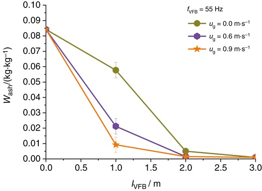
Compound effects of the VFB working frequency and superficial velocity of the fluidizing air on the separation efficiency of the dust-containing filter medium along the length of the VFB equipment
It can be seen from Fig. 11 that the fluidizing air has a significant impact on the separation efficiency and regeneration effect of the dust-containing filter medium particles. It is not difficult to see that, at the sampling point of 1.0 m away from the inlet of the VFB equipment, the dust content is significantly reduced by 70.59~88.24% compared with the condition without fluidizing air. Fluidizing air with a superficial velocity ranging from 0 to 0.6~0.9 m·s–1 can increase the regeneration efficiency rise from 29.41% to 70.59~88.24% at a distance from the entrance of 1.0 m, as shown in Fig. 11, although the regeneration efficiency is nearly the same at the outlets of the VFB equipment. Therefore, we can conclude that fluidizing air can reduce effectively the design length of the VFB equipment. In conclusion, the superficial gas velocity of the fluidizing air is very conducive to the two-phase separation of the shed dust and the pure filter medium.
4 Conclusion
Based on the small and medium-scaled coal gasification process developed by the National Institute of Clean-and-Low-Carbon Energy, the equipment of the VFB is innovatively employed to recycle the dust-containing filter medium particles for purifying the crude synthesis gas. This research analyzes the phenomena of particulate transport and two-solid-phase separation on the VFB distributor, and important conclusions can be summarized as follows:
(i) The ideal transport model of the particles of the filter medium is established in the VFB distributor and the influence of the VFB working frequency on the particulate MRT is investigated. The MRT of the particulate filter medium can be reduced by 72% from 5.5 to 1.5 min with an increase in the working frequency from 50 to 60 Hz. The thickness of the bed layer is linearly increased with the feeding rate of the particulate filter medium under the ideal working conditions. The experimental results show that when the VFB working frequency is relatively large (such as 60 Hz), the particulate filter medium on the VFB distributor is close to the ideal plug flow movement; the particulate MRT is only approximately related to the VFB working frequency and has nothing to do with the particulate feeding rate. When the VFB working frequency is relatively small (such as 50 Hz), the type of filter medium on the VFB distributor is far from the ideal plug flow movement because of the axial diffusion phenomenon. At this time, the particulate MRT is related not only to the VFB working frequency, but also to the feeding amount of the filter medium particles.
(ii) The resistance models of the fluidizing air are built up and validated, and they can calculate the pressure drop of the static bed layer of the particulate filter medium on the fluidizing air distributor, which is the maximum value of the dynamic bed layer with the same thickness. Fluidizing air indeed reduces the particulate MRT by 50% and makes it tend to be consistent under different feeding amounts of filter medium particles. The VFB working frequency has a greater influence than the superficial gas velocity of fluidizing air on the particulate MRT, the thickness of the dynamic bed layer and the operation pressure drop.
(iii) The separation characteristics of dust-containing filter medium particles in the equipment of a VFB is also validated factually. The results show that the regeneration efficiency increases gradually along the length direction of the VFB equipment, the exit of which is ≤99%. Fluidizing air with a superficial velocity ranging from 0 to 0.6~0.9 m·s–1 changes the regeneration efficiency from 29.41% to 70.59~88.24%.
In this research, three aspects of the operation characteristics of the VFB equipment have been validated containing the particle transport, fluidization and two-solid-phase separation. Especially, the ideal model of particle transport on the VFB distributor can be validated by the condition of a high VFB working frequency in the experiment. However, the prediction bias of the ideal model occurs under the low VFB working frequency because the VFB working load affects the particulate flow in the VFB distributor remarkably. Therefore, the modification of the ideal transport model should involve the factor of the feeding amount of the dust-containing filter medium particles in the next research. This study provides important guiding significance and reference value for the industrial process design and operation of the particulate filter medium recycling system for crude gas purification.
Nomenclature
| Symbol | Meaning |
|---|---|
| a | length of the fluidizing air distributor of VFB equipment (3.0 m) |
| A | a parameter in the Ergun equation (–) |
| As | cross-sectional area of the particulate material flow in the VFB equipment (m2) |
| b | width of the fluidizing air distributor of the VFB equipment (0.3 m) |
| B | a parameter in the Ergun equation (–) |
| dp | diameter of the filter medium particle (6 mm) |
| fVFB | working frequency of the VFB equipment (Hz) |
| Fs | handling capacity of the particulate material in the VFB equipment (kg·s–1) |
| Ffeed | feeding rate of the feeder system of the dust-removal medium (kg·s–1) |
| g | gravity acceleration (9.81 m·s–2) |
| Gs | mass flow velocity of the particulate material in the VFB equipment (kg·m–2·s–1) |
| Ifeeder | working current of the feeder system of the dust-removal medium (A) |
| Ls | static bed layer thickness of the particulate material (m) |
| ms | mass of the particulate filter medium on the VFB distributor (kg) |
| Δp | operation pressure drop of the fluidized bed (Pa) |
| Δps | pressure drop of the static particulate layer in the fixed bed (Pa) |
| Rep | particulate Reynold Number (–) |
| u | superficial gas velocity of the fluidizing air (m·s–1) |
| ug | gas velocity of the fluidizing air (m·s–1) |
| umf | critical fluidization velocity (m·s–1) |
| us | particle transport velocity (m·s–1) |
| ε | static bed layer porosity of the particulate material in the VFB equipment (–) |
| εmf | critical porosity of the particulate material in the fluidized bed (–) |
| μ | gas viscosity (Pa·s) |
| ρ | gas density (kg·m–3) |
| ρs | particle density (kg·m–3) |
| τ | mean residence time (MRT) of the particulate material (s) |
Author contributions
Liu B: Construction of experimental apparatus, Measurement and analysis of experiment data, Modelling, Writing-Original draft preparation; He L: Measurement of experiment data; Conceptualization, Methodology, Reviewing; Zhao X: Conceptualization, Reviewing; Guo Y: Conceptualization, Reviewing.
Funding
This study was supported by No. 9300190001 project in National Institute of Clean-and-Low-Carbon Energy.
Conflict of interest statement
None declared.
Data Availability
The data underlying this article will be shared on reasonable request to the corresponding author.
