Abstract
Natural and artificial flapping wing flyers generally do not exhibit chaos or aperiodic dynamic modes, though several experimental and numerical studies with canonical models of flapping foils have reported inevitable chaotic transition at high ranges of dynamic plunge velocity (). Here we considered the idealized case of a pitching–plunging flapping foil and numerically investigated the effects of passive pitching dynamics on the fluid forces and dynamical states, and compared it with a fully actuated wing. We found that in comparison to fully actuated foils, aperiodic transition can be avoided even for high when passive oscillations are allowed. Passive pitching modulated the relative foil orientation with respect to the incoming free stream to maintain a lower effective angle-of-attack throughout the stroke and reduced the leading-edge-vortex (LEV) strength. Absence of aperiodic triggers such as flow separation and strong LEVs keep the wake periodic, and chaotic transition is averted. In the presence of fluctuating inflow conditions, passive pitching attenuated the fluid loads experienced by the airfoil thus improving the wing’s gust mitigating potential. These findings highlight the favorable properties of passive dynamics in regularizing aerodynamic loads on flapping wing systems and presents viable solutions for artificial flying platforms.
Aperiodic transition in the flow-field past a flapping foil can be significantly delayed/inhibited by exploiting passive pitch dynamics even at high amplitude–frequency kinematic ranges where aperiodic transition is otherwise certain for flapping foils with fully active actuation. This is due to the passive modulation of wing pitch that maintains a low effective AoA and results in the attenuation of leading-edge-vortex (LEV). The favorable effects of passive pitch dynamics decrease with increasing stiffness of the wing hinge and downstream movement of the pitch axis from the leading-edge resulting in increased likelihood for transition to aperiodicity. When subjected to unsteady inflow conditions, passive pitching also confers better gust mitigating ability because the pitch profile adjusts to the local inflow.
Introduction
The propulsion systems in most flying and swimming animals (birds, fish, and invertebrates) and bio-inspired platforms (micro air vehicles and unmanned underwater vehicles) employ periodic wing/fin motions that are expected to generate regular periodic fluid loads that aid in locomotion. Control strategies and controllers that facilitate modulation of forces to enable maneuvering also assume the same. Lately, research efforts that aim to unravel aero/hydro-dynamic “secrets” of bio-mimetic flights have overwhelmingly reported chaos at certain parametric regimes (1–11–12). Aero(hydro)dynamic load generation in these regimes is inherently dictated by flow separation and unsteady vortices in the near-field. Note that most of these studies use fully actuated harmonic flapping. Quasi-periodic route to chaos in the flow-field and loads was reported in Refs. (1, 5, 9, 10, 12, 13). Chaotic transition through an intermittency (sporadic intermittent burst of chaotic windows interspersed by periodic/quasi-periodic states) route was also reported in Refs. (2, 4). Within these regimes, despite the harmonic motion of the flapping foil, lift and thrust became aperiodic or fully chaotic at high amplitude-high frequency kinematics (2, 4, 5, 9), which goes against the common reasoning for load generation by flapping wings.
Some studies have also analyzed various nuances of the flow-field during aperiodic/chaotic transitions in the wake of flapping foils. Small time-delay in the formation and growth of the primary leading-edge-vortex (LEV) in successive cycles were reported to be the very first trigger for aperiodicity (2, 5, 9). Subsequently, their irregular interactions with other prominent vortices in the near-field were seen to initiate aperiodicity in the near-field. Spontaneous formation and disappearance of multiple vortices through a variety of fundamental interaction mechanisms (merging, shredding, and exchange of vortices among neighboring couples) and their abrupt movements were instrumental in sustaining aperiodicity in the far-field. Aperiodic transitions can be so sensitive to the growth and transport of the LEV that even small discrepancies in the process may lead to an entirely different dynamical state (9). Thus, LEV was identified as the most significant vortex structure to govern the dynamical characteristics of the flow-field and the loads.
Aperiodic regimes are not desirable for flight platforms as they lead to unpredictability in the long-term behavior of the fluid forces (1, 5). The important question here is what possible mechanisms could be offered by the system to prevent transition to aperiodicity/chaos, while such transition seems unavoidable due to the complex interactions of the flow-field vortices at certain kinematic regimes. We conjecture that one of the likely mechanisms is the favorable effects of the passive movements of the wing/fin, and the present study will test the merit of this conjecture. Passive dynamics could play an important role in tuning the oscillation profile and influencing the dynamics significantly. In the context of thrust generation, Bøckmann and Steen (14) reported the adjustment of phase-offset values to optimal ranges of load production in a flapping airfoil, with the help of passive oscillations. Marais et al. (15), Shinde and Arakeri (16), and Shah et al. (17) demonstrated the capability of passive pitching of chordwise flexible foils in inhibiting symmetry breaking and jet-switching phenomena of the trailing-wake. These studies underline the importance of passive oscillations in controlling the flow-field as well as the loads. Although it has been known that the inherent flexibility possessed by the wings/fins is exploited by the bio-propulsion systems to optimize their performance (18–20), a direct link between passive wing pitch oscillations and dynamical behavior of the flapping/oscillating system, especially at high amplitude–frequency ranges, has not been established. Recent studies have also reported the dominant role of passive pitching in controlling the wing kinematics in insects (21,22–23).
Passive oscillations in a flapping wing result from the combined effect of fluid dynamic, elastic restoring, and wing inertial forces. Understanding the nonlinear dynamical behavior and the transitions between various flow regimes is important for deciding the range of kinematic control parameters for optimal performance. Within this context, the flow-field mechanism and the underlying physics that are played at the near-field to prevent the transition to aperiodicity need clarity. Recently, Majumdar et al. (10) investigated an extensive set of wing kinematic and profile parameters, and observed that two key factors—the speed of the leading-edge movement and the relative orientation with which it interacts with the incoming flow—fundamentally govern the evolution of the primary LEV, and in turn, dictate the dynamical transitions between the flow regimes. The two-way fluid–structure interaction (FSI) effects associated with passive oscillations can potentially alter the LEV separation behavior and modify the dynamical transitions significantly—this hypothesis will be examined here by systematically examining the effect of passive oscillations on wing kinematics, and in turn, on the two above-mentioned quantities. We will also study the mechanism of recovery from aperiodicity and the adjustment of the foil motion to fluctuating oncoming flows.
Methodology and numerical details
Numerical simulations were performed considering a generic two-dimensional model of an actively plunging–passively pitching (AP–PP) foil that is representative of a flapping or oscillating wing. The performance and unsteady flow-fields around the actively plunged but passively pitching foil were compared with that of a foil of the same geometry but performing fully active plunging–active pitching (AP–AP) motion, while maintaining the same oscillation amplitude and frequencies. All simulations were performed using an immersed boundary method (IBM)-based in-house coupled FSI solver, at different kinematic parametric situations at a low Reynolds number of (, with c, , and being the chord length, free stream velocity, and kinematic viscosity, respectively).
AP–PP
A harmonic plunging actuation was provided at the leading-edge of a rigid elliptic shaped foil of thickness to chord ratio, . The plunge motion was given by
where denotes the position of leading-edge along the y-axis; and are the plunging amplitude and frequency, respectively; t indicates time. In addition to plunge actuation, the foil was allowed to freely oscillate along the pitch degree of freedom (DOF) with the leading-edge being the pivot point, see Fig. 1A for a schematic representation.
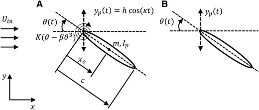
Fig. 1.
Schematic diagram depicting the flapping motion for A) AP–PP and B) AP–AP foils.
The generalized equation of motion for the passive pitching is as follows:
where θ indicates the instantaneous pitching rotation, defined clockwise positive; m is the mass and denotes the moment of inertia about the pivot point; C indicates structural damping coefficient. In order to account for the structural nonlinearities arising due to large pitch deflection, the torsional spring at the leading-edge was assumed to have cubic non-linearity; K and are the coefficient of linear and cubic stiffness terms, respectively. The stiffness model used here was motivated from the “click” mechanism of a Dipteran flight motor system (24). In Eq. 2, and are the location of pivot point and center of mass, respectively, measured from the leading-edge along the chord line. L and D are the lift and drag forces defined positive in direction of positive x and y axes, respectively.
Equations 1 and 2 are non-dimensionalised considering c and as the reference length and velocity scales, respectively, as follows:
Here, , , , , , , , and . The aerodynamic load coefficients, and , were computed at each time-step using the in-house flow solver (9) and then supplied to the structural solver to estimate the position of the foil in the next time-step. The structural and flow solvers exchange information in an explicit manner to simulate the coupled FSI dynamics, and a similar approach has been used in Ref. (25). The pitch response is computed by numerically integrating Eq. 4 using the fourth-order Runge–Kutta method, with initial conditions as and at . The present study focuses on very light weight wing configuration, and therefore, the solid to fluid density ratio, , was set to unity. The structural damping was assumed to be zero. The ratio of the coefficients of cubic and linear stiffness terms, β, was taken to be of high value () to ensure comparable contribution from the linear and cubic terms in Eq. 4. As a result, during the pitch oscillation, the linear stiffness dominated approximately for , and the cubic stiffness beyond that. The non-dimensional parameter values are summarized in Table 1. Hereafter the over-bar sign ( ) will be dropped from the symbols representing the non-dimensional parameters for the sake of typographical ease.
AP–AP
Under fully active situation (Fig. 1B), although the foil is allowed to oscillate in both plunge and pitch simultaneously, it is not free to oscillate passively, instead it is made to follow a set of pre-defined kinematics given by
where and are the mean pitch angle and the amplitude of pitch oscillation, respectively; is taken as in this study; ϕ indicates the phase-offset between the plunge and pitch motions. The plunge kinematics, location of the pitching pivot, and the frequency of flapping have been kept exactly the same as the AP–PP configuration. For pitching, a cosine function (Eq. 6) was assumed with the amplitude and phase-offset values taken from the outcome of the AP–PP simulations at respective values. This equivalence is maintained to enable a suitable comparison between the AP–PP and AP–AP cases.
Flow solver
A discrete forcing IBM-based in-house Navier–Stokes (N–S) solver (9) was employed to perform the flow simulations. In the chosen low Re regime, the flow-field around the flapping foil was assumed to be governed by the 2D incompressible N–S equations. The flow equations (Eqs. 7 and 8) were solved on a background Eulerian grid. Whereas, a set of Lagrangian markers were used to track the solid body location at every time-step, based on the solution of the structural solver. The presence of the flapping foil immersed inside the fluid was accounted by including a momentum forcing term, , to the momentum conservation equation (26). In the IBM framework, reconstructs the velocity values at the grid nodes inside the solid domain to satisfy the no-slip-no penetration boundary condition exactly on the solid boundary. A source/sink term, q, was added to the continuity equation to ensure mass conservation across the immersed boundary in a rigorous manner (26, 27). In the framework of discrete forcing IBM, the flow governing equations in the non-dimensional form are given by
where is non-dimensional flow velocity, and p denotes non-dimensional pressure. For more details, please refer to Refs. (9, 28, 29). Description of the computational domain, boundary conditions, grid size, and time-step size have been discussed in Section 1 of the supplementary material. Convergence and validation results in the context of the current problem are also presented in the supplementary material so as not to disturb the flow of reading here.
Dynamical behavior of AP–PP and AP–AP systems
It is well known from related literature that maximum non-dimensional plunge velocity, , is the key parameter to dictate the flow-field and its qualitative changes (1, 2, 5, 30, 31). The performance, dynamics, and the flow-field around the AP–PP foil were investigated considering as the bifurcation parameter here. We also evaluated the roles of the wing root stiffness (torsional spring stiffness) and the pitching pivot location on the dynamical behavior. Results for three typical values, , , and , will be discussed here, for a fixed κ of . Since the near-field behavior is directly reflected on the aerodynamic loads, the dynamical signatures were analyzed in terms of the phase portraits. The temporal values were normalized with the non-dimensional flapping period, , for the sake of presentation.
No aperiodic transition for the AP–PP configuration
The aerodynamic loads (for AP–PP foil) exhibited periodic signature across the range of . The evolution of trajectory repeated itself exactly in different flapping cycles, thus forming a perfect close-loop orbit on the phase portrait; see Fig. 2A–C. This is a strong characteristic of periodic dynamics and it establishes periodicity at as high as . In comparison, it exhibited a “quasi-periodic like” toroidal loop at high (Fig. 2F) for the equivalent AP–AP foil, although periodicity was retained at and (Fig. 2D and E). At , the trajectory was not perfectly repeatable, though the state variables stayed within its close neighborhood, forming a thick banded toroidal shaped portrait (Fig. 2F) indicating lack of periodicity. Please also refer to the supplementary Figs. S5–S8 (also Videos SV1 and SV2), for a comparison of the dynamical signatures.
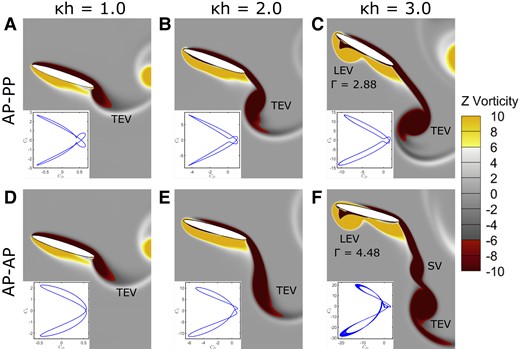
Fig. 2.
Near-field vorticity contours at a typical time instant of when the foil completed the upstroke and about to commence downstroke in a typical flapping cycle. Γ indicates the strength of LEV in terms of its circulation. SV, secondary vortex. Inset box in each of the frames represents the corresponding phase portrait. A–C) AP–PP and D–F) AP–AP foil at different values.
For actuated plunging, several studies (1, 2, 9, 13) reported the chaotic onset to occur around . Majumdar et al. (9), for a plunging configuration, reported quasi-periodicity around and chaos at . For actuated pitching–plunging, Bose et al. (4) also reported a similar range: a quasi-periodic flow-field at , appearance of intermittency at , and sustained chaos at ; note that the reporting of Bose et al. (4) was for zero phase difference between pitch and plunge motions, a non-zero phase-gap would have changed these onsets (10). On the other hand, as seen in the present results, aperiodic transition is completely absent (or delayed) due to passive pitch dynamics even at as high as ; see Fig. 2A–C and supplementary Video SV1.
Passive pitching was also seen to play a constructive role in aerodynamic load generation. At , took maximum and minimum values as and for the AP–AP foil (Fig. 2F) in a typical flapping cycle, resulting in net negative lift. Although these values were lower for the AP–PP foil ( and ; see Fig. 2C), it shows the net lift to be weakly positive. Moreover, at lower , where both the AP–AP and AP–PP foils generated lift symmetrically, AP–PP (; see Fig. 2A) produced approximately higher lift compared to the corresponding AP–AP (; see Fig. 2D) case.
It is known that aperiodic growth of strong LEVs and the subsequent vortex interactions are responsible for triggering aperiodicity/chaos in the flow-field (2, 5, 9). Present results revealed that these flow features, such as the LEVs, were either absent or very weak/attached to the body (no separation) for the AP–PP foil; see Fig. 2A–C. Even when the foil completed one stroke and started to commence the next, flow separation was conspicuously absent for all three , and no LEV shedding took place. Although weak LEVs were seen at high (see Fig. 2C), they remained attached to the body and could not undergo any interactions with the trailing-edge vortex (TEV). Hence, there were no obvious aperiodic agencies (such as aperiodic growth of LEVs and LEV–TEV interactions) present in the flow-field. A comparison of the flow-field between the AP–PP and AP–AP cases established this [near-fields looked very similar for and (Fig. 2), differences were noticeable for (Fig. 2C and F)]. The primary LEV for the AP–AP foil was also stronger (the circulation values should be noted in the figure), which approached the regime of aperiodicity (10). Furthermore, the shedding of a secondary vortex along with the main TEV contributed towards the loss of periodicity and influenced the aerodynamic loads; see supplementary Video SV2. This shows that the delay/inhibition of aperiodic transition can be attributed to the absence of separation of strong LEVs.
Passive motion optimally tunes the kinematics to delay aperiodic transition
The kinematics of passive pitch caused differences in the flow features between the active and the passive cases. The time evolution of the actuated plunge and passive pitch motions have been shown in Fig. 3. The amplitude of pitch increases with an increase in (, 35.11 and 41.22 for , 2.0, and 3.0, respectively), with pitch frequency being the same to that of plunge actuation. Clear phase-offsets between plunge and pitch motions were visible (Fig. 3), and the values increased with ; , 1.33, and for , 2.0 and , respectively. In the generic study of Majumdar et al. (10), considering a wide range of parameters for an actuated system, a significant delay in the aperiodic onset was reported in the range of . As given above, the phase-offsets for the current AP–PP foil fall within this range.
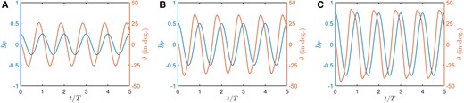
Fig. 3.
For AP–PP foil: time evolution of the plunge and pitch motions at A) , B) , and C) .
It is interesting to note that passive pitch is able to tune ϕ within the “safe” range of periodicity. Within this range, the leading-edge motion leads the trailing-edge, and helps the foil “slice through” the incoming free stream flow (see supplementary Video SV1 for a visualization of this gait) and maintain low effective angle-of-attack (AoA); see Fig. 4A. The effective AoA (), which is a measure of the relative orientation of the foil with respect to the incoming flow, can be estimated as (10)
has been evaluated with respect to the average downwash velocity induced by the entire chord, instead of downwash at any specific chord location. Derivation of Eq. 9 can be found in (10). In Fig. 4A, the maximum effective AoA () remained within a moderate level of even at high values for AP–PP. As a result, there were no major separation, and no obvious mechanism of aperiodicity in the near-field (Fig. 2A–C). For the equivalent AP–AP foil (Fig. 4B), took a much higher value, approximately , at . Note that can take values as high as even at at different ranges of ϕ for a fully actuated foil (10).
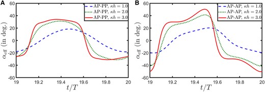
Fig. 4.
Variation in the effective AoA in a typical flapping cycle at three different for A) AP–PP and B) AP–AP configurations.
The difference in the dynamical behavior between the passive and the fully active systems can be justified by their respective pitch patterns as well; see Fig. 5 for a one-to-one comparison. The time history of θ and () phase portrait of AP–PP nominally resembled the sinusoidal patterns of the AP–AP at lower values, however, noticeable discrepancy was visible for . Especially the evolution looked quite different for . This explains the significant difference in the values between the two cases (Fig. 4), as can be justified by Eq. 9. Thus, intrinsic modification in the pitch pattern helps the passive case to maintain a lower effective AoA, which helps preventing aperiodic transitions, even though the main kinematic indicators are the same for both AP–PP and AP–AP cases. The passive pitch can influence the foil’s motion by two aspects. First, it takes the ϕ to the range of delayed aperiodic transition. Even though the aperiodic transition could be delayed in this regime, it is not entirely inhibited and may manifest for a pure sinusoidal kinematics at high (as happens for the current AP–AP case). Additionally, passive pitch adjusts the pitching pattern to avert aperiodic transition in comparison to a fully active case.
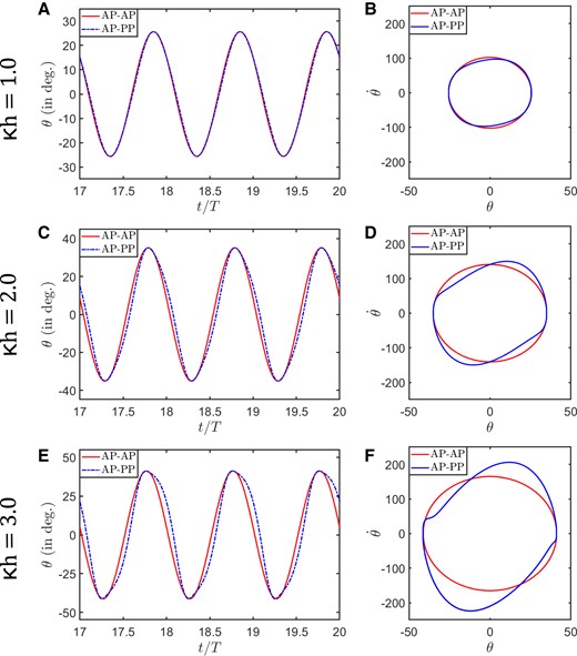
Fig. 5.
Time evolution of the pitch motion (A, C, E) and corresponding phase portraits (B, D, F) for the AP–PP and AP–AP foils at the three different .
Effect of variation in hinge stiffness
The torsional spring stiffness representing the wing root stiffness could be important in modulating the pitch movement of the passive system, in turn influencing the dynamical characteristics of the flow-field and loads. The stiffness of the torsional spring was varied systematically for this analysis by changing the value of K in Eq. 2, which reflects proportionately on the non-dimensional term . The simulations were performed for , , , and (), representing an increase in flexibility. The impact of the stiffness variation was analyzed for , which is susceptible to aperiodicity. At lower flexibility (when the behavior of the AP–PP foil is close to a rigid system), the load coefficients show deviation from periodicity (Fig. 6A). With increase in flexibility, the enhancement in the degree of free pitch takes the system back to periodicity (Fig. 6B and C). Stronger ability for passive movement enhances the foil’s capability to regularize itself with respect to the incoming flow, leading to attached and periodic flow-field. Note that periodic dynamics at higher flexibility does come at the cost of a reduction in load amplitudes, posing design challenges to balance the trade-off between the two.
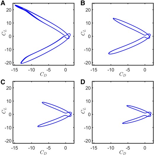
Fig. 6.
– phase portraits for the AP–PP foil as the flexibility along the pitch DOF increases at a fixed : A) , B) , C) , and D) .
Role of pivot location
Another crucial parameter that can influence the pitch dynamics of the passive system is the pivot location, which in turn can play a key role in controlling the dynamical behavior of the flow-field and loads. To evaluate the role of pivot location, we gradually moved the pivot location posteriorly from leading-edge such that , , , , and while the center of mass remained fixed at . The effect of the pivot location was studied for which was susceptible to aperiodic transition for the AP–AP situation. As the pivot location was varied gradually from the leading-edge towards trailing-edge, passive pitching was seen to have an adverse effect. When pivot was at the leading-edge (), passive pitch modulated the foil’s motion in such a way that the leading-edge led the trailing-edge and helped the foil to slice through the incoming flow maintaining a low effective AoA, and thus contributed towards delaying the aperiodic/chaotic transition. The corresponding – phase portrait displayed the perfect periodic signature (Figs. 2C, 6B, and 7A). On the contrary, as the pivot moved away from the leading-edge, the effective AoA increased and stronger LEVs were separated from the foil. As a result, the system displayed aperiodic signature (quasi-periodicity for and chaos for , and ; see Fig. 7B–E). This effect became the most prominent, when the pivot was at the trailing-edge; in this case the leading-edge lagged the trailing-edge, and as a result, the flapping foil created a significantly high effective AoA, resulting in the formation and separation of strong LEVs that triggered chaos. Overall, the ability of passive pitching to delay aperiodic/chaotic transition was highest when the pitching pivot was located at the leading-edge. As the pivot was moved towards trailing-edge, the passive pitch played an adverse role by advancing the chaotic transition.
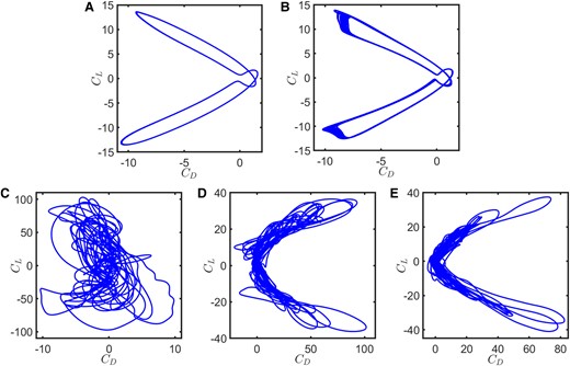
Fig. 7.
– phase portraits for the AP–PP foil as the pivot location changes at a fixed : A) , B) , C) , D) , and E) .
Effect of inflow fluctuations
In addition to aperiodicity, complexities like fluctuating/gusty inflows may also destabilize light weight (<100 g (32)) flapping wing systems with low flight speeds (<20 m/s (33)). Their low inertia makes them susceptible to irregular fluctuations/gust and have their aerodynamic performance affected (34, 35). Oncoming perturbations may potentially induce high instantaneous effective AoA leading to strongly separated flows (36, 37, 38), while the main agency of change for the near-field and the aerodynamic performance under gust comes through the LEV behavior (33, 38). It is also known that certain flapping kinematics can be useful in mitigating the detrimental effects of gust and in the recovery of aerodynamic loads (36, 37, 38). The potential of passive pitch to tune the kinematic patterns optimally for gust mitigation is immense. We will briefly examine its capability to attenuate the effect of irregular inflow fluctuations in this section. Please see Section 3 of the supplementary material for the mathematical details of a typical random (stochastic) temporally fluctuating inflow model (39).
Under inflow fluctuation, the overall temporal trends of loads (Fig. 8) remain similar to the respective steady inflow situations (see supplementary Figs. S5 and S7 for steady inflow results) but the time evolution shows modulations in amplitude. The fluctuations are most significant at the lowest (Fig. 8A and D) and decreases with an increase in (Fig. 8B and E). The signal-to-noise ratio (SNR), which measures the level of a desired signal in a time series data in comparison to the level of background noise and is defined as the ratio of signal power to the noise power (40), was tracked in Fig. 8F. For AP–AP, it increases from at to at ; for AP–PP from at to at . The noise power content in AP–PP decreased by nearly an order of magnitude compared to the fully active case (Fig. 8C). These results imply a much better gust mitigating capability of the AP–PP foil. Please see supplementary Videos SV3 and SV4 for flow visualization for both AP–PP and AP–AP cases under fluctuating inflows. Also note that while mitigating the effects of fluctuating inflow, passive pitching also leads to a reduction in the amplitudes. This can be understood by noting the approximate mean of the amplitudes in consecutive flapping cycles, as marked using black-dashed line in Fig. 8.
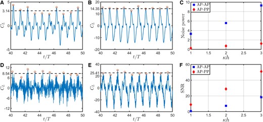
Fig. 8.
time history under stochastic inflow fluctuations for A) AP–PP foil at , B) AP–PP at , D) AP–AP foil at , and E) AP–AP foil at . C) Noise power content in the signals and F) SNR (signal power/noise power) at different values.
Discussions
Recently, we introduced two new non-dimensional quantities (10), and , which were shown to preserve a flapping system’s interaction with its surrounding flow comprehensively. It was further observed that the interactions could be effectively captured through the leading-edge excursion and the effective AoA. Both these non-dimensional quantities directly influence the LEV development, which is the main vortical mechanism responsible for triggering aperiodicity. Therefore, the fundamental aperiodic mechanisms can be effectively captured within these two non-dimensional measures. The definition of has been mentioned above; , the leading-edge amplitude-based Strouhal number, is defined as , with being the peak-to-peak oscillation amplitude of the leading-edge. The description allows one to combine the variation in relevant kinematic/flow parameters under these two quantities. The generalized aperiodic (bifurcation) boundaries on the vs. plane demarcates between the periodic and aperiodic dynamical regimes (10). For the AP–PP and AP–AP cases studied here, the corresponding (, ) pairs have been plotted on a dynamical transition map (Fig. 9) to further assess the changes due to passive dynamics. Bifurcation boundary and dynamical regions defined in Ref. (10) have also been reproduced here for reference. It can be seen that passive oscillations indeed keep the (, ) pair well within the periodic region of the map across different values. The trend observed for varying spring stiffness also supports the same: a decreasing stiffness moves the (, ) pair further inside the periodic regime and an increasing stiffness pushes it towards the transition boundary. On the other hand, for the AP–AP case at , the pair goes inside the aperiodic region (due to high effective AoA and high leading-edge oscillation speed), where comparatively stronger LEVs with aperiodic movements were formed. The associated deviation of the aerodynamic loads from periodicity was observed in the – phase portrait in Fig. 2F.
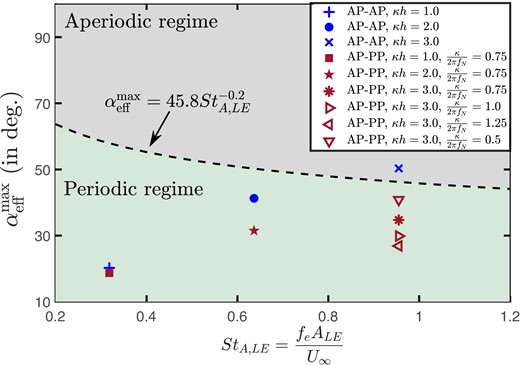
Fig. 9.
vs. values corresponding to the three for both AP–PP and AP–AP configurations.
Overall, the present study has been able to give some insights into the supposed inconsistency of the absence of chaos/aperiodicity in natural flights, despite the overwhelming presence of experimental (8, 7) and numerical evidence (1, 5, 9). Earlier studies reporting the presence of chaos have largely overlooked the significant role of passive oscillations, even though its influence on the kinematics was widely known (18, 19, 22, 23); furthermore, chordwise flexibility contributing to this effect was also reported (20, 21). As was seen in the present study, passive mechanisms, by tuning wing pitch kinematics, could achieve specific optimal orientations with respect to the incoming wind to avoid conditions conducive for aperiodic transitions.
Passive pitch dynamics also appears to provide better adjustment for overcoming realistic oncoming flows with unsteady fluctuations. Passive pitch modulates the foil’s orientation to adapt with the fluctuating inflow, thus reducing gust’s influence on aerodynamic loads. Fully actuated foils, on the other hand, experience significantly higher variations in its effective AoA due to a combination of self-motion and inflow fluctuations. Nevertheless, for both passive and fully active foils, an increase in helps to overcome the effects of fluctuations. This was also discussed in Ref. (36). Attenuation of the effects of gust results in a reduction in the aerodynamic load amplitudes, a similar trend was also reported in Ref. (41).
Conclusions
Effects of passive pitch dynamics on the characteristics of aerodynamic loads and near-field flow of flapping foils (with partial actuation) have been investigated in this study, in comparison to a fully actuated pitching and plunging foil. The flow-field and forces over the airfoil were computed at various dynamic plunge velocities. Aperiodic transition in the flow-field is significantly delayed/inhibited due to passive dynamics even at high amplitude–frequency kinematic ranges where aperiodic transition was observed in fully actuated foils. This is due to the passive modulation of the pitch kinematics that maintains a low effective AoA and results in the attenuation of LEV. The effects of changing wing root stiffness was also investigated which revealed that pitch modulation decreased with increasing stiffness resulting in increased likelihood for transition to aperiodicity. Passive pitch dynamics was most effective in averting chaotic transition when the pivot was at the leading-edge, and an adverse effect was seen as the pivot was moved towards trailing-edge. When subjected to unsteady inflow conditions, passive pitching also confers better gust mitigating ability because of the pitch profile adjusted to the local inflow. While passive oscillation can delay aperiodic transition and transition to chaos, and exhibit better gust mitigation, the overall forces experienced by the airfoil are lower, posing questions on the trade-off between load magnitudes and the periodic dynamics. The findings of the present work provide useful insights towards an efficient design for stable operations of futuristic flapping wing devices.
Supplementary Material
Supplementary material is available at PNAS Nexus online.
Authors’ Contributions
D.M., S.R., and S.S. conceptualized the research idea. D.M. conceived the code development, numerical simulations, and analyzed the results. D.M., S.R., and S.S. wrote and reviewed the manuscript.
Previous Presentation
These results have not been presented previously.
Data Availability
All data are included in the manuscript and/or supplementary material. The pre-processed data and associated codebase underlying this article are available at https://drive.google.com/drive/folders/1zQvPxzXj3lPz4Coc59wo2vjrzrCCBNTF
Funding
This work was funded by the Indian Institute of Technology Madras, India.
References
1
Ashraf
MA
,
Young
J
,
Lai
JCS
.
2012
.
Oscillation frequency and amplitude effects on plunging airfoil propulsion and flow periodicity
.
AIAA J
.
50
(
11
):
2308
–
2324
.
2
Badrinath
S
,
Bose
C
,
Sarkar
S
.
2017
.
Identifying the route to chaos in the flow past a flapping airfoil
.
Eur J Mech B Fluids
.
66
:
38
–
59
.
3
Blondeaux
P
,
Guglielmini
L
,
Triantafyllou
MS
.
2005
.
Chaotic flow generated by an oscillating foil
.
AIAA J
.
43
(
4
):
918
–
921
.
4
Bose
C
,
Gupta
S
,
Sarkar
S
.
2021
.
Dynamic interlinking between near-and far-field wakes behind a pitching–heaving airfoil
.
J Fluid Mech
.
911
:
A31
.
5
Bose
C
,
Sarkar
S
.
2018
.
Investigating chaotic wake dynamics past a flapping airfoil and the role of vortex interactions behind the chaotic transition
.
Phys Fluids
.
30
(
4
):
047101
.
6
Deng
J
,
Sun
L
,
Teng
L
,
Pan
D
,
Shao
X
.
2016
.
The correlation between wake transition and propulsive efficiency of a flapping foil: a numerical study
.
Phys Fluids
.
28
(
9
):
094101
.
7
Lentink
D
,
Van Heijst
GF
,
Muijres
FT
,
Van Leeuwen
JL
.
2010
.
Vortex interactions with flapping wings and fins can be unpredictable
.
Biol Lett
.
6
(
3
):
394
–
397
.
8
Lentink
D
,
Muijres
FT
,
Donker-Duyvis
FJ
,
van Leeuwen
JL
.
2008
.
Vortex-wake interactions of a flapping foil that models animal swimming and flight
.
J Exp Biol
.
211
(
2
):
267
–
273
.
9
Majumdar
D
,
Bose
C
,
Sarkar
S
.
2020
.
Capturing the dynamical transitions in the flow-field of a flapping foil using immersed boundary method
.
J Fluids Struct
.
95
:
102999
.
10
Majumdar
D
,
Bose
C
,
Sarkar
S
.
2022
.
Transition boundaries and an order-to-chaos map for the flow field past a flapping foil
.
J Fluid Mech
.
942
:
A40
.
11
Williams-Stuber
K
,
Gharib
M
.
1990
.
Transition from order to chaos in the wake of an airfoil
.
J Fluid Mech
.
213
:
29
–
57
.
12
Zaman
R
,
Young
J
,
Lai
JCS
.
2017
. .
13
Khalid
MSU
, et al.
2018
.
Bifurcations and route to chaos for flow over an oscillating airfoil
.
J Fluid Struct
.
80
:
262
–
274
.
14
Bøckmann
E
,
Steen
S
.
2014
.
Experiments with actively pitch-controlled and spring-loaded oscillating foils
.
Appl Ocean Res
.
48
:
227
–
235
.
15
Marais
C
,
Thiria
B
,
Wesfreid
JE
,
Godoy-Diana
R
.
2012
.
Stabilizing effect of flexibility in the wake of a flapping foil
.
J Fluid Mech
.
710
:
659
–
669
.
16
Shinde
SY
,
Arakeri
JH
.
2014
.
Flexibility in flapping foil suppresses meandering of induced jet in absence of free stream
.
J Fluid Mech
.
757
:
231
–
250
.
17
Shah
CL
,
Majumdar
D
,
Bose
C
,
Sarkar
S
.
2022
.
Chordwise flexible aft-tail suppresses jet-switching by reinstating wake periodicity in a flapping foil
.
J Fluid Mech
.
946
:
A12
.
18
Combes
SA
,
Daniel
TL
.
2003
.
Flexural stiffness in insect wings II. Spatial distribution and dynamic wing bending
.
J Exp Biol
.
206
(
17
):
2989
–
2997
.
19
Shyy
W
, et al.
2010
.
Recent progress in flapping wing aerodynamics and aeroelasticity
.
Prog Aerosp Sci
.
46
:
284
–
327
.
20
Zhao
L
,
Huang
Q
,
Deng
X
,
Sane
SP
.
2010
.
Aerodynamic effects of flexibility in flapping wings
.
J R Soc Interface
.
7
(
44
):
485
–
497
.
21
Bluman
JE
,
Sridhar
MK
,
Kang
C-K
.
2018
.
Chordwise wing flexibility may passively stabilize hovering insects
.
J R Soc Interface
.
15
(
147
):
20180409
.
22
Kang
C-K
,
Aono
H
,
Cesnik
CES
,
Shyy
W
.
2011
.
Effects of flexibility on the aerodynamic performance of flapping wings
.
J Fluid Mech
.
689
:
32
–
74
.
23
Shyy
W
,
Kang
C-K
,
Chirarattananon
P
,
Ravi
S
,
Liu
H
.
2016
.
Aerodynamics, sensing and control of insect-scale flapping-wing flight
.
Proc R Soc A: Math Phys Eng Sci
.
472
(
2186
):
20150712
.
24
Brennan
MJ
,
Elliott
SJ
,
Bonello
P
,
Vincent
JFV
.
2003
.
The “click” mechanism in dipteran flight: if it exists, then what effect does it have?
J Theor Biol
.
224
(
2
):
205
–
213
.
25
Griffith
MD
,
Jacono
DL
,
Sheridan
J
,
Leontini
JS
.
2016
.
Passive heaving of elliptical cylinders with active pitching—from cylinders towards flapping foils
.
J Fluids Struct
.
67
:
124
–
141
.
26
Kim
J
,
Kim
D
,
Choi
H
.
2001
.
An immersed-boundary finite-volume method for simulations of flow in complex geometries
.
J Comput Phys
.
171
(
1
):
132
–
150
.
27
Lee
J
,
Kim
J
,
Choi
H
,
Yang
K-S
.
2011
.
Sources of spurious force oscillations from an immersed boundary method for moving-body problems
.
J Comput Phys
.
230
(
7
):
2677
–
2695
.
28
Majumdar
D
,
Bose
C
,
Sarkar
S
.
2020
. .
29
Shah
CL
,
Majumdar
D
,
Sarkar
S
.
2019
. .
30
Lewin
GC
,
Haj-Hariri
H
.
2003
.
Modelling thrust generation of a two-dimensional heaving airfoil in a viscous flow
.
J Fluid Mech
.
492
:
339
–
362
.
31
Lai
JCS
,
Platzer
MF
.
1999
.
Jet characteristics of a plunging airfoil
.
AIAA J
.
37
(
12
):
1529
–
1537
.
32
Petricca
L
,
Ohlckers
P
,
Grinde
C
.
2011
.
Micro- and nano-air vehicles: state of the art
.
Int J Aerosp Eng
.
2011
:
214549
.
33
Lian
Y
,
Shyy
W
.
2007
.
Laminar-turbulent transition of a low Reynolds number rigid or flexible airfoil
.
AIAA J
.
45
(
7
):
1501
–
1513
.
34
Chirarattananon
P
, et al.
2017
.
Dynamics and flight control of a flapping-wing robotic insect in the presence of wind gusts
.
Interface Focus
.
7
(
1
):
20160080
.
35
Watkins
S
,
Milbank
J
,
Loxton
BJ
,
Melbourne
WH
.
2006
.
Atmospheric winds and their implications for microair vehicles
.
AIAA J
.
44
(
11
):
2591
–
2600
.
36
Fisher
A
, et al.
2016
.
The gust-mitigating potential of flapping wings
.
Bioinspir Biomim
.
11
(
4
):
046010
.
38
Viswanath
K
,
Tafti
DK
.
2010
.
Effect of frontal gusts on forward flapping flight
.
AIAA J
.
48
(
9
):
2049
–
2062
.
39
Majumdar
D
,
Bose
C
,
Sarkar
S
.
2020
.
Effect of gusty inflow on the jet-switching characteristics of a plunging foil
.
Phys Fluids
.
32
(
11
):
117105
.
40
Rajasekar
S
,
Sanjuan
MAF
.
2016
,
Nonlinear resonances
.
Switzerland: Springer International Publishing
.
Author notes
© The Author(s) 2023. Published by Oxford University Press on behalf of National Academy of Sciences.
This is an Open Access article distributed under the terms of the Creative Commons Attribution-NonCommercial-NoDerivs licence (
https://creativecommons.org/licenses/by-nc-nd/4.0/), which permits non-commercial reproduction and distribution of the work, in any medium, provided the original work is not altered or transformed in any way, and that the work is properly cited. For commercial re-use, please contact journals.permissions@oup.com


