-
PDF
- Split View
-
Views
-
Cite
Cite
Masaki Iwasawa, Daisuke Namekata, Keigo Nitadori, Kentaro Nomura, Long Wang, Miyuki Tsubouchi, Junichiro Makino, Accelerated FDPS: Algorithms to use accelerators with FDPS, Publications of the Astronomical Society of Japan, Volume 72, Issue 1, February 2020, 13, https://doi.org/10.1093/pasj/psz133
Close - Share Icon Share
Abstract
We describe algorithms implemented in FDPS (Framework for Developing Particle Simulators) to make efficient use of accelerator hardware such as GPGPUs (general-purpose computing on graphics processing units). We have developed FDPS to make it possible for researchers to develop their own high-performance parallel particle-based simulation programs without spending large amounts of time on parallelization and performance tuning. FDPS provides a high-performance implementation of parallel algorithms for particle-based simulations in a “generic” form, so that researchers can define their own particle data structure and interparticle interaction functions. FDPS compiled with user-supplied data types and interaction functions provides all the necessary functions for parallelization, and researchers can thus write their programs as though they are writing simple non-parallel code. It has previously been possible to use accelerators with FDPS by writing an interaction function that uses the accelerator. However, the efficiency was limited by the latency and bandwidth of communication between the CPU and the accelerator, and also by the mismatch between the available degree of parallelism of the interaction function and that of the hardware parallelism. We have modified the interface of the user-provided interaction functions so that accelerators are more efficiently used. We also implemented new techniques which reduce the amount of work on the CPU side and the amount of communication between CPU and accelerators. We have measured the performance of N-body simulations on a system with an NVIDIA Volta GPGPU using FDPS and the achieved performance is around 27% of the theoretical peak limit. We have constructed a detailed performance model, and found that the current implementation can achieve good performance on systems with much smaller memory and communication bandwidth. Thus, our implementation will be applicable to future generations of accelerator system.
1 Introduction
In this paper we describe new algorithms implemented in FDPS (Framework for Developing Particle Simulators: Iwasawa et al. 2016; Namekata et al. 2018), to make efficient use of accelerators such as GPGPUs (general-purpose computing on graphics processing units). FDPS is designed to make it easy for researchers to develop their own programs for particle-based simulations. To develop efficient parallel programs for particle-based simulations requires a very large amount of work, comparable with the work of a large team of people for many years. This is of course true not only for particle-based simulations, but for any large-scale parallel applications in computational science. The main cause of this problem is that modern high-performance computing (HPC) platforms have become very complex, requiring a lot of effort to develop complex programs to make efficient use of such platforms.
Typical modern HPC systems are actually a cluster of computing nodes connected through a network, each with typically one or two processor chips. The largest systems at present consist of around 105 nodes, and we will see even larger systems soon. This extremely large number of nodes has made the design of the inter-node network very difficult, and the design of parallel algorithms has also become much harder. The calculation times of the nodes must be accurately balanced. The time necessary for communication must be small enough that the use of large systems is meaningful. The communication bandwidth between nodes is much lower than the main memory bandwidth, which itself is very small compared to the calculation speed of CPUs. Thus, it is crucial to avoid communications as much as possible. The calculation time can show an increase, instead of decreasing as it should, when we use a large number of nodes, unless we are careful to achieve good load balance between nodes and to minimize communication.
In addition, the programming environments available on present-day parallel systems are not easy to use. What is most widely used is MPI (Message-Passing Interface), which requires one to write explicitly how each node communicates with others in the system. Just to write and debug such a program is difficult, and it has become nearly impossible for any single person or even for a small group of people to develop large-scale simulation programs which run efficiently on modern HPC systems.
Moreover, this extremely large number of nodes is just one of the many difficulties of using modern HPC systems, since even within one node there are many levels of parallelism to be taken care of by the programmer. To make matters even more complicated, these multiple levels of parallelism are interwoven with multiple levels of memory hierarchy with varying bandwidth and latency. For example, the supercomputer Fugaku, which is under development in Japan at the time of writing, will have 48 CPUs (cores) in one chip. These 48 cores are divided into four groups, each with 12 cores. Cores in one group share one level-2 cache memory. The cache memories in different groups communicate with each other through a cache coherency protocol. Thus, the access of one core to the data which happens to be in its level-2 cache is fast, but that in the cache of another group can be very slow. Also, access to the main memory is much slower, and that to local level-1 cache is much faster. Thus, we need to take into account the number of cores and the size and speed of caches at each level to achieve acceptable performance. To make matters even worse, many modern microprocessors have level-3 and even level-4 caches.
As a result of these difficulties, only a small number of researchers (or groups of researchers) can develop their own simulation programs. In the case of cosmological and galactic N-body and smoothed particle hydrodynamics (SPH) simulations, Gadget (Springel 2005) and pkdgrav (Stadel 2001) are the most widely used. For star cluster simulations, NBODY6++ and NBODY6++GPU (Nitadori & Aarseth 2012) are effectively the standard. For planetary ring dynamics, REBOUND (Rein & Liu 2012) has been available. There has been no public code for simulations of the planetary formation process until recently.
This situation is clearly unhealthy. In many cases the physics that needs to be modeled is quite simple: particles interact through gravity, and with some other interactions such as physical collisions. Even so, almost all researchers are now forced to use existing programs developed by someone else, simply because HPC platforms have become too difficult to use. To add new functionality to existing programs can be very difficult. In order to make it possible for researchers to develop their own parallel code for particle-based simulations, we have developed FDPS (Iwasawa et al. 2016).
The basic idea of FDPS is to separate the code for parallelization and that for interaction calculation and numerical integration. FDPS provides the library functions necessary for parallelization, and using them researchers write programs very similar to what they would write for a single CPU. Parallelization on multiple nodes and on multiple cores in a single node are taken care of by FDPS.
FDPS provides three sets of functions. One is for domain decomposition. Given the data of particles in each node, FDPS performs the decomposition of the computational domain. The decomposed domains are assigned to MPI processes. The second set of functions is to let MPI processes exchange particles. Each particle should be sent to the appropriate MPI process. The third set of functions perform the interaction calculation. FDPS uses a parallel version of the Barnes–Hut algorithm for both long-range interactions such as gravitational interactions and short-range interactions such as intermolecular force or fluid interaction. The application program supplies the function to perform interaction calculations for two groups of particles (one group exerting forces on the other), and FDPS calculates the interaction using that function.
FDPS offers very good performance on large-scale parallel systems consisting of “homogeneous” multi-core processors, such as the K computer and Cray systems based on x86 processors. On the other hand, the architecture of large-scale HPC systems is moving from homogeneous multi-core processors to accelerator-based systems and heterogeneous multi-core processors.
GPGPUs are the most widely used accelerators, and are available on many large-scale systems. They offer price–performance ratios and performance per watt numbers significantly better than those of homogeneous systems, primarily by integrating a large number of relatively simple processors on a single accelerator chip. On the other hand, accelerator-based systems have two problems. One is that, for many applications, the communication bandwidth between CPUs and accelerators becomes the bottleneck. The second is that because CPUs and accelerators have separate memory spaces, the programming is complicated and we cannot use existing programs.
Though in general it is difficult to use accelerators, for particle-based simulations the efficient use of accelerators is not so difficult, and that is why the GRAPE families of accelerators specialized for gravitational N-body simulations have been successful (Makino et al. 2003). GPGPUs are also widely used both for collisional (Gaburov et al. 2009) and collisionless (Bédorf et al. 2012) gravitational N-body simulations. Thus, it is clearly desirable for FDPS to support accelerator-based architectures.
Though gravitational N-body simulation programs have achieved very good performance on large clusters of GPGPUs, achieving high efficiency for particle systems with short-range interactions is difficult. For example, there exist many high-performance implementations of SPH algorithms on a single GPGPU, or on a relatively small number of multiple GPGPUs (around six), but there are not many high-performance SPH programs for large-scale parallel GPGPU systems. Practically all the efficient GPGPU implementations of the SPH algorithm use GPGPUs to run the entire simulation code, in order to eliminate the communication overhead between GPGPU and CPU. The calculation cost of particle–particle interactions dominates the total calculation cost of SPH simulations. Thus, as far as the calculation cost is concerned, it is sufficient to let GPGPUs evaluate the interactions, and let CPUs perform the rest of the calculation. However, because of the relatively low communication bandwidth between CPUs and GPGPUs we need to avoid data transfer between them, and if we let GPGPUs do all the calculations it is clear that we can minimize the communication.
On the other hand, it is more difficult to develop programs for GPGPUs than for CPUs, and to develop MPI parallel programs for multiple GPGPUs is clearly even more difficult. To make such an MPI parallel program for GPGPUs run on a large cluster is close to impossible.
In order to add support for GPGPUs and other accelerators to FDPS, we decided to take a different approach. We kept the simple model in which accelerators do the interaction calculation only, and CPUs do all the rest. However, we try to minimize the communication between CPUs and accelerators as much as possible, without making the calculation on the accelerator side very complicated.
In this paper we describe our strategy of using accelerators, how application programmers can use FDPS to efficiently use accelerators, and the performance achieved. The paper is organized as follows: In section 2 we present an overview of FDPS. In section 3 we discuss the traditional approach of using accelerators for interaction calculation, and its limitations. In section 4 we summarize our new approach. In section 5 we show how users can use new APIs of FDPS to make use of accelerators. In section 6 we give the results of performance measurement for GPGPU-based systems, along with a performance prediction for hypothetical systems. Section 7 provides a summary and discussion.
2 Overview of FDPS
The basic idea (or the ultimate goal) of FDPS is to make it possible for researchers to develop their own high-performance, highly parallel particle-based simulation programs without spending too much time writing, debugging, and performance tuning the code. In order to achieve this goal, we have designed FDPS so that it provides all necessary functions for efficient parallel programming of particle-based simulations. FDPS uses MPI for inter-node parallelization and OpenMP for intra-node parallelization. In order to reduce the communication between computing nodes, the computational domain is divided using the recursive multisection algorithm (Makino 2004), but with weights for particles to achieve optimal load balancing (Ishiyama et al. 2009). The number of subdomains is equal to the number of MPI processes, and one subdomain is assigned to one MPI process.
Initially, particles are distributed to MPI processes in an arbitrary way. It is not necessary that the initial distribution is based on spatial decomposition, and it is even possible that initially just one process has all the particles, if it has sufficient memory. After the spatial coordinates of subdomains are determined, for each particle, the MPI process to which it belongs is determined, and it is sent to that process; this can all be achieved just by calling FDPS library functions. In order for the FDPS functions to get information on particles and copy or move them, they need to know the data structure of the particles. This is made possible by making FDPS “template based,” so that at compile time the FDPS library functions know the data structure of the particles.
After the particles are moved to their new locations, the interaction calculation is done through the parallel Barnes–Hut algorithm based on the local essential tree (Makino 2004). In this method, each MPI process first constructs a tree structure from its local particles (local tree). Then, it sends to all other MPI processes the information necessary for that MPI process to evaluate the interaction with its particles. This necessary information is called the local essential tree (LET).
After one process has received all the LETs from all other nodes, it constructs the global tree by merging the LETs. In FDPS, merging is not actually done but LETs are first reduced to arrays of particles and superparticles (hereafter called “SPJ”), and a new tree is constructed from the combined list of all particles. Here, an SPJ represents a node of the Barnes–Hut tree.
Finally, the interaction calculation is done by traversing the tree for each particle. Using Barnes’ vectorization algorithm (Barnes 1990), we traverse the tree for a group of local particles and create the “interaction list” for that group. Then, FDPS calculates the interaction exerted by particles and superparticles in this interaction list on particles in the group, by calling the user-supplied interaction function.
In the case of long-range interaction we use the standard Barnes–Hut scheme for treewalk. In the case of short-range interaction such as SPH interaction between particles, we still use treewalk but with the cell-opening criterion different from the standard opening angle.
Thus, users of FDPS can use the functions for domain decomposition, particle migration, and interaction calculation by passing their own particle data class and interaction calculation function to FDPS at compile time. The interaction calculation function should be designed as receiving two arrays of particles, one exerting the “force” on the other.
3 Traditional approach to using accelerators and its limitation
As we have already stated in the introduction, accelerators have been used for gravitational N-body simulations, both on single and parallel machines, with and without Barnes–Hut treecode (Barnes & Hut 1986). In the case of the tree algorithm, the idea is to use Barnes’ vectorization algorithm, which is what we defined as the interface between the user-defined interaction function and FDPS. Thus, in principle we can use accelerators just by replacing the user-defined interaction function with one that uses the accelerators. In the case of GRAPE processors, that would be the only thing we need to do. At the same time, this would be the only thing we can do.
On modern GPGPUs, however, we need to modify the interface and algorithm slightly. There are two main reasons for this modification. The first is that the software overhead of GPGPUs for data transfer and kernel startup is much larger than for GRAPE processors. Another difference is in the architecture. GRAPE processors consist of a relatively small number of highly pipelined, application-specific pipeline processors for interaction calculation, with hardware support for the fast summation of results from multiple pipelines. On the other hand, GPGPUs consist of a very large number of programmable processors, with no hardware support for summation of the results obtained on multiple processors. Thus, to make efficient use of GPGPUs we need to calculate interactions on a large number of particles by a single call to the GPGPU computing kernel. The vectorization algorithm has one adjustable parameter, ngrp, the number of particles which share one interaction list, and it is possible to make efficient use of GPGPUs by making ngrp large. However, using an excessively large ngrp causes an increase in the total calculation cost, and is thus not desirable.
Hamada et al. (2009) introduced an efficient way to use GPGPUs that they called the “multiwalk” method. In their method, the CPU first constructs multiple interaction lists for multiple groups of particles, and then sends them to the GPGPU in a single kernel call. The GPGPU performs the calculations for multiple interaction lists in parallel, and returns all the results in a single data transfer. In this way we can tolerate the large overhead of invoking computing kernels on GPGPUs and the lack of support for fast summation.
Even though this multiwalk method is quite effective, there is still room for improvement, meaning that on modern accelerators the efficiency we can achieve with the multiwalk method is rather limited.
The biggest remaining inefficiency comes from the fact that with the multiwalk method we send interaction lists for each particle group. One interaction list is an array of physical quantities (at least positions and masses) of particles. Typically, the number of particles in an interaction list is ∼10 times more than the number of particles for which that interaction list is constructed, and thus the transfer time of the interaction list is around 10 times longer than that of the particles which receive the force. This means that we are sending the same particles (and superparticles) multiple times when we send multiple interaction lists.
In the next section we discuss how we can reduce the amount of communication and also further reduce the calculation cost for the parts other than the force calculation kernel.
4 New algorithms
As described in the previous section, to send all the particles in the interaction list to accelerators is inefficient because we send the same particles and SPJs multiple times. In subsection 4.1 we will describe new algorithms to overcome this inefficiency. In subsection 4.2 we will also describe new algorithms to further reduce the calculation cost for the parts other than the force calculation kernel. In subsection 4.3 we will describe the actual procedures with and without the new algorithms.
4.1 Indirect addressing of particles
When we use the interaction list method on systems with accelerators, in the simplest implementation, for each group of particles and its interaction list, we send the physical quantities necessary for interaction calculation, such as positions and masses in the case of gravitational force calculation. Roughly speaking, the number of particles in the interaction list is around ten times longer than that in one group. Thus, we are sending around 10n particles, where n is the number of particles per MPI process, at each timestep. Since there are only n local particles and the number of particles and tree nodes in an LET is generally much smaller than n, this means that we are sending the same data many times, and that we should be able to reduce the communication by sending particle and tree node data only once. Some GRAPE processors, including GRAPE-2A, MDGRAPE-x, and GRAPE-8, have hardware support for this indirect addressing (Makino & Daisaka 2012).
In the case of programmable accelerators, this indirect addressing can be achieved by first sending arrays of particles and tree nodes, and then sending the interaction list (here the indices of particles and tree nodes indicating their location in the arrays). The user-defined interaction calculation function should be modified so that it uses indirect addressing to access particles. Examples of such code are included in the current FDPS distribution (version 4.0 and later), and we plan to develop template routines which can be used to generate code on multiple platforms from user-supplied code for the interaction calculation.
The interaction list is usually an array of 32-bit integers (four bytes), and one item of particle data is at least 16 bytes (when positions and masses are all in single precision numbers), but can be much larger in the case of SPH and other methods. Thus, with this method we can reduce the communication cost by a large factor.
One limitation of this indirect addressing method is that all the particles in one process should fit in the memory of the accelerator. Most accelerators have relatively small memories. In such cases we can still use this method, by dividing the particles into blocks small enough to fit the accelerator memory. For each block, we construct the “global” tree structure similar to that for all particles in the process, and interaction lists for all groups under the block.
4.2 Reuse of interaction Lists
For both long-range and short-range interactions, FDPS constructs the interaction lists for groups of particles. It is possible to keep using the same interaction lists for multiple timesteps if particles do not move large distances in a single timestep. In the case of SPH or molecular dynamics simulations, it is guaranteed that particles move only a small fraction of the interparticle distance in a single timestep, since the size of the timestep is limited by the stability condition. Thus, in such cases we can safely use the interaction lists for several timesteps.
Even in the case of gravitational many-body simulations, there are cases where the change of the relative distance between particles in a single timestep is small. For example, in simulations of planetary formation processes or planetary rings, the random velocities of particles are very small, and thus, even though particles move large distances, there is no need to reconstruct the tree structure at each timestep because the changes in the relative positions of particles are small.
In the case of galaxy formation simulation using the Nbody+SPH technique, generally the timestep for the SPH part is much smaller than that for the gravity part, and thus we should be able to use the same tree structure and interaction lists for multiple SPH steps.
If we use this algorithm (hereafter we call it the reuse algorithm), the procedures for interaction calculation for the step with and without tree construction are different. The procedure for the tree construction step is:
Construct the local tree.
Construct the LET for all other processes. These LETs should be list of indices of particles and tree nodes, so that they can be used later.
Exchange LETs. Here, the physical information for tree nodes and particles should be exchanged.
Construct the global tree.
Construct the interaction lists.
Perform the interaction calculation for each group using the constructed list.
The procedure for reusing steps is:
Update the physical information of the local tree.
Exchange LETs.
Update the physical information of the global tree.
Perform the interaction calculation for each group using the constructed list.
In many cases we can keep using the same interaction list for around 10 timesteps. In the case of planetary ring simulation, using the same list for a much larger number of timesteps is possible, because the stepsize of planetary ring simulation using the “soft-sphere” method (Iwasawa et al. 2018) is limited by the hardness of the “soft” particles and is thus much smaller than the usual timescale determined by the local velocity dispersion and interparticle distance.
With this reuse algorithm, we can reduce the cost of the following steps: (a) tree construction, (b) LET construction, and (c) interaction list construction. The calculation costs of steps (a) and (c) are O(N) and O(Nlog N), respectively. Thus they are rather large for simulations with a large number of particles. Moreover, by reducing the cost of step (c), we can make the group size ngrp small, which results in a decrease of the calculation cost due to the use of the interaction list. Thus, the overall improvement in efficiency is quite significant.
The construction and maintenance of interaction lists and other necessary data structures are all done within FDPS. Therefore, user-developed application programs can use this reuse algorithm just by calling the FDPS interaction calculation function with one additional argument indicating reuse/construction. The necessary change for an application program is very small.
4.3 Procedures with or without the new algorithms
In this section we describe the actual procedures of simulations using FDPS with or without the new algorithms. Before describing the procedures, let us introduce the four particle data types FDPS uses: FP (Full Particle), EPI (Essential Particle I), EPJ (Essential Particle J), and FORCE. FP is the data structure containing all the information on a a particle, EPI (J) is used for the minimal data of particles that receive (give) the force, and the FORCE type stores the calculated interaction. FDPS uses these additional three data types to minimize memory access during the interaction calculation. We first describe the procedure for the calculation without the reuse algorithm and then describe that for the reuse algorithm.
At the beginning of one timestep, the computational domains assigned to MPI processes are determined and all processes exchange particles so that all particles belong to their appropriate domains. Then, the coordinates of the root cell of the tree are determined using the positions of all particles. After the determination of the root cell, each MPI process constructs its local tree. The local tree construction consists of the following four steps:
Generate Morton keys for all particles.
Sort key–index pairs in Morton order by radix sort.
Reorder FPs in Morton order referencing the key–index pairs and copy the particle data from FPs to EPIs and EPJs.
For each level of the tree, from top to bottom, allocate tree cells and link their child cells. In each level we use binary search to find the cell boundaries.
In the case of the reusing step, these steps are skipped.
After the construction of the local tree, multipole moments of all local tree cells are calculated, from the bottom to the top of the tree. The calculation of the multipole moments is performed even at the reusing step, because the physical quantities of particles are updated at each timestep.
After the calculation of the multipole moments of the local tree, each MPI process constructs LETs and sends them to other MPI processes. When the reusing algorithms is used, at the tree construction step each MPI process saves the LETs and their destination processes.
After the exchange of LETs, each MPI process constructs the global tree from received LETs and its local tree. The procedure is almost the same as that for the local tree construction.
After the construction of the global tree, each MPI process calculates the multipole moments of all cells of the global tree. The procedure is the same as that for the local tree.
After the calculation of the moments of the global tree, each MPI process constructs the interaction lists and uses them to perform the force calculation. If we do not use the multiwalk method, each MPI process makes the interaction lists for one particle group and then the user-defined force kernel calculates the forces from EPJs and SPJs in the interaction list on the EPIs in the particle group.
When we use the multiwalk method, each MPI process makes multiple interaction lists for multiple particle groups. When the indirect addressing method is not used, each MPI process gives multiple groups and multiple interaction lists to the interaction kernel on the accelerator. Thus we can summarize the force calculation procedure without the indirect addressing method for multiple particle groups as follows:
Construct the interaction list for multiple particle groups.
Copy EPIs and the interaction lists to the send buffer for the accelerator. Here, the interaction list consists of EPJs and SPJs.
Send particle groups and their interaction lists to the accelerator.
Let the accelerator calculate interactions on the particle groups sent at step 3.
Receive the results calculated at step 4 and copy them back to the FPs, integrate the orbits of FPs, and copy the data from FPs to EPIs and EPJs.
To calculate the forces on all particles, the above steps are repeated until all particle groups are processed. Note that the construction of the interaction list (step 1), sending the data to the accelerator (step 3), the actual calculation (step 4), and receiving the calculated result (step 5) can all be overlapped.
On the other hand, when the indirect addressing method is used, before the construction of the interaction lists, each MPI process sends the data of all cells of the global tree to the accelerator. Thus, at the beginning of the interaction calculation it should send them to the accelerator. After that, the accelerator receives the data of particle groups and their interaction lists, but here the interaction list contains the indices of EPJs and SPJs and not their physical quantities. Thus, the calculation procedure with the indirect addressing method is the same as that without indirect addressing except that all the global tree data are sent at the beginning of the calculation and the interaction lists sent during the calculation contain only indices of tree cells and EPJs.
We can use the reusing method both with and without the indirect addressing method. For the construction step, the procedures are the same. For the reusing steps, we can skip the steps for constructing the interaction list (step 1). When we use the indirect addressing method, we can also skip sending them since the lists of indices are unchanged during reuse.
5 APIs for using accelerators
In this section we describe the APIs (application programming interfaces) of FDPS for using accelerators and how to use them by showing sample code developed for NVIDIA GPGPUs. Part of the user kernel is written in CUDA.
FDPS has high-level APIs to perform all the procedures for interaction calculation in a single API call. For the multiwalk method, FDPS provides calcForceAllAndWriteBackMultiWalk or calcForceAllAndWriteBackMultiWalkIndex. The difference between these two functions is that the former dose not use the indirect addressing method. These two API functions can be used to replace calcForceAllAndWriteBack, which is another top-level function provided by FDPS distribution version 1.0 or later. A user must provide two force kernels: the “dispatch” and “retrieve” kernels. The “dispatch” kernel is used to send EPIs, EPJs, and SPJs to accelerators and call the force kernel. The “retrieve” kernel is used to collect FORCEs from accelerators. The reason FDPS needs two kernels is to allow overlap of the calculation on the CPU with the force calculation on the accelerator as described in the previous section.
The reusing method can be used with all three top-level API calls described above. The only thing users do to use the reusing method is to give an appropriate FDPS-provided enumerated type value to these functions so that the reusing method is enabled. The values FDPS provides are MAKE_LIST, MAKE_LIST_FOR_REUSE, and REUSE_LIST. At the construction step the application program should pass MAKE_LIST_FOR_REUSE to the top-level API function so that FDPS constructs the trees and the interaction lists and saves them. At the reusing step, the application program should pass REUSE_LIST so that FDPS skips the construction of the trees and reuses the interaction lists constructed at the last construction step. In the case of MAKE_LIST, FDPS also constructs the trees and the interaction lists but does not save them. Thus the users cannot use the reusing method. Figure 1 shows an example of how to use the reusing method. Here, the trees and the interaction lists are constructed once every eight steps. While the same list is being reused, particles should remain in the same MPI process as at the time of list construction. Thus, exchangeParticle should be called only just before the tree construction step.
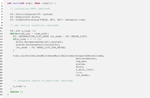
Figure 2 shows an example of the dispatch kernel without the indirect addressing method. FDPS gives the dispatch kernel the arrays of pointers to the EPIs, EPJs, and SPJs as arguments of the kernel (lines 3, 5, and 7). Each pointer points to the address of the first element of the arrays of EPIs, EPJs, and SPJs for one group and its interaction list. The sizes of these arrays are given by |${\rm n\_epi}$| (line 4), |${\rm n\_epj}$| (line 6) and |${\rm n\_spj}$| (line 8). FDPS also passes “tag” (the first argument) and “n_walk” (the second argument). The argument “tag” is used to specify individual accelerators if multiple accelerators are available. However, in the current version of FDPS, “tag” is disabled and FDPS always passes 0. The argument “n_walk” is the number of particle groups and interaction lists.
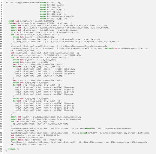
Example of the dispatch kernel without the indirect addressing method. (Color online)
To overlap the actual force calculation on the GPGPU with the data transfer between the GPGPU and the CPU we use a CUDA stream, which is a sequence of operations executed on the GPGPU. In this example we used N_STREAM CUDA streams. In this paper we used eight CUDA streams because the performance of our simulations does not improve even if we use more. In each stream, |${\rm n\_walk / N\_STREAM}$| interaction lists are handled. The particle data types, EPIs (lines 28–33), EPJs (lines 36–41), and SPJs (lines 48–48), are copied to the send buffers for GPGPUs. Here, we use the same buffer for EPJs and SPJs because the EPJ and SPJ types are the same. In lines 55 and 56, the EPIs and EPJs are sent to the GPGPU. Then the force kernel is called in line 60.
Figure 3 shows an example of the dispatch kernel with the indirect addressing method. This kernel is almost the same as that without the indirect addressing method except for two differences. One difference is that at the beginning of one timestep, all data of the global tree (EPJs and SPJs) are sent to the GPGPU (lines 15 and 16). Whether or not the application program sends EPJs and SPJs to the GPGPU is specified by the 13th argument, “send_flag.” If “send_flag” is true, the application program sends all EPJs and SPJs. Another difference is that indices of EPJs and SPJs are sent (lines 48–58 and 67–69) instead of the physical quantities of EPJs and SPJs. Here, we use the user-defined global variable CONSTRUCTION_STEP to specify whether the current step is a construction or reusing step. At the construction step CONSTRUCTION_STEP becomes unity and the user program sends the interaction list to the GPGPU and saves them in the GPGPU. On the other hand, at the reusing step, the user program does not send the list and reuses the interaction list saved in the GPGPU.
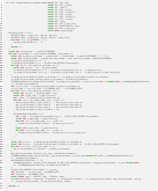
Example of the dispatch kernel with the indirect addressing method. The boxes with a solid line indicate the differences from the kernel without the indirect addressing method. (Color online)
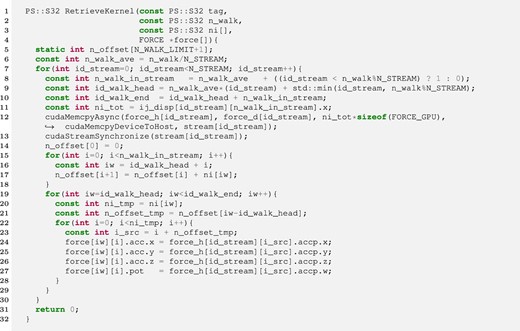
Figure 4 shows an example of the retrieve kernel. The same retrieve kernel can be used with and without the indirect addressing method. In line 12, the GPGPU sends the interaction results to the receive buffer of the host (D2H copy). To let the CPU wait until all functions in the same stream on the GPGPU are completed, cudaStreamSynchronize is called in line 13. Finally, the interaction results are copied to FORCEs. Note that this retrieve kernel could be optimized by launching all D2H copies at once and then processing stream 1 once it is finished, while D2H copies for other streams are still in flight. However, in most particle simulations the execution time for the force calculation is much longer than that for D2H copies. Thus we think that using this optimized kernel would not change the performance.
6 Performance
In this section we present the measured performance and the performance model of a simple N-body simulation code implemented using FDPS on CPU-only and CPU + GPGPU systems.
6.1 Measured performance
To measure the performance of FDPS, we performed simple gravitational N-body simulations both with and without the accelerator. The initial model is a cold uniform sphere. This system will collapse in a self-similar way. Thus we can use the reusing method. The number of particles (per process) n is 222 (4M). The opening criterion of the tree, θ, is between 0.25 and 1.0, the maximum number of particles in a leaf cell is 16, and the maximum number of particles in the EPI group, ngrp, is between 64 and 16384. We performed these simulations with three different methods, listed in table 1. In the case of the reusing method, the number of reusing steps between the construction steps nreuse is between 2 and 16. For all simulations we used a monopole-only kernel.
| Method . | System . | Multiwalk . | Indirect addressing . | Reusing . |
|---|---|---|---|---|
| C1 | CPU | No | No | No |
| G1 | CPU + GPGPU | Yes | No | No |
| G2 | CPU + GPGPU | Yes | Yes | No |
| G3 | CPU + GPGPU | Yes | Yes | Yes |
| Method . | System . | Multiwalk . | Indirect addressing . | Reusing . |
|---|---|---|---|---|
| C1 | CPU | No | No | No |
| G1 | CPU + GPGPU | Yes | No | No |
| G2 | CPU + GPGPU | Yes | Yes | No |
| G3 | CPU + GPGPU | Yes | Yes | Yes |
| Method . | System . | Multiwalk . | Indirect addressing . | Reusing . |
|---|---|---|---|---|
| C1 | CPU | No | No | No |
| G1 | CPU + GPGPU | Yes | No | No |
| G2 | CPU + GPGPU | Yes | Yes | No |
| G3 | CPU + GPGPU | Yes | Yes | Yes |
| Method . | System . | Multiwalk . | Indirect addressing . | Reusing . |
|---|---|---|---|---|
| C1 | CPU | No | No | No |
| G1 | CPU + GPGPU | Yes | No | No |
| G2 | CPU + GPGPU | Yes | Yes | No |
| G3 | CPU + GPGPU | Yes | Yes | Yes |
We used an NVIDIA TITAN V as an accelerator. Its peak performance is 13.8 Tflops for single precision calculation. The host CPU is a single Intel Xeon E5-2670 v3 with a peak speed of 883 Gflops for single precision calculation. The GPGPU is connected to the host CPU through a PCI Express 3.0 bus with 16 lanes. The main memory of the host computer is DDR4-2133. The theoretical peak bandwidth is 68 GB s−1 for the host main memory and 15.75 GB s−1 for the data transfer between the host and GPGPU. All particle data is double precision. The force calculation on the GPGPU and the data transfer between the CPU and GPGPU are performed in single precision.
Figure 5 shows the average elapsed time per step for methods C1, G1, G2, and G3 with reuse intervals nreuse of 2, 4, and 16 plotted against the average number of particles which share one interaction list 〈ni〉. We also plot the elapsed times for method G3 for the reusing step (i.e., this corresponds to the time with nreuse = ∞). The opening angle is θ = 0.5.
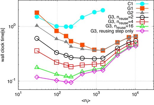
Averaged elapsed time per step against 〈ni〉, in the case of θ = 0.5 and n = 222. Open symbols indicate the results of the runs with method G3. Open squares, open upward triangles, and open inverted triangles indicate the results with nreuse of 2, 4, and 16, respectively. Open circles and open diamonds indicate the elapsed times of the construction step and the reusing step, respectively. Filled circles and filled squares indicate the elapsed times for methods C1 and G1, respectively. (Color online)
We can see that in the case of method G3, the elapsed time becomes smaller as the reuse interval nreuse increases, and approaches the time of the reusing step. The minimum time of method G3 at the reusing step is ten times smaller than method C1 and four times smaller than method G1. The performance of method G3 with nreuse of 16 is 3.7 Tflops (27% of the theoretical peak).
We can also see that the optimal value of 〈ni〉 becomes smaller as nreuse increases. When we do not use the reuse method, the tree construction and traversal are done at every step. Thus, their costs are large, and to make it small we should increase 〈ni〉. In order to do so, we need to use large ncrit, which is the maximum number of particles in the particle group. If we make 〈ni〉 too large, the calculation cost increases (Makino 1991). Thus there is an optimal 〈ni〉. When we use the reuse method, the relative cost of tree traversal becomes smaller. Thus, the optimal 〈ni〉 becomes smaller and the calculation cost also becomes smaller. We will give a more detailed analysis in subsection 6.2.
Table 2 shows the breakdown of the calculation time for different methods in the case of θ = 0.5. For the runs with C1 and G1, we show the breakdown at the optimal values of 〈ni〉, which are 230 and 1500, respectively. For the runs with G2 and G3 at the reusing step, we show the breakdowns for 〈ni〉 = 230. We can see that the calculation time for G3 at the reusing step is four times smaller than for G2. Thus, if nreuse ≫ 4, the contribution of the construction step to the total calculation time is small.
Breakdown of the total time per step for the runs with various methods in the case of θ = 0.5 and n = 222.*
| Method . | C1 . | G1 . | G2 . | G3 (reusing step) . |
|---|---|---|---|---|
| 〈ni〉 | 230 | 1500 | 230 | 230 |
| Set root cell | 0.0064 | 0.0066 | 0.0066 | — |
| Make local tree | 0.091 | 0.092 | 0.095 | — |
| Calculate key | 0.0084 | 0.0085 | 0.0093 | — |
| Sort key | 0.042 | 0.043 | 0.044 | — |
| Reorder ptcl | 0.030 | 0.030 | 0.030 | — |
| Link tree cell | 0.011 | 0.010 | 0.011 | — |
| Calculate multipole moment of local tree | 0.0053 | 0.0058 | 0.0053 | 0.0062 |
| Make global tree | 0.094 | 0.094 | 0.096 | 0.0071 |
| Calculate key | 0.0 | 0.0 | 0.0 | — |
| Sort key | 0.040 | 0.041 | 0.042 | — |
| Reorder ptcl | 0.036 | 0.036 | 0.037 | 0.0071 |
| Link tree cell | 0.011 | 0.011 | 0.011 | — |
| Calculate multipole moment of global tree | 0.0066 | 0.0064 | 0.0065 | 0.0068 |
| Calculate force | 0.76 | 0.15 | 0.21 | 0.072 |
| Make interaction list (EPJ and SPJ) | (0.16) | 0.063 | — | — |
| Make interaction list (id) | — | — | 0.13 | — |
| Copy all particles and tree cells | — | — | (0.0065) | (0.0065) |
| Copy EPI | — | (0.0037) | (0.0037) | (0.0037) |
| Copy interaction list (EPJ and SPJ) | — | (0.020) | — | — |
| Copy interaction list (id) | — | — | (0.013) | — |
| Copy FORCES | — | (0.0060) | (0.0060) | (0.0060) |
| Force kernel | (0.43) | (0.11) | (0.043) | (0.043) |
| H2D all particles and tree cells | — | — | (0.0073) | (0.0073) |
| H2D EPI | — | (0.0042) | (0.0042) | (0.0042) |
| H2D interaction list (EPJ and SPJ) | — | (0.034) | — | — |
| H2D interaction list (id) | — | — | (0.022) | — |
| D2H FORCE | — | (0.0067) | (0.0067) | (0.0067) |
| Write back + integration (+ copy ptcl) | 0.015 | 0.016 | 0.021 | 0.025 |
| Total | 0.98 | 0.36 | 0.42 | 0.095 |
*The second row shows the 〈ni〉 used in this measurement. The times in parentheses are the estimated times using the performance model discussed in the following sections, because the calculations corresponding to these times are hidden by other calculations and we cannot measure them.
Figure 6 shows the average elapsed time at optimal 〈ni〉 plotted against θ for methods C1, G1, G2, and G3 with nreuse of 2, 4, and 16. We also plot the elapsed times for the reusing step of method G3. The slope for method C1 is steeper than for the other methods. This is because the time for the force kernel dominates the total time in the case of method C1 and it strongly depends on θ.
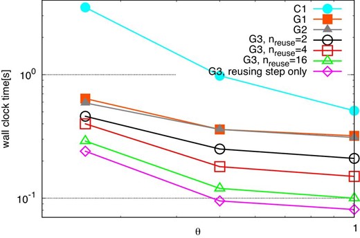
Total times for various methods at the optimal 〈ni〉 against θ, in the case of n = 222. The symbols are as in figure 5. (Color online)
6.2 Performance model on a single node
6.2.1 Model of Troot
| Symbol . | Value . | Explanation . |
|---|---|---|
| αconst list | 19 | Slowdown factor for constructing the interaction list. |
| αcp all | 0.87 | Slowdown factor for copying EPJs and SPJs to the send buffer. |
| αcp EPI | 1.0 | Slowdown factor for copying EPIs to the send buffer. |
| αcp FORCE | 1.2 | Slowdown factor for copying FORCEs from the receive buffer. |
| αcp list | 1.0 | Slowdown factor for copying the interaction lists to the send buffer. |
| αD2H FORCE | 1.2 | Slowdown factor for sending FORCEs from the GPGPU to the host. |
| αdc sort | 7.7 | Slowdown factor for determining domains. |
| α(all)gather | 0.62 | Slowdown factor for MPI_(All)gather. |
| αGPU calc | 1.7 | Slowdown factor for calculating interactions on the GPGPU. |
| αGPU transfer | 2.7 | Slowdown factor for sending EPJs from the main memory of the GPGPU. |
| αH2D all | 1.0 | Slowdown factor for sending EPJs and SPJs from host to GPGPU. |
| αH2D EPI | 1.0 | Slowdown factor for sending EPIs from host to GPGPU. |
| αH2D list | 0.86 | Slowdown factor for sending the interaction lists from host to GPGPU. |
| αkey | 0.85 | Slowdown factor for constructing the key–index pairs. |
| αlink | 3.4 | Slowdown factor for linking tree cells. |
| αmom | 1.8 | Slowdown factor for calculating multipole moments of tree cells. |
| αp2p | 1.0 | Slowdown factor for communicating neighboring nodes. |
| αreorder lt | 1.1 | Slowdown factor for reordering particles for the local tree. |
| |$\alpha ^{\rm const}_{\rm reorder\, gt}$| | 5.0 | Slowdown factor for reordering particles for the global tree at the construction step. |
| |$\alpha ^{\rm reuse}_{\rm reorder\, gt}$| | 1.0 | Slowdown factor for reordering particles for the global tree at the reuse step. |
| αroot | 0.70 | Slowdown factor for searching the root cell. |
| αsort | 1.1 | Slowdown factor for sorting the key–index pairs. |
| αwb+int+cp | 1.4 | Slowdown factor for writing back FORCEs, integrating orbits, and copying variables |
| from FP to EPI and EPJ. | ||
| b EPI | 24 bytes | Size of an EPI. |
| b EPI buf | 12 bytes | Size of an EPI in the receive buffer. |
| b EPJ | 32 bytes | Size of an EPJ. |
| b EPJ buf | 16 bytes | Size of an EPJ in the receive buffer. |
| b FORCE | 32 bytes | Size of a FORCE. |
| b FORCE buf | 16 bytes | Size of a FORCE in the receive buffer. |
| b FP | 88 bytes | Size of an FP. |
| b index | 4 bytes | Size of an array index for EPJ and SPJ. |
| b ID | 4 bytes | Size of an interaction list index for EPJ and SPJ. |
| b ID buf | 4 bytes | Size of a receive buffer index for EPJ and SPJ. |
| b key | 16 bytes | Size of a key–index pair. |
| b pos | 24 bytes | Size of the position of an FP. |
| n op | 23 | The number of operations per interaction. |
| τ(all)gather, startup | 1.2 × 10⁻⁵ s | Start-up time for MPI_(All)gather of the K computer. |
| τp2p,startup | 1.0 × 10⁻⁵ s | Start-up time for communicating with neighboring nodes of the K computer. |
6.2.2 Model of Tconstlt
The reason why αlink lt is much larger than unity is that in the binary search the address to access depends on the data just read.
6.2.3 Model of Tmom lt
6.2.4 Model of Tconst gt
6.2.5 Model of Treorder gt
In table 3 we can see that |$\alpha ^{\rm reuse}_{\rm reorder\, gt}$| is much smaller than |$\alpha ^{\rm const}_{\rm reorder\, gt}$| because we use the array indices for EPJ and SPJ saved at the construction step to reorder the particles.
6.2.6 Model of Tmom gt
6.2.7 Models of Tforce,const and Tforce,reuse
In table 3 we can see that αconst list and αGPU transfer are much larger than unity because random access of the main memory is slow for both the host and the GPGPU.
6.2.8 Model of Tstep,const and Tstep,reuse
In order to check whether the model we constructed is reasonable or not, in figure 7 we compare the times predicted by equations (31) and (32) with the measured times on the systems which consist of an Intel Xeon E5-2670 v3 and NVIDIA TITAN V (left panel), and an Intel Core i9-9820x and NVIDIA RTX2080 (right panel). We can see that the predicted times agree very well with the measured times on both systems.
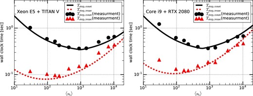
Total elapsed time for both the construction and reusing steps on systems consisting of an Intel Xeon E5-2670 v3 and NVIDIA TITAN V (left panel) and an Intel Core i9-9820x and NVIDIA RTX2080 (right panel). The solid (dashed) curve and filled circles (triangles) indicate respectively the predicted time by using the model and the measured time, in the case of the construction (reusing) step. (Color online)
In the following, we analyze the performance of the N-body simulations on hypothetical systems with various Bhost, Btransfer, FGPU, and BGPU by using the performance model. Unless otherwise noted, we assume a hypothetical system with Bhost = 100 GB s−1, Btransfer = 10 GB s−1, BGPU = 500 GB s−1, and FGPU = 10 Tflops as a reference system. This reference system can be regarded as a modern HPC system with a high-end accelerator.
Figure 8 shows the calculation time per timestep on the reference system for 4M particles and θ = 0.5 for nreuse = 1, 4, and 16. We can see that the difference in the performance for nreuse = 4 and nreuse = 16 is relatively small. In the rest of the section we use nreuse = 16 and θ = 0.5.
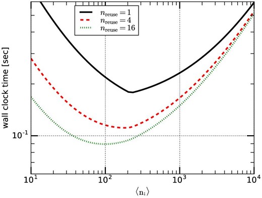
Calculation time per timestep on the reference system for various nreuse. (Color online)
We consider four different types of hypothetical systems: GPU2X, GPU4X, LINK4X, and LINK0.5X. Their parameters are listed in table 4. Figure 9 shows the calculation times per timestep for the four hypothetical systems. We can see that increasing the bandwidth between CPU and accelerator (LINK4X) has a relatively small effect on the performance. On the other hand, increasing the overall accelerator performance has a fairly large impact.
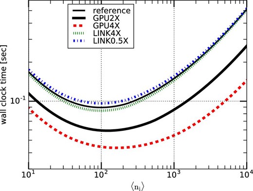
Mean execution time per step, Tstep single, on various hypothetical systems against 〈ni〉. (Color online)
| System . | F GPU . | B host . | B GPU . | B transfer . |
|---|---|---|---|---|
| Reference | 10 Tflops | 100 GB s−1 | 500 GB s−1 | 10 GB s−1 |
| GPU2X | 20 Tflops | 100 GB s−1 | 1 TB s−1 | 10 GB s−1 |
| GPU4X | 40 Tflops | 100 GB s−1 | 2 TB s−1 | 10 GB s−1 |
| LINK4X | 10 Tflops | 100 GB s−1 | 500 GB s−1 | 40 GB s−1 |
| LINK0.5X | 10 Tflops | 100 GB s−1 | 500 GB s−1 | 5 GB s−1 |
Figure 10 shows the relative execution time of hypothetical systems in the two-dimensional plane of Bhost and Btransfer. The contours indicate the execution time relative to the reference system. In other words, systems on the contour with a value of X are X times slower than the reference system.
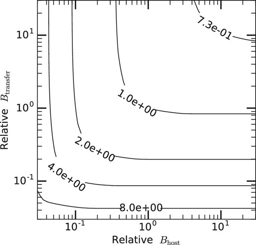
Relative execution time of hypothetical systems in the two-dimensional plane of relative Bhost and relative Btransfer. The contours indicate the execution time relative to the reference system. The values of the contours and the x- and y-axes are normalized by those of the reference system.
We can see that an increase of Bhost or Btransfer, or even both, would not give significant performance improvement, while an increase of the accelerator performance gives a significant speedup. Even when both Bhost and Btransfer are reduced by a factor of ten, the overall speed is reduced by a factor of four. Thus, if the speed of accelerator is improved by a factor of ten, the overall speedup is four. We can therefore conclude that the current implementation of FDPS can provide good performance not only on the current generation of GPGPUs but also for future generations of GPGPUs or other accelerator-based systems, which will have relatively poor data transfer bandwidth compared to their calculation performance.
6.3 Performance model on multiple nodes
In this section we discuss the performance model of the parallelized N-body simulation with method G3. Here, we assume the network is the same as that of the K computer. Detailed communication algorithms are given in Iwasawa et al. (2016).
In the original implementation of FDPS, MPI_Alltoallv was used for the exchange of LETs and it was the main bottleneck in the performance for large np (Iwasawa et al. 2016). Thus, we recently developed a new algorithm for the exchange of LETs to avoid the use of MPI_Alltoallv (Iwasawa et al. 2018). The new algorithm is as follows:
Each process sends the multipole moment of the top-level cell of its local tree to all processes using MPI_Allgather.
Each process calculates the distances from all other domains.
If the distance between processes i and j is large enough that process i can be regarded as one cell from process j, that domain already has the necessary information. If not, process i constructs a LET for process j and sends it to process j.
Figure 11 shows the weak-scaling performance for N-body simulations in the case of the number of particles per process n = 220. Here we assume that nreuse = ndc = 16, nsmp = 30, 〈ni〉 = 250, and θ = 0.5. We can see that Tstep,para is almost constant for np ≲ 105. For np ≳ 105, Tstep,para slightly increases because TLET,allgather becomes large. Roughly speaking, when n is much larger than np the parallel efficiency is high.
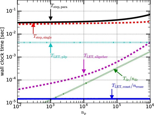
Weak-scaling calculation time plotted as a function of np. The number of particles per node is 220. (Color online)
Figure 12 shows the strong-scaling performance in the case of the total number of particles N = 230 (left panel) and N = 240 (right panel). In the case of N = 240, Tstep,para scales well up to np = 106. On the other hand, in the case of N = 230, for nP ≳ 3000 the slope of Tstep,para becomes shallower because TLET,p2p becomes relatively large. For nP ≳ 50000, Tstep,para increases because TLET,allgather becomes relatively large. We can also see that Tstep,single increases linearly with np for np ≳ 105. This is because Tstep,single depends on nLET, which is proportional to np for large np. Thus, to improve the scalability further we need to reduce TLET,allgather and TLET,p2p. We will discuss ideas for reducing them in subsections 7.1 and 7.2.
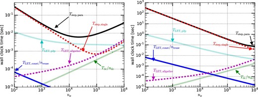
Strong-scaling calculation time plotted as a function of np. The left and right panels show the results in the cases of the total number of particles N of 230 and 240, respectively. (Color online)
7 Discussion and summary
7.1 Further reduction of communication
For simulations on multiple nodes, the communication of the LETs with neighboring nodes (TLET,p2p) becomes a bottleneck for very large np. Thus, it is important to reduce the data size for this communication.
An obvious way to reduce the amount of data transfer is to apply some data compression techniques. For example, the physical coordinates of neighboring particles are similar, and thus there is clear room for compression. However, for many particle-based simulations, compression in the time domain might be more effective. In the time domain we can make use of the fact that the trajectories of most particles are smooth, so we can construct fitting polynomials from several previous timesteps. When we send the data of one particle at a new timestep, we send only the difference between the prediction from the fitting polynomial and the actual value. Since this difference is many orders of magnitude smaller than the absolute value of the coordinate itself, we should be able to use a much shorter word format for the same accuracy. We probably need some clever way to use a variable-length word format. We can apply compression in the time domain not only for coordinates but for any physical quantities of particles, including the calculated interactions such as gravitational potential and acceleration. We can also apply the same compression technique to communication between the CPU and the accelerator.
7.2 Tree of domains
As we have seen in figure 12, for large np the total elapsed time increases linearly with np because the elapsed times for the exchange of LETs and the construction of the global tree are proportional to np if np is very large. To remove this linear dependency on np we can introduce a tree structure to the computational domains (tree of domains) (Iwasawa et al. 2018). By using the tree of domains and exchanging the locally combined multipole moments between distant nodes, we can remove MPI_Allgather among all processes to exchange LETs. This means that the times for the exchange of LETs and the construction of the global tree do not increase linearly with np.
7.3 Further improvement in single-node performance
Considering the trends in HPC systems, the overall performance of the accelerator (FGPU and BGPU) increases faster than the bandwidths of the host main memory (Bhost) and the data bus between the host and the accelerator (Btransfer). Therefore, in the near future the main performance bottleneck could be Bhost and Btransfer.
The amount of data copied in the host main memory and data transfer between the host and the accelerator for the reusing step are summarized in tables 5 and 6. We can see that the amounts of data copied and transfered are about 15n and 3n. One reason for the large amount of data access is that there are four different particle data types (FP, EPI, EPJ, and FORCE) and data are copied between different data types. If we use only one particle data type we could avoid data copying in procedures (e) and (g) in table 5 and procedure (B) in table 6. If we do so, the amount of data copying in the main memory and data transfer between host and accelerator could be reduced by 40% and 33%, respectively.
Amount of particle data copied in the host main memory for the specified procedures (left column).
| Procedure . | Amount of data . |
|---|---|
| (a) Calculate multipole moments of local tree | n |
| (b) Reorder particles for global tree | 3n |
| (c) Calculate multipole moments of global tree | n |
| (d) Copy EPJ and SPJ to the send buffer | 2n |
| (e) Copy EPI to the send buffer | 2n |
| (f) Copy FORCE from the receive buffer | 2n |
| (g) Write back FORCEs to FPs, integrate orbits of FPs, and copy FPs to EPIs and EPJs | 4n |
Amount of particle data transfer between host and accelerator for the specified procedures (left column).
| Procedure . | Amount of data . |
|---|---|
| (A) Send EPJ and SPJ | n |
| (B) Send EPI | n |
| (C) Receive FORCE | n |
| Procedure . | Amount of data . |
|---|---|
| (A) Send EPJ and SPJ | n |
| (B) Send EPI | n |
| (C) Receive FORCE | n |
Another way to improve the performance is to implement all procedures on the accelerator, because the bandwidth of the device memory (BGPU) is much faster than Bhost and Btransfer. In this case, the performance would be determined by the overall performance of the accelerator.
7.4 Summary
In this paper we have described the algorithms we implemented in FDPS to allow efficient and easy use of accelerators. Our algorithm is based on Barnes’ vectorization, which has been used both on general-purpose computers (and thus previous versions of FDPS) and on GRAPE special-purpose processors and GPGPUs. However, we have minimized the amount of communication between the CPU and the accelerator by an indirect addressing method, and we further reduce the amount of calculation on the CPU side by interaction list reusing. The performance improvement over the simple method based on Barnes’ vectorization on the CPU can be as large as a factor of ten on the current generation of accelerator hardware. We can also expect a fairly large performance improvement on future hardware, even if the relative communication performance is expected to degrade.
The version of FDPS described in this paper is available at 〈https://github.com/FDPS/FDPS〉.
Acknowledgements
We are indebted to an anonymous referee for valuable comments. Numerical computations were in part carried out on the K computer at RIKEN Center for Computational Science through the HPCI System Research project (Project ID:ra000008) and on the Cray XC50 at the Center for Computational Astrophysics, National Astronomical Observatory of Japan. Part of the research covered in this paper was funded by MEXT’s program for the Development and Improvement for the Next Generation Ultra High-Speed Computer System, under its Subsidies for Operating the Specific Advanced Large Research Facilities. M.I. is supported by JSPS KAKENHI Grant Numbers JP18K11334 and JP18H04596.
Appendix 1. Performance model of force kernel on GPGPU
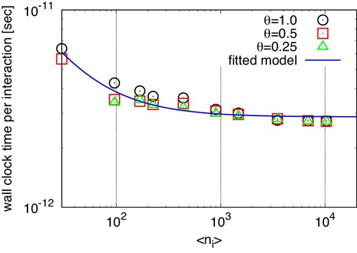
Elapsed time for interaction calculations per interaction. The circles, squares, and triangles indicate the results for θ = 1.0, 0.5, and 0.25, respectively. The solid curve indicates the fitted model. (Color online)
To determine the coefficients for equation (A1), we assume that FGPU is 13.8 Tflops and BGPU is about 550 GB s−1, which is measured with bandwidthTest in the NVIDIA SDK. These coefficients are listed in table 3.
Appendix 2. Performance of MPI_Gather and MPI_Allgather on the K Computer
Here, we construct performance models of MPI_Gather and MPI_Allgather on the K computer. On this computer the performance of MPI_Gather is almost the same as that of MPI_Allgather. Thus, in the following we only consider MPI_Allgather.
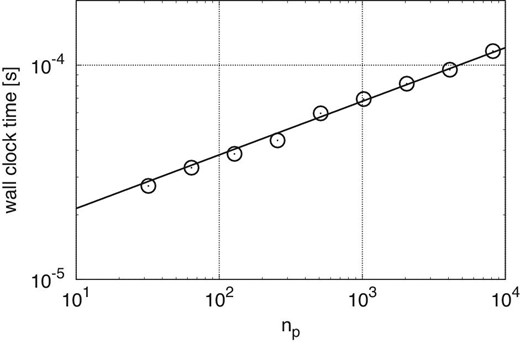
Elapsed time for MPI_Allgather to send a two-byte message against the number of processes. The circles indicate the measurement values and the solid curve indicates our fitting model.
Figure 15 shows the measured and predicted times for MPI_Allgather against the message size. Here, we assume Binj = 4.8 GB s−1 from the results of a point-to-point communication test. The parameters in equation (A5) are listed in table 3. Our model agrees reasonably well with the measured data. Note that we can see a disconnect between b = 100 and 1000. We think that this disconnect is caused by a change in algorithm of the MPI library.
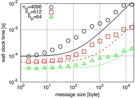
Elapsed times for MPI_Allgather plotted against the message size. The circle, square, and triangle indicate the results with np = 4096, 512, and 64, respectively. The solid, dashed, and dotted curves indicate our fitting models for np = 4096, 512, and 64, respectively.
References


