


Abstract
Electrochemical energy storage has been an important enabling technology for modern electronics of all kinds, and will grow in importance as more electric vehicles and grid-scale storage systems are deployed. We briefly review the history of intercalation electrodes and basic concepts pertaining to batteries based on intercalation reactions. Then we summarize how the critical performance metrics—energy density, power density, safety and stability—relate back to electrode materials properties, and how these materials properties are related to fundamental chemical and physical structure relationships highlighted with the most recent research advancement. Challenges and avenues for further research have been highlighted throughout.
INTRODUCTION
The need for energy storage
Energy storage—primarily in the form of rechargeable batteries—is the bottleneck that limits technologies at all scales. From biomedical implants [1] and portable electronics [2] to electric vehicles [3–5] and grid-scale storage of renewables [6–8], battery storage is the primary cost and design limitation. Batteries already play an important supporting role in modern life. On one hand, we can look to recent history. The release of the iPhone in 2007, among other key drivers, enabled the sweeping technological and cultural shifts that we are witnessing today. But this is only made feasible with decades’ worth of advances in rechargeable battery technology (and even still we bump up against frustratingly short battery life!).
At the same time, we can also look forward and see how future battery advances and economies of scale will help scrub CO2 emissions from transportation and the grid. Economical energy storage lets battery-powered electric vehicles replace internal combustion engines in the transportation sector, which now accounts for the plurality of CO2 emissions in the USA (∼34% through March 2016) [9]. High-profile hybrid and fully electric vehicles like the Toyota Prius, Tesla Model S, Nissan Leaf and Chevrolet Volt have catalysed this trend away from gasoline. Even in spite of concerns about coal-powering these electric vehicles [10,11], better batteries will in fact compound the environmental benefits as storage helps renewables supplant coal and other fossil-fuel power plants [12,13].
For grid-scale applications, the benefits of adding storage are many and well documented [14,15]. Beyond increased penetration of intermittent renewable generation, batteries’ fast response times (seconds) and relatively long discharge time (hours) make them viable for applications across many time scales [16]. Storage helps with frequency regulation, which balances generation and load in real-time and increases grid reliability [17]. On the scale of minutes and hours, storage also supplies previously stored power during times of high demand (load leveling) and mitigates the need for additional installed capacity on the grid (peak shaving). Over the long term, reducing the load allows utilities to avoid the cost of new substations and transmission lines (T&D deferral) [18]. Not all applications are mutually compatible [14], but they can still be combined to match the needs of different actors and locations [19–22] and fundamentally transform the grid.
Here, C is the total cost of the storage system, including both capital and operating costs, per unit mass (or volume), E is the energy density per unit mass (or volume) of the device at the pack level, n is the lifetime of the battery measured in cycles and η is the roundtrip energy efficiency. This formula clarifies the main goals of battery scientists and engineers. Cost is minimized with design choices that favor abundant materials and scalable processing techniques. Energy density increases with higher-voltage and -capacity materials, and more efficient cell architectures. Incident-free long life is achieved with materials that are mechanically, thermally and electrochemically stable, and added by battery-management systems. The overall energy efficiency is determined by both the behavior of the redox-active material and the power electronics of the battery pack itself. Optimizing these variables simultaneously (without compromising safety) is the herculean challenge for the battery community [29].
Historical context for intercalation chemistry
While a full history of intercalation is well beyond the scope of this review, it is worth briefly surveying the foundation on which the Li-ion battery was built. Similarly to today, the initial push for rechargeable battery technology was driven by fossil-fuel anxieties and growing demands on electronics [30]. Urban smog, diminishing oil reserves and geopolitics spurred interest in oil alternatives in the early 1970s [31]. After the discovery of β-alumina [32] and the development of solid-state ionics [33], researchers recognized the potential for batteries based on intercalation. By 1976, Whittingham and others at Exxon produced the first lithium battery, which used layered TiS2 as the cathode and Li metal as the anode [34]. The battery provided ∼480 mWh/g when discharged at a rate of 10 mA, but fundamental safety and manufacturing problems prevented its widespread adoption.
For better or worse, the 1980s brought more efficient vehicles, new oil reserves and cutbacks to alternative-energy research in the wake of global recession [31]. All of these conspired against significant battery research and development. Even so, the seminal advances of Goodenough's LiCoO2 cathode [35] and Yazami's graphite anode [36] eventually paved the way for the first commercial Li-ion batteries. The first LiCoO2/carbonaceous battery was later assembled by Yoshino at Asahi Kasei Corporation [37]. The propylene carbonate non-aqueous electrolyte allowed for high-voltage operation (∼3.6 V), graphite resolved the safety issues associated with lithium metal anodes, and LiCoO2 was a sufficiently stable and robust material for manufacturing and long-term cycling. Sony enabled the wireless revolution when they commercialized this technology in 1991 [38].
Despite tremendous effort and investment at the lever of research and development [39], most battery progress has been made at the manufacturing level, not because of materials advances. For Li-ion batteries, only five practical cathode materials and two anode materials have been commercialized to date (Table 1) [40–47].
Rechargeable Li-ion battery intercalation electrode materials.
| Average | Practical | Date | ||||
|---|---|---|---|---|---|---|
| Material | Structure | voltage | capacity | first | Reference | |
| (V vs. Li) | (mAh/g) | reported | ||||
| LiCoO2 | Layered | ∼3.9 | ∼140 | 1980 | 35 | |
| LiMn2O4 | Spinel | ∼4.1 | ∼120 | 1983 | 43 | |
| Cathodes | LiFePO4 | Olivine | ∼3.45 | ∼160 | 1997 | 44 |
| LiNi1/3Mn1/3Co1/3O2 | Layered | ∼3.8 | ∼200 | 2001 | 45 | |
| LiNi0.8Co0.15Al0.05O2 | Layered | ∼3.8 | ∼200 | 2003 | 46 | |
| Anodes | Graphite (LiC6) | Layered | ∼0.1 | ∼360 | 1983 | 36 |
| Li4Ti5O12 | Spinel | ∼1.5 | ∼175 | 1994 | 47 |
Adapted from [40–42].
There is a strong empirical understanding of how to improve performance and economics (e.g. by using thinner separators, thicker electrodes and proprietary protocols for solid–electrolyte interface formation), but even today there are many fundamental mysteries about what exactly is happening within a battery. The rich scientific challenges (and ample funding) of electrochemical energy storage have led to the rapid growth of worldwide research activity, and many exciting new chemistries are under development. Today, lead–acid and Li-ion batteries are the major rechargeable battery chemistries. Other rechargeable technologies based on nickel–metal hydride and nickel–cadmium chemistries are being phased out. However, the persistence of technologies that are over 150 years old (lead–acid and primary alkaline batteries) shows how difficult the challenge is. Nevertheless, new battery configurations including redox flow batteries [48–51], sodium-ion batteries [52–54], multivalent (e.g. Mg2+, Al3+) batteries [55–57], metal–sulfur batteries [58,59], metal–air batteries [60–62], pseudocapacitors [63], metal chloride batteries [64,65] and other schemes [66,67] have been demonstrated—both in the lab and in the field [54,68,69].
This wide array of battery materials converts energy only via a few mechanisms. Alloying reactions take place with metal anodes like Si or Sn [70–72]. Conversion reactions take place at the cathode of air batteries and metal fluorides, as well as certain oxide and sulfide anode materials (e.g. Fe3O4 and MoS2) [73]. These mechanisms allow for very high capacities, but large volume changes and minimal long-term reversibility, among other issues, have hindered their practical application. This review focuses on the third mechanism: intercalation. Intercalation is the process by which a mobile ion or molecule is reversibly incorporated into vacant sites in a crystal lattice. Despite modest capacities, this mechanism minimizes volume change and mechanical strain during repeated insertion and extraction of alkali ions. As a consequence, this mechanism leads to good cycling performance and governs the operation of today's Li-ion battery electrodes, regardless of the chemistry (Table 1).
We structured this review with the emphasis on the most fundamental considerations for the selection and design of electrode materials for rechargeable alkali batteries based on intercalation reactions. We first describe the basic anatomy of Li-ion batteries. Li-ion batteries are featured prominently by virtue of their technological maturity, but other alkali-ion (Na+, Mg2+, K+, Ca2+) battery materials are discussed when appropriate. Having briefly discussed the economic requirements on battery systems above, our primary focus is on the other three primary metrics: energy, power and stability. We tie batteries performances with electrode materials properties to structure and chemistry using archetypical examples from the literature as schematically illustrated in Fig. 1a. However, an in-depth discussion of specific materials and syntheses is beyond the scope of this review. More detailed treatments beyond the scope of this review are available elsewhere [4,74–82].
![(a) Battery performance metrics are closely tied to electrode material properties. In turn, material properties can be rationalized from the underlying chemistry and structural features of the active material. Device performance is fed back to guide design and synthesis choices that lead to next-generation batteries. (b) Schematic representation of a Li-ion battery with a layered LiCoO2 cathode and graphitic carbon anode as active materials [83].](https://oup.silverchair-cdn.com/oup/backfile/Content_public/Journal/nsr/4/1/10.1093_nsr_nww093/6/m_nww093fig1.jpeg?Expires=1750188846&Signature=p1T60mRTIQqkqsxh2N5T2Nb3Vds98cYYLI-C6Jpo3DvFg8gCK93nTJC5-I-~LvBaQuUCSyrHiYZkeihshQj~u6jGNM0Ow2MYlAlEmNNgWQqu6W7u8BtmciWdsmSDd8klQ66s3IaruHsLkpLewuyKl-NRdaHhVOj1M6~ic6D~EftH439H6xydx9~KE2simZiNNe57gCJlXJceND21IqUkAsP0dHTFZewPbz9CwBeETXJrUalTHgYQUUQooQoRO~dEo1eRvRZAsKjU7~wJ4vUuKxfSJksWD2kEN5jBaHDNyt8JeLmfLz0pO8RXKoLB89ql9c~ZUa3UMoLAXYEiM2renQ__&Key-Pair-Id=APKAIE5G5CRDK6RD3PGA)
(a) Battery performance metrics are closely tied to electrode material properties. In turn, material properties can be rationalized from the underlying chemistry and structural features of the active material. Device performance is fed back to guide design and synthesis choices that lead to next-generation batteries. (b) Schematic representation of a Li-ion battery with a layered LiCoO2 cathode and graphitic carbon anode as active materials [83].
Metal-ion battery fundamentals
Batteries convert chemical potential energy into usable electrical energy. At its most basic, a battery has three main components: the positive electrode (cathode), the negative electrode (anode) and the electrolyte in between (Fig. 1b). By connecting the cathode and anode via an external circuit, the battery spontaneously discharges its stored energy. The electrolyte is an electronically insulating but ionically conductive medium. It transports the reactant between the two electrodes without short-circuiting the battery. Many different configurations are possible using these three building blocks.
In Li-ion batteries, the electrodes are often porous composites that contain some combination of the electroactive material, a carbon additive (to boost electronic conductivity in the electrode) and a polymer binder to hold it together. Thin films of these composites are coated onto copper or aluminum foil substrates to provide physical support during processing and provide an electronically conductive pathway to the external circuit. The choice of metal is determined by economics and electrochemical stability in the highly oxidizing (reducing) environment near the cathode (anode). The electrolyte is typically an organic carbonate solvent containing a lithium salt, most commonly LiPF6. A mixture of different carbonates is needed to achieve the appropriate combination of properties (low viscosity, high boiling point, etc.) and additives like vinyl carbonate are used to improve long-term cycling performance [84,85]. A polymer membrane separator insulates the two electrodes from each other when they are sandwiched together during assembly [86].
Different formats are available depending on the needs of a given application. Coin cells like CR2032 (20 mm diameter × 3.2 mm height) are often employed for R&D and in small portable electronics. They are generally rated for ∼100 mAh and are excellent for long-life, low-current applications. Cylindrical 18650 cells (18 mm diameter × 65.0 mm height) are rated for 3–4 Ah. They are relatively easy to manufacture but are not as space-efficient or as customizable as prismatic or pouch (rectangular) cells. On the other hand, the lack of standardization tends to make rectangular cells more expensive to produce and harder to manage heat compared to cylindrical cells [87]. During the design process, a format is selected and cells are connected in series and parallel into a module that meets the application's required voltage and capacity. At the module level, battery-management systems (of various levels of sophistication) are employed to ensure the battery operates safely and efficiently [88].
Discharge corresponds to reduction of the electroactive species of the cathode material and intercalation of Li+ into available sites in the host lattice. The driving force for intercalation during discharge is the spontaneous redox reaction at the electrode surface. Electroneutrality is maintained by the flow of electrons from the negatively charged anode to the positive cathode via the external circuit. When the battery is recharged, an external load reverses the flow of ions and electrons back into the negative electrode (Table 2). The astute electrochemist will notice that reversing the reaction means that the positive electrode is now the anode and the negative electrode is the cathode, but battery researchers will often call the positive electrode the cathode regardless of the mode of operation.
Summary of the direction of ion and electron transport in both electrodes of an intercalation-based battery during the charging and discharging steps.
| Charging | Discharging | ||
|---|---|---|---|
| Positive electrode | Intercalation | Deintercalation | Ionic process |
| Reduction | Oxidation | Electronic process | |
| Negative Electrode | Deintercalation | Intercalation | Ionic process |
| Oxidation | Reduction | Electronic process |
| Charging | Discharging | ||
|---|---|---|---|
| Positive electrode | Intercalation | Deintercalation | Ionic process |
| Reduction | Oxidation | Electronic process | |
| Negative Electrode | Deintercalation | Intercalation | Ionic process |
| Oxidation | Reduction | Electronic process |
In the absence of a transformational breakthrough, Li-ion technology is not projected to exceed ∼300 Wh/kg [89]. Faced with diminishing returns on Li-ion materials research, alternative alkali intercalation chemistries have received renewed attention [55,90,91]. Sodium-ion batteries, now being deployed by Aquion Energy [68], are the most mature out of the set of sodium, magnesium, potassium or calcium batteries. The main advantages of Na-ion batteries are similar (but not identical) electrochemistry and very low cost compared to Li-ion batteries. However, the energy density is generally comparable or lower than Li-ion, plus the larger Na+ tends to do more damage to the host lattice during long-term cycling [56]. The next alkali metal, potassium, has received some attention, albeit limited [91]. The larger K+ is liable to cause even more damage than Na+ without offering many additional advantages, but potassium electrochemistry nevertheless represents an underexplored avenue for fundamental battery research.
Multivalent intercalation batteries are another compelling route to higher energy densities, and one of the main thrusts of the Joint Center for Energy Storage Research (JCESR) [39]. The alkaline earth metals magnesium and calcium are two candidate materials for such batteries, in addition to the transition metal zinc and the semimetal aluminum (Table 3) [55,91]. Magnesium and calcium are both divalent ions that plate without forming dendrites. This entirely circumvents the fatal dendrite problem in lithium metal, meaning they could safely be used as extremely high-capacity battery anodes. Their high earth abundance also makes them less expensive than lithium materials in the hypothetical Mg- or Ca-ion battery supply chain. But, despite these advantages, magnesium and calcium electrochemistry is fundamentally different from well-established Li-ion protocols [55,56,92]. The set of functional electrolytes is much more limited for these systems, and slow solid-state diffusion has been a major hurdle for almost all materials, with the notable exception of the Chevrel phases [93,94]. Moreover, there is no guarantee that Li-intercalation compounds will react with other ions by the same mechanism [95,96].
| Parameters | Lithium | Sodium | Magnesium | Aluminum | Potassium | Calcium | Zinc | |
|---|---|---|---|---|---|---|---|---|
| Valance | +1 | +1 | +2 | +3 | +1 | +2 | +2 | |
| Cationic radius (Å) | 0.76 | 1.02 | 0.72 | 0.54 | 1.38 | 1.00 | 0.74 | |
| Atomic weight (g/mol) | 6.94 | 22.990 | 24.305 | 26.982 | 39.098 | 40.078 | 65.380 | |
| E (V vs. SHE) | –3.04 | –2.71 | –2.37 | –1.66 | –2.93 | –2.87 | –2.20 | |
| Metallic capacity (mAh/g) | 3862 | 1166 | 2205 | 2980 | 685 | 1337 | 820 | |
| Metallic capacity (mAh/cm3) | 2062 | 1128 | 3833 | 8046 | 591 | 2073 | 5854 |
Regardless of the working ion, a successful intercalation battery must simultaneously satisfy many conditions. Low-cost and environmentally friendly source materials facilitate commercialization, manufacturing and disposal. The range of lithium content in the final material must be sufficiently high to support a large capacity, and have a high, stable voltage profile to maximize energy density. The material must be electrochemically compatible with the electrolyte, and mechanically stable upon cycling to ensure long life. However, a cathode that simultaneously possesses high capacity, high voltage, and good long-term cyclability does not yet exist. For example, LiFePO4 presents a favorable rate capability and chemical and thermal stability, but a lower electrochemical potential (∼3.5 V) and specific capacity (∼170 mAh/g) [97,98]. LiNi1–x–yCoxAlyO2 (NCA) has a high potential of 3.8 V and specific capacity in excess of 200 mAh/g; however, antisite defects and oxygen evolution at high potential deteriorate its cycling stability [99]. Rapid transport of ions and electrons in the bulk coupled with fast reaction kinetics at the surface are needed for high power density. Great efforts have been made to minimize the size of active particles, thereby shortening the ion diffusion distance. However, side reactions on high-energy surfaces accelerate the degradation of batteries. These challenges often require tradeoffs, and necessitate a shift from reductionist thinking of individual components to a holistic approach that considers the various materials and their interfaces simultaneously [39,100].
BATTERY ENERGY
Here, we will focus on strategies to modulate these two parameters: capacity and voltage. The voltage depends on the difference between the cathode and the anode. Similarly, the capacity is limited by the range of Mn+ ions that can be reversibly incorporated into the host structure. This range will be set by the number of available sites that cations can occupy, and the ability of the host molecular orbitals to handle the concomitant change of electron density. The crystal and electronic structures must both be considered to explain high-voltage or high-capacity materials.
Capacity
Here, n is the number of electrons inserted per formula unit of reactant, F is the Faraday constant, MW is the molecular weight of the reactant and 3.6 is the conversion factor between coulombs and milliamp-hours (mAh), the preferred unit for capacity. At the bench scale, the capacity will be reported with respect to the weight of the active material, which is useful to determine how much material is being utilized. However, at the cell and pack level, the practical energy density will be much lower, owing to the weight of inactive materials and the unfortunate math of batteries [101]. Taken together, these various factors have limited today's Li-ion batteries to only ∼25% of their theoretical capacity [75]. Increasing the thickness of the electrodes and minimizing the contribution of all other components are important engineering problems that increase energy density [102], albeit perhaps at the cost of power output [103]. The volumetric specific capacity (mAh/cm3) can also be used by factoring in the material density. For applications like electric vehicles and grid storage, volumetric capacity is often more important because of design constraints on the battery size and form factor.
Crystal structure
Every intercalation cathode is based on a crystal structure that includes redox-active transition metal centers. This is also true for anode materials, with the conspicuous exception of graphite and other carbon materials. Here we will focus on layered, spinel and olivine compounds (Fig. 2). To date, these are the three categories of materials that have been most widely commercialized for Li-ion batteries (Table 1). However, many different structure families have been studied as alkali-ion hosts. For example, a fourth group based on the NASICON framework has been proposed as a solid-state electrolyte and as a cathode material [82,104]. Layered materials have also been popular for Na-ion battery cathodes [105]. Chevrel phases like Mo6S8 have been the benchmark for Mg-ion battery cathodes [94,106].
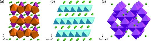
Crystal structures for (a) olivine LiFePO4 (Li in green, FeO6 in brown, PO4 in purple), (b) layered LiCoO2 (CoO6 in blue) and (c) spinel LiMn2O4 (MnO6 in magenta), which have 1D, 2D and 3D diffusion channels, respectively.
Layered materials make up the bulk of successful intercalation materials. These include lithiated transition metal oxides of the form LiMO2 (where M is some combination of Co, Ni or Mn) [41,74,81] for the cathode and graphite-based anode materials [107]. Alternative oxides like MoO3 [108] or V2O5 [79] dichalcogenides like TiS2 [34] and other 2D materials such as the emerging class of MXenes [109] have also received substantial attention.
In transition metal oxides, individual sheets comprise edge-sharing MO6 octahedra linked together in the ab-plane. Along the c-axis, the material alternates between transition metal and Li (or vacancies) in the octahedral sites (O), allowing 2D Li diffusion (Fig. 2b). The cubic closed packed structure repeats every third layer (ABCABC stacking) and therefore these compounds are classified as O3-type layered structures [110]. In layered Li-intercalation materials, this distinction is not important because the octahedral site is the most stable at all Li concentrations. However, when Na+ is the working ion, the situation changes slightly. The sodium ion is larger than both Li+ (Table 3) and the transition metals in the host material (∼0.7 Å) [111] and, as a consequence, sodium may be stabilized in larger trigonal prismatic sites [105]. The phase transitions between octahedral and prismatic coordination depend largely on the sodium concentration, while layer stacking (e.g. P2 vs. P3) depends primarily on the synthesis temperature—P3 being more stable below ∼700°C [90].
Since its introduction, LiCoO2 has been the most successful cathode material for Li-ion batteries—it combines high-voltage, reasonable capacity, and relatively fast transport of both Li and electrons into one material [35]. However, resource constraints on cobalt and limited stability at lithium concentrations below x ∼ 0.5 have driven the search for alternatives. Higher energy density and lower cost have been realized by replacing cobalt with nickel and manganese in various combinations [81,112]. The analogous nickel oxide, LixNiO2, has a comparable structure and high voltage, but low stability. The Ni3+cation is easily reduced to Ni2+, which is similar in size to Li+. The entropic driving force means some nickel ions migrate into the interlayer plane and inhibit Li transport. Likewise, layered LiMnO2 easily undergoes a layered-to-spinel transition and distortion that leads to loss of soluble Mn2+ ions. Two second-generation materials, LiNi1/3Mn1/3Co1/3O2 (NMC) and LiNi0.8Co0.15Al0.05O2 (NCA), have addressed these weaknesses of the individual transition metal oxides. A small fraction of the highly stable Co3+ ion is sufficient to prevent reduction and migration of nickel, while redox-inert aluminum serves to prevent over-oxidation in NCA. Similarly, nickel, manganese and cobalt have been combined in various proportions to take advantage of the low cost of manganese, high performance of cobalt and high voltage of nickel. Now, further developments have focused on third-generation materials such as the Li- and Ni-rich layered oxides. These materials boast large capacities in excess of 250 mAh/g by harnessing anion redox processes [113], but suffer from unresolved issues pertaining to voltage and capacity fading during long-term cycling. The nuances of these advanced materials have been more thoroughly discussed in recent reviews [81,112].
Other alkali layered materials with favorable electrochemical performance include a MoS2, which cycled with a stable sodium capacity over 230 mAh/g when prepared as a mechanically robust composite with graphene [114]. Vanadium oxides have been popular hosts for Mg-insertion [56], but recent findings suggest that a large fraction of V2O5 capacity in previous studies may be attributed to the effects of proton intercalation in the presence of trace water [115]. Using Na+ as the working ion, bilayered xerogel V2O5 showed uniformly superior electrochemical performance when iron was hydrothermally pre-inserted between nanobelt layers compared to the regular xerogel [116]. The iron binds adjacent layers more strongly, which decreased c-axis variation from 3.79 to 0.49 Å (Fig. 3). The capacity and capacity retention were both improved compared to the original structure (184 vs. 161 mAh/g and 80% vs. 62%, respectively).
![Schematic illustration of the layered vanadium oxide xerogel structure. (a) The normal xerogel structure experiences large lattice breathing during reversible sodiation and shows poor cyclability. (b) Pre-intercalated iron inhibits lattice breathing to improve structural stability and cycling performance. (c) Schematic illustration of the iron pre-intercalation process for forming thin vanadium oxide xerogel nanobelts [116].](https://oup.silverchair-cdn.com/oup/backfile/Content_public/Journal/nsr/4/1/10.1093_nsr_nww093/6/m_nww093fig3.jpeg?Expires=1750188846&Signature=bctdnDYRy-5UtXd2BFujdMIu-zsNcHlc97YdmKm38G~la4zeyJ5yaYw3vplij~P~7act-1~4iDSuKbggqJMveDe8esbQM0wvT73FhCIATdqPPQN8kayJa9Zd4izPLFO5fG7eZj1vP~YRy1g4efFCBHD~YQInHw6iyjfTn3L5ZXeK8j7zTWPJfOAqzhnKbNX3Gpg8OaPk-nDUJYDTZNQ49WkQLKZPAhOma6iSEWUtiC7X4LjCr6u5iXqMcGPtN0cgvkpN1LXPcw48xitHboWlzMg8fZYjdjBAyubdzpD0YAPswxazRzjnv3XtLLnXU3QoLWGvWteshlzJPHsJndgVhA__&Key-Pair-Id=APKAIE5G5CRDK6RD3PGA)
Schematic illustration of the layered vanadium oxide xerogel structure. (a) The normal xerogel structure experiences large lattice breathing during reversible sodiation and shows poor cyclability. (b) Pre-intercalated iron inhibits lattice breathing to improve structural stability and cycling performance. (c) Schematic illustration of the iron pre-intercalation process for forming thin vanadium oxide xerogel nanobelts [116].
At the anode side, graphite is the most successful anode material, although a wide array of other hard (disordered) and soft (ordered) carbons have been studied extensively [107,117]. In practice, almost all of the 372 mAh/g theoretical capacity is utilized, but the volumetric capacity is rather low (∼800 mAh/cm3) and the power density is limited to regimes where Li-plating does not occur [118]. Nevertheless, the simplicity of graphite has made it difficult to displace. Alkali–graphite intercalation compounds (GICs) form in stages. The driving force for the staging phenomenon is the tradeoff between the energy required to expand the van der Waals gap between graphene layers and the repulsion between adjacent alkali ions [119]. A stage n, GIC will have ions inserted between every nth layer and, in the case of lithium, it will vary from stage 1 (in LiC6) when fully lithiated down to stage 8 (LiC72) before being fully delithiated at voltages very close to those of metallic lithium (∼0.1–0.3 V vs. Li/Li+) [120].
Another major issue with graphite and other carbon anodes is the reduction of the electrolyte, which forms the solid–electrolyte interphase (SEI). The SEI serves an important purpose protecting the anode from further side reactions, but nevertheless consumes Li or other ions. This results in an irreversible capacity loss upon the formative first cycles of a battery. Proprietary SEI formation protocols are often closely guarded trade secrets that offer battery manufacturers their competitive advantages [121].
Spinels are structurally related to the layered oxides. For example, in LixMn2O4, the unit cell is composed of a cubic close-packed array of oxygen atoms and edge-sharing MnO6 octahedra. However, whereas the layered oxides have all metal octahedra in the same plane, each plane in the spinel has half of the possible octahedral sites occupied by Mn atoms (Fig. 2c). This forms a 3D diffusion network for the inserted ions, with octahedral interstitial sites connected by vacant tetrahedral sites. As with other LixMnO2 compounds, this material is low-cost, but also suffers from only modest performance. Jahn-Teller distortion (see the ‘Electronic structure’) and dissolution of Mn2+ into the electrolyte are two failure modes associated with manganese electrodes [122]. Along the same lines as the layered materials, replacing manganese with nickel or other dopants improves the performance and stability by reducing the fraction of unstable Mn3+ present in the structure [123,124].
The next most common spinel, Li4Ti5O12 (LTO), is used as an anode material. The structure is similar to LiMn2O4 except that one-sixth of the TiO6 octahedra have been replaced with LiO6. This material undergoes a phase-separating transformation to rock-salt Li7Ti5O12 upon discharge, where all the Li atoms originally on tetrahedral sites (8a) migrate to occupy octahedral sites (16c) [125]. Recent studies using scanning transmission electron microscopy (STEM) have shown that this reaction takes place with sharp coherent interfaces separating the LTO from the lithiated Li7Ti5O12 phase. In addition, electron energy loss spectroscopy and density functional theory (DFT) calculations show that the inserted Li+ and e– pair are strongly associated. That is, reduction of Ti4+ to Ti3+ takes place near the inserted Li (rather than homogenously distributing electron density over the Ti 3d orbitals) in order to maintain local electroneutrality [126]. The Ti-O bond length fluctuates as a function of Li concentration and depth within the particle. The bond distortions serve to form charge trapping centers that facilitate electronic transport via polaron hopping in what is otherwise a wideband gap material (3.8 eV) [127]. Despite the dynamic bond fluctuations, however, this material offers remarkably long life because the two end members experience almost no strain whatsoever (∼0.2% volume difference) and it operates at voltages high enough that SEI formation and Li-plating are mostly avoided. This means nanoscale LTO particles can be cycled at extremely high rates without resistive losses to the SEI or the dangers of short-circuiting the battery with Li dendrites. However, the high voltage (∼1.55 V vs. Li/Li+) also severely reduces the energy density compared to graphite. LTO is primarily employed where power and safety are more important than energy density.
In general, spinels have not been as successful as Na-ion electrodes. Na+ often does not fit into empty tetrahedral sites [90] or experiences orders-of-magnitude slower diffusion [128]. The exception to this has been insertion of Na+ into spinel LTO, which proceeds via a three-phase mechanism. Na ions occupy the octahedral 16c sites when the Na6LiTi5O12 (NTO) phase is nucleated. Simultaneously, Li in tetrahedral sites in LTO is simultaneously pushed into the octahedral sites, forming Li7Ti5O12 as an interphase boundary that propagates between the NTO and LTO phases until all the LTO is consumed. When the reaction is reversed upon charging, the extracted Na+ leaves behind vacancies that are backfilled by diffusion of Li into the tetrahedral sites. Therefore, the fully discharged product (NTO/Li7Ti5O12) forms LTO as the interphase boundary under this condition. As with lithiation of LTO, sharp interface boundaries are observed with STEM imaging upon sodiation as well [129]. Intercalation into Mg spinels such as MgMn2O4 is more encouraging (if suitable electrolytes are developed) and has been directly observed with a variety of characterization tools [130]. Furthermore, first-principles calculations suggest that both Mg2+ and Ca2+spinels may achieve high energy densities (up to 1000 Wh/kg) and reasonable activation energies for diffusion. In particular, the diffusion barrier for Ca2+ is comparable or smaller than that of Li+ [131].
The third major structure used for battery materials is the olivine family, and most notably LiFePO4 [44]. In this structure, distorted FeO6 octahedra share vertices with one another in the bc-plane. PO4 tetrahedra share one edge with one FeO6 octahedron, while the other two vertices form a bridge linking another FeO6 octahedron in the same plane with a third octahedron in an adjacent layer (Fig. 2a). The lattice allows diffusion of Li-ion in octahedral sites in a 1D channel along a curved trajectory [122] that is otherwise parallel to the b-axis.
LiFePO4 (LFP) has proven to be a hotly contested material [31] and its performance has sometimes outpaced the fundamental understanding behind it. At equilibrium, LFP shows a wide miscibility gap and separates into Li∼0.9FePO4 and Li∼0.1FePO4 (where the exact end members will depend on the particle size) [132]. However, unlike the phase-separating behavior observed with LTO, in situ experiments on LFP have revealed metastable LixFePO4 solid-solution behavior [133] and annular-bright-field STEM shows a metastable stage 2 lithium compound for Li0.5FePO4 [134]. This staging is driven by interlayer Li–Li interactions that result from strong correlation between Fe and injected electrons [135]. Further, staging is a size-dependent phenomenon. For particle sizes under ∼50 nm, formation of the stage 2 compound is energetically favorable compared to phase separating, while larger particles will have a three-phase coexistence of LiFePO4/Li0.5FePO4/FePO4 where the stage 2 interphase width narrows as the particle size increases [136,137]. Nano-particulate LFP allows extremely high-rate performance compared to micron-sized particles because the probability of defects obstructing the 1D channels is greatly reduced [138,139] and doping with Zr, Nb or Mg greatly improves electrical conductivity and power density [140]. However, despite favorable performance, the voltage and capacity are both relatively low compared to other commercial materials (Table 1).
Second-generation olivines incorporate other metal ions such as manganese to increase the voltage and improve solid-solution phase transition behavior [141,142]. Sodium and magnesium analogs of the phospho-olivines have been much less thoroughly studied. The best electrochemical performance of NaFePO4 was recently demonstrated after sintering at 460°C. The sample was amorphous at this temperature and delivered 143.5 mAh/g initially, of which 100.4 mAh/g was retained after 200 cycles [143]. On the other hand, magnesiation of FePO4 does not proceed by intercalation at all. Instead of Mg0.5FePO4, an amorphous surface layer composed of Mg3(PO4)2 and Fe3(PO4)2 was observed [96]. These reaction products are thermodynamically more stable than the intercalation product, suggesting that magnesium olivines are unlikely electrode candidates.
Prussian blue analogs (PBA) are another compelling class of up-and-coming positive electrode materials, especially for sodium-ion batteries [144]. PBAs are of the form AxM΄y[M”(CN)6]z·nH2O, where A is the metal ion that is reversibly intercalated and M΄ and M” are structural transition metals that may or may not be identical. A cubic metal-organic-framework (MOF) is formed when the M΄N6 octahedra and M”C6 octahedra are bridged together by cyanide bonds. Ferricyanide is often used as the C-coordinated source of iron (M”) metal centers, and the N-coordinated M΄ is often one or more of Mn, Fe, Co, Ni or other metals [145–147]. The wet chemical syntheses associated with these materials are expected to be low-cost and environmentally friendly at scale. This family of materials has been most thoroughly studied in the context of Na-insertion [144] but the large open framework allows fast ionic diffusion and little strain under the repeated insertion of many different ions, including Na+ [145,148,149], Mg2+ [150,151], Ca2+ [152] and many others [153,154]. These structural factors are expected to lead to good capacity retention and cyclic stability for both aqueous and non-aqueous batteries.
Na-intercalation PBAs have demonstrated the best performance to date. Controlling the stoichiometry is crucial for good electrochemical performance, as slow-grown crystals have fewer M”(CN)6 vacancies and less excess water. With fewer vacancies, the material is better equipped to accommodate strain and resist collapse during cycling, while less water content makes ionic diffusion faster. Near-stoichiometric (y/x = 0.94) all-iron PBAs grown slowly to sizes of 300–600 nm provided capacities of 170 mAh/g, which corresponds to full utilization of the material up to Na2Fe[Fe(CN)6]0.94. On the other hand, a rapid synthesis led to 20-nm crystals with more vacancies (y/x = 0.68). These lower-quality crystals only intercalated up to 1.3 Na per formula unit (140 mAh/g) and gave much poorer rate performance [145]. Comparable syntheses have been developed to produce PBA/carbon nanotube composites with excellent low-temperature performance. The composite maintained 142 mAh/g at –25°C and a 0.1 C rate (85% of the capacity at 25°C), while long-term cycling at a higher rate of 2.4 C still gave 76 mAh/g and > 99.4% coulombic efficiency after 1000 cycles at –25°C [148]. Similarly, an all-manganese PBA with only 1% vacancies at Mn(CN)6 sites has been shown to insert three Na ions per mole (209 mAh/g). This was possible because both the N- and C-coordinated Mn centers are redox-active, and the 7.8-Å-wide cages in the MOF easily accommodate two Na+ at a time in tetrahedral sites separated by 3.1 Å [155]. Future progress for high-capacity and long-lived PBA electrodes will have to take advantage of the metals that are redox-active at both positions (currently only Mn and Co are redox-active when coordinated to the nitrogen atom), while simultaneously mitigating the structural transitions that occur with the N-bound metal is oxidized or reduced [147]. Regardless of the structure, a successful battery material must accommodate the reversible insertion and extraction of alkali ions. The stability of the crystal structure depends on absorbing the combined effect of the steric and electrostatic influences on the original structure by the inserted ion, as well as effects pertaining to the electronic structure or phase transformations.
For layered oxides, the positively charged cation acts to stabilize the structure by counteracting the repulsion between the oxygens in adjacent layers, while also forcing layer spacing wider. The net effect is less than 3.5% strain in the c-axis upon discharge, coupled with minimal overall volume changes (±3%, depending on the change in the a-parameter [156]). In other layered materials like graphite and LixTiS2, van der Waals bonding between the layers dominates, so mitigating electrostatic repulsion is less significant. The steric effect of cation insertion leads to a larger variation in the interlayer spacing (∼10% for both cases [120,157]). The framework structures are better equipped to deal with strain upon intercalation of alkali ions, or co-intercalation of solvent molecules (Fig. 4). This helps prevent exfoliation of layers, as sometimes observed in graphite [85,158] or in Mg-ion intercalation materials, where the divalent ion is strongly solvated by the electrolyte [159].
![(a) Layered materials like graphite may be subject to co-intercalation of solvent molecules, which delaminates the structure and makes it more susceptible to other failure modes and side reactions [158]. (b) The framework spinel structure can only accommodate the inserted ion. Cations in the electrolyte must be desolvated before intercalation proceeds [160].](https://oup.silverchair-cdn.com/oup/backfile/Content_public/Journal/nsr/4/1/10.1093_nsr_nww093/6/m_nww093fig4.jpeg?Expires=1750188846&Signature=IF-3Gp4Bx8XwWooqJL2cKNi1lrMCADvTi2lg2pxyLUiuKiGA8YBCR6oyHowQ4xEih2LPxw0E7RIvi4urWXsnwbf2h3j2CfU7dGy~7zsB4wbeXOAZuw7-Y3pWiZ4frwwBqFkhQiRuE1JRoRep58ooSH4-wkEARGo11aXH6x2nt3vxwbd3FiF15ywVwQ~I2X8WNwwa6eljgFLz6E54ZUKqIGOShtjEAEHhCBaYzPfCfWLEsUPYsBwWJuSykl1hhyAipznwaOdH7o-NT4ECjYM-fXI1BDfDL9-u-F9QIVWTp-Vm82kAIvbwIyKh1BeiQpi27tkoImC9CEUbdQB9x3Z-pQ__&Key-Pair-Id=APKAIE5G5CRDK6RD3PGA)
(a) Layered materials like graphite may be subject to co-intercalation of solvent molecules, which delaminates the structure and makes it more susceptible to other failure modes and side reactions [158]. (b) The framework spinel structure can only accommodate the inserted ion. Cations in the electrolyte must be desolvated before intercalation proceeds [160].
Nevertheless, enhanced physical stability often comes at the cost of other properties, such as electronic conductivity. For example, the separated framework structure of LFP means that polaron hopping (the transport of bound electrons and induced lattice distortions) dominates in that material, whereas the wide band structure of materials like LiCoO2 or LiTiS2 gives rise to metallic conduction over a wide range of lithium concentrations [34,161]. Indeed, optimizing the myriad orthogonal properties in intercalation hosts is part of the excitement and challenge of battery science.
Electronic structure
For every Mn+ ion inserted into the host structure, n electrons must also be injected to maintain local electroneutrality. In general, this corresponds to the reversible redox processes at the transition metal centers, but the anionic effects are also significant. As such, the success or failure of various can often be explained by analysing the electronic structure as the host is oxidized or reduced. From the chemist's perspective, this requires molecular orbital theory, while the solid-state physicist considers how these orbitals combine to produce the band structure.
Jahn-Teller distortion is one example where molecular orbital theory is valuable, as it explains the instability of Mn3+ (Fig. 5a) [162]. Trivalent manganese has a high-spin d4 electronic configuration (t2g3eg1) with a degenerate ground state (i.e. the fourth electron occupies one of two equivalent eg orbitals). Here, the overall energy is lowered (equivalently, the degeneracy is broken) by elongating the bonds along the c-axis and contracting the bonds in the ab-plane. This reduces the overlap between the Mn3+ dz2 anti-bonding orbital and the apical oxygen atoms (note that the dz2 orbital is oriented along the c-axis) and increases the overlap between the dx2–y2 anti-bonding orbitals and equatorial oxygen atoms. This lowers the energy and the symmetry of the system, but leads to severe distortion (∼16% elongation in the c-axis relative to the a-axis) that imposes a large strain and rapid capacity fading in LiMn2O4 once more than 50% of the Mn cations are reduced to Mn3+ [43].
![(a) Schematic diagram demonstrating the change in energy for d orbitals when a cubic MnO6 octahedron undergoes Jahn-Teller distortion to a tetragonal configuration [83]. Simulated electronic density of states for (b) V2O5 and (c) Li0.5CoO2 [163,164].](https://oup.silverchair-cdn.com/oup/backfile/Content_public/Journal/nsr/4/1/10.1093_nsr_nww093/6/m_nww093fig5.jpeg?Expires=1750188846&Signature=WpYw0hI9~g5pzAXbCsfVycIV966MyqKZQaX-I5KwYcnDboo2ZlrZp-esDbrIks51t7JFAhfaknf9xsMUeXf2CKvOQq8t2yZNH~Na5pKRnwgc~dojjvPhfNAc4gNZjNuRG93rbNNta9~2mCZe-6SzBEeKqb1yBY8gFWEyr4NoC-7ZoH-b1Zp7XJcFONj7~-K8LCbYIU8-1H2JK63nZPbDhLk-kVJWkE-qop3JA8t565tbW14pqMhcgEH6Q8TwVxMIwiTI5q9ue5~bysJTIr~J2BT~FS2PzCd6kheLH3qCHSb1srWQ3w5lcM-xorsRUUHyRCduUTYfqPPXJUaNyN9Txg__&Key-Pair-Id=APKAIE5G5CRDK6RD3PGA)
On the other hand, the band structure of certain compounds predicts their stability as the Li concentration is varied. LixCoO2 is well known to become unstable for x < 0.5. This is attributed to the Co-3d band, which mixes strongly with the O-2p band (Fig. 5c) [163,165]. As the Co-3d band is oxidized, electron density is eventually removed from the O-2p band as well. Weakened Co–O bonds lead to the formation of peroxide ions O22– and subsequent oxygen evolution. By contrast, V2O5 has greater ionic bonding character, and minimal hybridization between the V-3d and O-2p orbitals (Fig. 5b). Little electron density is stolen from the O-2p band when LixV2O5 is fully oxidized, which is why we can speak about V2O5 but not CoO2. However, the stability of V2O5 comes at the cost of lower conductivity, one of the features preventing its commercialization—there are always tradeoffs!
While hybridization tends to limit performance in Li-ion cathode materials, it appears to be crucial for the success of multivalent battery cathodes. The Chevrel phases (CPs, MgxMo6X8 for X = {S, Se, Te}) [166] remain state-of-the-art for Mg-insertion compounds even 16 years after the seminar report by Aurbach et al. [94]. The rapid kinetics are attributed to the Mo6 octahedron. It can be reversibly oxidized and reduced to accommodate the four-electron redox process, meaning each Mo need only change its average valence state by two-thirds [167]. Similarly, strong hybridization between the (Ti, V) 3d and Se-4p orbitals led to electrochemical performances that were comparable to the CPs (∼110 mAh/g at ∼0.9 V vs. Mg/Mg2+) [168].
Besides the cation redox couple and cation–anion hybridization, the anion itself has been shown to influence the performance of intercalation materials. Sathiya et al. were the first to definitively identify reversible localization of O22– peroxide species using X-ray photoelectron spectroscopy (XPS) and electron paramagnetic resonance (EPR) spectroscopy [113]. Their Li2Ru0.5Sn0.5O3 served as a valuable platform for isolating the redox behavior of ruthenium and stabilizing the lattice with tin (as opposed to the more complicated case of the NMC cathode, which has three redox centers and lower stability). This discovery accounts for the high capacities of the Li-rich layered materials, as well as one of their failure modes (oxygen evolution).
These examples suggest that the ability to rapidly modulate oxidation states is an important factor that might lead to the design of high-energy-density Mg electrodes. Contrary to frequent claims, the electrostatic interactions of Mg2+ alone cannot explain slow rates and low utilization [167]. The recent discovery of reversible anionic redox capacity has further opened the door to materials whose capacities exceed 1 e– per transition metal [112]. While most studies are dedicated to the crystal structure of the intercalation host, paying more attention to the electronic structure is an underappreciated—and likely fruitful—avenue for future research.
Voltage
The battery voltage is the driving force (thermodynamically, the electrochemical potential difference) pushing alkali ions and electrons from one electrode to the other. We have recently provided a thorough treatment on the voltage [83] but will summarize key points here.
Here, the overall change in Gibbs free energy comes from the total energy of the cathode (GC) and anode (GA) at one state of charge relative to some initial concentration, x0. The total number of electrons transferred (n) depends on the valance of the working ion (z) and F is Faraday's constant. For simplicity, the chemical potential of the anode is usually that of Li |$(\mu_{A}(x)=\mu_{Li}^{0})$|.
Using the underlying thermodynamics, information about phase transitions can be read directly from the voltage profile (at sufficiently slow cycling rates) [169,170]. Solid-solution behavior arises when the enthalpy of phase mixing is non-positive (Fig. 6a). Then the chemical potential is a continuous function and the voltage decreases smoothly upon charging or discharging (Fig. 6b). However, if phase mixing is not spontaneous (i.e. ΔHmix > 0), local minima in the Gibbs free energy are observed (Fig. 6c). The first derivative of the Gibbs free energy is not continuous at the phase boundaries (hence the term first-order phase transition) and constant within them, leading to voltage plateaus (Fig. 6d). This behavior corresponds to two-phase mixtures [171] and cation/vacancy ordering regimes [172].
![The voltage profile of an intercalation material (LixMA) depends on the first derivative of the Gibbs free energy. (a) Solid solutions mix spontaneously which leads to (b) sloping voltage curves. (c) Phase-separating materials have positive enthalpies of mixing and (d) constant voltages in the miscibility gap [169].](https://oup.silverchair-cdn.com/oup/backfile/Content_public/Journal/nsr/4/1/10.1093_nsr_nww093/6/m_nww093fig6.jpeg?Expires=1750188846&Signature=I1FShEbC2GWcMMTmF57x9qVy7ht7eMJLubn5EbBvQkFh9zlI2VY1uguHzl2McR~BcT4oVb2w6JljCT01Bl3GREHrUkqwJ5n7ntg-IdHsh9J6dh7oN5SXOGdkmmHKc3DLV9~RPlaT9WLWQLrL0mANAPggrn7OPByxoHhLkDt3nJqzq90seSVbrSid~3Y85S4U9Bbj7OxgJacEK2Zlc9i-IkUFRDvTju-j9s0QqSKxuoj4TQVwqEm5UQ6i~e0IB5z~UpzjPU4iu6oHGhddT3W-gFHi-VtI4ln1Uls5BrmLeO5CmTeD4Ngtv8HSiNgA4ZPD2H8PUJ1A8n~2FtATQ2Jwsg__&Key-Pair-Id=APKAIE5G5CRDK6RD3PGA)
The voltage profile of an intercalation material (LixMA) depends on the first derivative of the Gibbs free energy. (a) Solid solutions mix spontaneously which leads to (b) sloping voltage curves. (c) Phase-separating materials have positive enthalpies of mixing and (d) constant voltages in the miscibility gap [169].
A complete understanding of the voltage depends on the chemical potential of working ions and electrons [173] plus their interactions [174], which makes quantitative separation of electronic and ionic components arbitrary [175]. However, distinguishing between these effects aids qualitative understanding. The main contribution to the voltage is the difference in Fermi levels between the anode and cathode. It is also influenced by the chemical potential of the intercalated ion in different crystallographic sites or phases and local perturbations to the electronic structure via defects.
One of the main drivers of the electrode voltage is the energy level of the redox couple of the transition metal (or anion as discussed previously). This depends on the oxidizing power of the redox-active species at a given valence state, which can be roughly explained by invoking the ionic radius and Slater's rules for determining effective nuclear charges [176]. Going across the period of 3d transition metals, adding protons reduces the ionic radius and leads to an increase in electron binding energy (higher voltage). This remains true even as the number of d electrons increases because electrons in the same orbital only shield the nuclear charge by 0.35. Going down one period to the 4d transition metals leads to more complete shielding from inner electrons and a larger, more diffuse electron cloud. The electrons are less strongly bound in the 4d metals and have a lower voltage as a consequence.
The anion in the host framework also affects the electrode voltage. The two main contributions are the limits imposed by the anion np band and the inductive effect on the transition metal. Both are related to the electronegativity of the (poly)anion in question. Whittingham's LiTiS2 battery was the first major demonstration of a rechargeable intercalation battery [1]. However, one of the fundamental drawbacks of this chemistry and the chemistry of all chalcogenides is relatively high energy (low voltage) of the S-3p band (∼2.6 V vs. Li/Li+) [2]. Insofar as the only reports on anionic redox are in oxides [3], limits on the voltage are only rarely compensated by additional capacity. Instead, shifting focus to oxides with lower energy O-2p bands led to the discovery of LiCoO2 and other 4-V cathodes [2,4].
Similarly, the electron-withdrawing power of the anion explains its inductive effect on the voltage. Metal phosphates are higher-voltage materials than oxides with roughly the same bonding lengths and metal centers (LiCoO2 is ∼4 V compared to ∼4.8 V for LiCoPO4, for example [177]). The difference arises from the enhanced electronegativity of XO4n– polyhedra [178]. The ionic character of metal–oxygen bonds is increased and the associated lowest unoccupied molecular orbital (LUMO) is dragged down to lower energies [179]. Tavorite structures also show the inductive effect. The presence of F in the LiMXO4F structure shows even greater ionic bonding character between M–O bonds and correspondingly higher voltages [180].
Similarly, the effect has been extended to conversion anodes [181]. Increasing the covalent character of the Mn–X bond gave rise to a redox couple at 0.30/1.10 V vs. Li/Li+ for MnNCN (Fig. 7a), which is slightly lower than the 0.35/1.25 V couple observed from cyclic voltammetry on MnO. The longer bond lengths and higher covalent character relative to MnO (57.4% vs. 40.9%) were implicated in raising the energy and decreasing the voltage (Fig. 7b).
![(a) Crystal structure of MnNCN. Mn ions are coordinated to form MnN6 octahedra and carbon bridges the gaps to connect N atoms on alternating layers. (b) The coordination of metal centers and energy levels of MnNCN and MnO. MnNCN is more covalently bound than MnO because C and N are both less electronegative than O [181].](https://oup.silverchair-cdn.com/oup/backfile/Content_public/Journal/nsr/4/1/10.1093_nsr_nww093/6/m_nww093fig7.jpeg?Expires=1750188846&Signature=eo-rNcrdxM6DzSlBx4rtX9L3DGCj7AmBAcNDwnsd5fv~TQI196UcyPfXNrX3uBR98faZOKdHf7uufVL2IrHgKMiIwMSMrOjRGKaPWOCE~AdToBAwEoKl6SAreqzsyg-zM-pLg0n0V6CWEP26GKWn-YaB1s1TTADBMWU18vVEKkwRWxWhp6trW6zE1f~QjbUemlwc6iDQDtgmmev6UPvPufxDuoes74HsXEcoU0zD6eIcKgasBUrEXVOlS7QLHpRcS2CMk7pw29XyTv3U-xLMhYIe-bgEp5JOfT7KKqD7yykRk~uZ6O6I8zH5HM6Ry5M7iKZZ8jLsTIbhlisL7BTdQw__&Key-Pair-Id=APKAIE5G5CRDK6RD3PGA)
(a) Crystal structure of MnNCN. Mn ions are coordinated to form MnN6 octahedra and carbon bridges the gaps to connect N atoms on alternating layers. (b) The coordination of metal centers and energy levels of MnNCN and MnO. MnNCN is more covalently bound than MnO because C and N are both less electronegative than O [181].
However, the Fermi energy of redox species alone cannot explain voltage effects. A full understanding includes the effect of the chemical potential of the inserted ion in the host. The best example of this is LiMn2O4. For 0 < x < 1, lithium inserts at a potential of ∼4 V into Mn2O4 spinel tetrahedral sites (Fig. 8a). However, for the exact same redox couple in layered LixMnO2, the voltage is only ∼3 V at octahedral sites [182]. Further, for x > 1, a drastic reordering of Li takes place and all subsequent intercalation occurs at the octahedral sites, also at 3 V. At low Li concentrations, Li ions are more stable in the four-fold tetrahedral environment [183]. But Li+–Li+ repulsion becomes more important at concentrations above x > 1, and the overall energy of the system is minimized by ordering Li at the higher-energy octahedral sites. The increase in site energy offsets the electronic stabilization from Jahn-Teller distortion, as described above, leading to a large 1-V difference.
![(a) The cubic spinel Mn2O4 intercalates Li at voltage plateau of about 4 V in tetrahedral sites, but redistributes Li to lower potential octahedral sites (∼3 V) once the tetrahedral sites are filled [83]. (b) The profiles of discharge curves of LiCoO2 with different particle sizes. The steep voltage profiles for smaller crystal sizes indicates capacitor behavior becoming more dominant. (c) Expected discharge potential curve for nanocrystalline LiCoO2. Capacitor behavior is expected for the intercalation of Li ions into the surface layers. The site energy on the surface exceeds that of the bulk, and the external energy needed for ion transfer decreases, leading to reduced potential plateaus [184].](https://oup.silverchair-cdn.com/oup/backfile/Content_public/Journal/nsr/4/1/10.1093_nsr_nww093/6/m_nww093fig8.jpeg?Expires=1750188846&Signature=dihuDt5K5is2jYnl-M57NNoPR7IUJczi92z2dtlTSQyVI3UhV3EaFY6S4G52egun3J4mY2xOvQSkf3D3PfP4xkvdwdMrCRgxV2iPe5YCCSXy4XawaEUuq9PXCzypGiARfAIcHNDycDAYJL4i4j04GlLfyv3fM3cz1jpx3NnjXkOKkNhxCkRGcn7O0UcUWBcG3hAqanTccF0TI7b50Lmf-aJjnf9Rcgtr7zUf0jwuvbKvPxgoWPIxbWFyAhOjWZSnDp~DVM-qH1tv7kiwX2DwW3iWFX3scQEvNiuDFYDfvbT781wVyVPJa0PFVUrPt2T~6JBi-YewvXaOdIaBOxr7QA__&Key-Pair-Id=APKAIE5G5CRDK6RD3PGA)
(a) The cubic spinel Mn2O4 intercalates Li at voltage plateau of about 4 V in tetrahedral sites, but redistributes Li to lower potential octahedral sites (∼3 V) once the tetrahedral sites are filled [83]. (b) The profiles of discharge curves of LiCoO2 with different particle sizes. The steep voltage profiles for smaller crystal sizes indicates capacitor behavior becoming more dominant. (c) Expected discharge potential curve for nanocrystalline LiCoO2. Capacitor behavior is expected for the intercalation of Li ions into the surface layers. The site energy on the surface exceeds that of the bulk, and the external energy needed for ion transfer decreases, leading to reduced potential plateaus [184].
Site energy also explains surface effects on the electrode potential. As the particle size of LiCoO2 is reduced from the bulk material to ∼6 nm, capacitor-like discharge behavior (V = V0 – Q/C) becomes more prominent (Fig. 8b). As particle size decreases, more of the intercalation takes places at surface rather than bulk sites. These high-energy surface sites have longer Co–O bonds and weaker binding between Li and the host (Fig. 8c), leading to lower voltages as bulk intercalation is progressively replaced by a surface capacitance mechanism [184].
Defect engineering is also a versatile method of manipulating electrode properties—including voltage—and often times improving many properties at once [185]. Cation doping is the most popular method of controlling defects [186–189] but increasing disorder with anion substitutions [190], control of oxygen activity [191,192] and crystallinity [143,193] have also proven to be effective.
As one recent example, Ni2+ substitution of V5+ in V2O5 augmented the voltage [194]. The Ni2+ induces disorder by (i) modulating the crystal field to reduce splitting of d orbitals and (ii) altering site energy by reducing repulsive forces on Li by the host cations. Both contributions lead to a moderate increase in voltage compared to the undoped sample (Fig. 9a).
![(a) Galvanostatic charge/discharge curves of Ni2+-doped V2O5 and undoped V2O5. Ni2+-doped V2O5 has a higher average potential and larger specific capacity than undoped V2O5. Defects introduced by low-valence Ni2+ plays a key role in enhancing the comprehensive performance [194]. (b) Discharge curves of crystalline and amorphous V2O5 in a sodium battery. Amorphous V2O5 possesses a higher average potential and larger specific capacity than crystalline V2O5 [193].](https://oup.silverchair-cdn.com/oup/backfile/Content_public/Journal/nsr/4/1/10.1093_nsr_nww093/6/m_nww093fig9.jpeg?Expires=1750188846&Signature=aykG5IVNrDhSOu10lOhgc4BYeDdK19MPg7eq0tjmgKKOsSzJ-E99kJrfq7UfgyScjy3N-X11nNsjbBTAKigZ8YasIRk2CXkMgG0m9BkgsHB6IIPtembc9ffQ1Jg--9t2puGXYUSBUm2f9kGVQDWK0hq-5mfp3NYUJ0~1od9OIL5AooQqLs3xww5fsZpo-Xmtk811V7H9CkiEe4InK3BpZXWi6XdBG-pJr14caH9-3SthBgcyZGB3AgROykcZ8VqC7Uo933WPRguYmEN-2IYpZ9V18SJVHzLVDeR99DRfYcwOQ2is~xLhSFf~7~1PBB7mK6S8LjV5nqHxeKoxYnS2mg__&Key-Pair-Id=APKAIE5G5CRDK6RD3PGA)
(a) Galvanostatic charge/discharge curves of Ni2+-doped V2O5 and undoped V2O5. Ni2+-doped V2O5 has a higher average potential and larger specific capacity than undoped V2O5. Defects introduced by low-valence Ni2+ plays a key role in enhancing the comprehensive performance [194]. (b) Discharge curves of crystalline and amorphous V2O5 in a sodium battery. Amorphous V2O5 possesses a higher average potential and larger specific capacity than crystalline V2O5 [193].
Reducing the crystallinity of V2O5 had an even more powerful effect on the voltage. Amorphous V2O5 vastly outperforms crystalline V2O5 as a Na-insertion material [193]. Along the same lines as Jahn-Teller distortion, this can be explained using ligand field theory [195,196]. The coordination of anions around the metal center induces the splitting of otherwise degenerate d orbitals according to the orbital geometry, whether it is bonding or anti-bonding, and the interaction between the ligand and the metal (cf. Fig. 5a). The disordered vanadium at-oms in amorphous V2O5 no longer occupy a periodically repeating lattice. Instead, no d orbital splitting takes place and a wide distribution of site energies are possible, which gives rise to a high, sloping voltage profile relative to crystalline V2O5 (Fig. 9b).
To summarize, the energy stored in a battery depends on its capacity and its voltage. Both parameters are intimately connected to both the crystal and electronic structures of the host material. High capacity requires a wide range of possible lithium concentrations in the host material, plus a versatile redox couple or couples to maintain electroneutrality. For high-voltage operation, the redox couple in the cathode must be low in energy compared to the anode (e.g. Li metal or graphite). However, the chemical potential of Li in different crystallographic or surface sites will also affect the voltage, and should not be overlooked. Different cation and anion substitution strategies will perturb the local crystal and electronic structure to further modify the electrode potential and other properties.
BATTERY POWER
where I is the current drawn, V is the cell voltage and Rint is the internal resistance of the cell. This is to say that dissipative losses scale faster than the useful power draw, hence the classic tradeoff between energy and power observed with the Ragone plot [197]. Therefore, the internal resistance must be kept to a minimum for high-power applications like electric vehicles. This internal resistance will depend on a number of factors: the electronic conductivity of the electrodes, the ionic conductivity of alkali ions in the host and in the electrolyte, and the reaction kinetics at the surface.
Electrochemical kinetics
![Discharge profile of a battery showing the effect of the different types of polarization [198].](https://oup.silverchair-cdn.com/oup/backfile/Content_public/Journal/nsr/4/1/10.1093_nsr_nww093/6/m_nww093fig10.jpeg?Expires=1750188846&Signature=H~6zw911aQJzERYIInV9J700tPBWTeqf~ez5qW8EpeM2tKMvr3igLYCqOv-67TLz2UmSIaeAUqnEY1l6L6dfbYV~xuXQS4LYArdDv43Avb6bWYsq6ROOQttz0xb1VLVbLVQlBbQRE0mLdnOPA-NAhzyzu8hZElB7H0G9h1Dr3qMbxsqyfZVp8S9WmcQa2c~8VR17-ltGNbGxJL4u7zunnlnnabLObdEf2lVJdgJ7DFtLDdynU2LfAg9UPfx7~98RpLhcEB7OOE0vj~5iX2Wlajou9Mob3y2-WjMLF3tcHU3ufOUcpNXYiWH8HZlPm5~MA2pcB0Wz3MrqKqgsnGHOtg__&Key-Pair-Id=APKAIE5G5CRDK6RD3PGA)
Discharge profile of a battery showing the effect of the different types of polarization [198].
Ohmic losses are attributable to the ionic resistance of the electrolyte and the electronic resistance of the electrode. The bulk electrolyte resistance is usually quite small and is not a major source of overpotential in a well-designed battery. However, it can be affected by the salt species and concentration as well as the solvents chosen as determined by the power requirements for the final device. Since many electrode materials are insulating or semiconducting, carbon additives are used to increase the overall electronic conductivity of the composite.
Here, Cbulk and Csurf are the bulk electrolyte concentration and concentration at the electrode surface, respectively, and the other constants have their usual meaning. As the surface concentration is depleted, this resistance increases, although it is difficult in practice to decouple this overpotential from typical sloping behavior at the end of the discharge cycle (see the ‘Voltage’ section).
where j is the current density, j0 is the exchange current density (a measure of the intrinsic kinetics of the reaction process), α is the charge transfer coefficient, V is the electrode voltage and E0is the equilibrium potential. However, the presence of porous structures and phase transformations complicates this analysis. Significant advances by Bazant et al. [201–203] have aided understanding and generalized the Cahn-Hilliard equations for phase-separating materials with Bulter-Volmer kinetics and Marcus theory for electron transfer.
Transport kinetics
These various sources of overpotential are minimized when the electronic and ionic conductivity are optimized simultaneously. Reducing the mechanical strain experienced upon intercalation and the energy required to nucleate phase transitions are also beneficial strategies for achieving high-rate performance. But, despite the critical importance of mixed conduction in developing batteries with high power density, a strong fundamental understanding of the underlying processes is somewhat lacking, and conflicting data are sometimes reported [204]. This is partly a consequence of the difficulty of extracting intrinsic material properties from electrochemical experiments, which often use composite electrodes with complicated surface and interfacial properties. A greater appreciation for defect chemistry [173] and the help of first-principles methods of computation [122,205] will help to compliment experiments and accelerate development in this area of relative weakness.
Electronic conductivity
Electron conduction in electrode materials proceeds by one of two mechanisms. Materials like LixCoO2 and LixTiS2 are metallic conductors at certain Li concentrations [161,206], which contributes to their attractive rate performance. On the other hand, LiFePO4 does not have wide conduction or valence bands that allow delocalized conduction. Instead, polaron hopping—the localized hopping of electrons and their induced lattice distortions—is the dominate mechanism for electron transport.
Carbon coating is the most common method to increase the electronic conductivity of a matrix using a scalable, low-cost process [207]. To a much lesser extent, defect chemistry has been used to rationally predict changes in electronic and ionic conductivity [191,208]. In the case of TiO2+δ, controlling the non-stoichiometry (δ) revealed a tradeoff between electronic and ionic conductivity in the case of strong electron trapping. While carbon coating and related nanostructuring techniques [209] largely mitigate electronic limitations on conduction, defect chemistry represents an underutilized design tool for optimizing the chemical diffusion coefficient [173].
Ionic conductivity
Unlike electronic limitations, transport of Li or other ions in the host matrix is more difficult to modulate, and has been the subject of many first-principles studies [122,180]. Density functional theory has been successfully applied to calculate the preferred diffusion path and associated activation energies for migration, among other properties. In layered oxides like LiCoO2, Li migrates from one octahedral site to another via an intermediate tetrahedral site with a small diffusion barrier of ∼0.3 eV (Fig. 11a) [210]. In spinel LixMn2O4, Li is transported between tetrahedral sites via the octahedral site for x < 1 and the activation energy is ∼0.4 eV (Fig. 11b) [122]. Olivine LiFePO4 originally was not predicted to have good power capabilities [44] but Li transport along a curved oct-tet-oct trajectory along its b-axis takes place with a small barrier of ∼0.2 eV (Fig. 11c) [211].
![Diffusion pathways for Li in (a) LiCoO2, (b) LiMn2O4 and (c) LiFePO4 [122].](https://oup.silverchair-cdn.com/oup/backfile/Content_public/Journal/nsr/4/1/10.1093_nsr_nww093/6/m_nww093fig11.jpeg?Expires=1750188846&Signature=2E9mHI4M5ujp4wjg3xf6QgCx0KAv9xWCJETHvwprNkv3N9JfR2PhFM3w2caU6TUvywOmdV8IgnSeFXefsntB6ce8DO~6A1VIegYh2QOEn~GRzUU~7zVD2OXJQQRYUmv95~-QIfZoB9ommoQx-0PPoP2AvTeX~hlgvHtkfGjP8uf23cttwCm8HvuPmVCra32MJ0P5eC68YWDlnwbuVDot3Jt36O60Jx-~0zkLS9gnnGE1f9v8VJ1RhSm5XgoQuQjM-G~e-tvvGyF~eZTS228plIVdZGNsvBvhVkgG4v59B4MsqAJi88j18zfarjUQTh9sm8aly9G34PWKbfg3lposRQ__&Key-Pair-Id=APKAIE5G5CRDK6RD3PGA)
Diffusion pathways for Li in (a) LiCoO2, (b) LiMn2O4 and (c) LiFePO4 [122].
LiFePO4 has been a particularly interesting case study for ionic transport. The pessimistic initial rate performance and wide spread in reported diffusivities were a source of some confusion [212]. Identifying the particle size dependence was one finding that resolved some of the discrepancy [139]. The excellent rate performance of nanoscale [138] (∼50 nm) LiFePO4 compared to bulk was achieved by reducing the particle size. Particles larger than a few hundred nanometers are effectively shut down even at defect concentrations of ∼0.5%, because of the high probability that the 1D diffusion channels will be blocked off by antisite point defects.
Other strategies for layered materials such as tuning the interlayer spacing [213] and incorporating structural water (e.g. in xerogels [214,215]) have been shown to reduce the diffusion barrier and improve rate performance in Li-, Na- and Mg-ion batteries [159,216]. Improved Li-intercalation in xerogel V2O5 [192] and Mg-insertion into MoS2 are two such examples of these strategies [213]. Nanostructures that reduce the diffusion length and maximize surface area are another well-worn path to increasing power density [80,217]. For one recent example, electrospun LTO and Li3V2(PO4)3 (LVP) were used as the anode and cathode in a high-power-density battery [218]. The energy density was relatively low owing to the high voltage (1.5 V) of the LTO anode and modest capacity of the LVP cathode (∼110 mAh/g). Nevertheless, the large surface area and safe, robust operating conditions led to minimal degradation over 500 cycles and enormous power densities over 12 W/g, which is competitive with supercapacitors (Fig. 12).
![(a) Rate performance and (b) voltage profiles at different rates for a full cell LVP//LTO battery. (c) Cycling stability of the battery charged and discharged at a 5-C rate. (d) Ragone plot shows the LTO//LVP battery has superior performance compared to other reported capacitors [218].](https://oup.silverchair-cdn.com/oup/backfile/Content_public/Journal/nsr/4/1/10.1093_nsr_nww093/6/m_nww093fig12.jpeg?Expires=1750188846&Signature=TiBXbBoFQwl-02DtWwIRzZj00eTfqjXO1PJmXVGm7ExiQDEdPb56mq~QQAroLBeWBlfSteXh6969Mv45aoGG0iVRt4AO2AV2Nr075Vzqd0mKhB-j69kwohKoC0vIaeA-Bw5akdelkHgY39oRFACtj4XSUslt7KUA9-Ak9kkJqzSwoNVbx6vp6S8yIXhVd7HshXiM1vlQMWQxEDZQUeNzRrqd795fD6r5BQjMMDp6EUMkj3ZClSgArtLXum4gvdAewcbbJROWupVsC3VHkgrtY8rAG6L1pynYR1DOJQc7hyy2NY2OKPZ-jPzQFeaoEyFLvSy0pTtjDdzPiHajE9ftEA__&Key-Pair-Id=APKAIE5G5CRDK6RD3PGA)
(a) Rate performance and (b) voltage profiles at different rates for a full cell LVP//LTO battery. (c) Cycling stability of the battery charged and discharged at a 5-C rate. (d) Ragone plot shows the LTO//LVP battery has superior performance compared to other reported capacitors [218].
The topology of the ionic pathway is especially critical for multivalent batteries. Ceder and others have made several contributions to correlate the diffusion energy barrier to the coordination environment of the cation within the host structure [219–221]. The nudged elastic band method was applied to identify the diffusion path and its associated energetics for the same cations in the δ-V2O5, one of two polymorphs that differ in their layer stacking (Fig. 13a), as well as other compelling cathode materials: spinel Mn2O4, olivine FePO4 and layered NiO2. While they recovered the expected trend with valence state (i.e. higher-valance cations experience higher diffusion barriers), their analysis showed a wide dispersion in energy barriers for divalent cation migration.
![(a) Structure of α- and δ-phases of V2O5. Adapted from ref. [221]. (b) The activation barriers for diffusion for five ions through (a) α-V2O5 and (b) δ-V2O5. Dashed and solid lines correspond to the diffusion when the host material is charged and discharged, respectively [219].](https://oup.silverchair-cdn.com/oup/backfile/Content_public/Journal/nsr/4/1/10.1093_nsr_nww093/6/m_nww093fig13.jpeg?Expires=1750188846&Signature=kfdRvVtVaA260pKWGjBy6WF7yLM2J4Gf4cowpFj9XXXNJmGYm1WYeLbtt5gqFN~-yErCrmuKrQtjZEW9flAOk~tTJLzyu~BasfN1b4f22Ke92vZRoevgyfUDU76FCwHT4SfwN7pF2~bWhSeqgLpgJWX1HbVibifabKsm5Yuw6t58TuDNOXdasnLea60NCItxW9LJmGbtbENv3Wi7wlPJhwBDaxRzxycYeTxIf4WHBRnhmXXjJXigPFcMotdewVokl-xfikivA28dXCG7eYZNVnYPlAVRyDOaY4BuIchQwdwEwJnHkg0OMtZMqzqoRWoapwMrYfWQB~zDrEfiDBIY1Q__&Key-Pair-Id=APKAIE5G5CRDK6RD3PGA)
For example, a low barrier of ∼200 meV for Ca2+ is observed in δ-phase V2O5, but this becomes as high as ∼800 meV for Mg2+ diffusion. However, in α-V2O5, the Ca2+ barrier soars above 1700 meV and, for Mg2+, it increases to ∼1000 meV (Fig. 13b). These differences depend on the preferred coordination number of the cation in question and the topology of the diffusion path. Ca2+ prefers to be coordinated by eight anions and Mg2+ prefers six. In the α-phase, the stable cation site is coordinated by eight oxygens and must pass through a three-coordinated face corresponding to an activated state (8→3→8). However, in the δ-phase, the cations pass through the same path as described by Zhou et al. [221]. Along this path, the cations are first coordinated by four oxygens with ∼2-Å-long bonds and two additional oxygens by ∼2.33-Å bonds (“4 + 2”) and diffuse by passing through two three-coordinate activated states separated by a five-coordinate local minimum before reaching the next stable site (“4 + 2”→3→5→3→“4 + 2”). Thus, for the α-phase, Ca2+ must start in its most stable coordination environment, then break five bonds before migrating to the next site, resulting in the large energy barrier. On the other hand, Ca2+ in the δ experiences a less severe change in bonding environment and never achieves its preferred coordination number, resulting in the low-energy barrier. The reasoning is similar for Mg2+: the “4 + 2” site is quite stable and requires an appreciable amount of energy to displace it along the rest of the δ-phase diffusion path (∼800 meV), but the severe change in α-phase coordination results in a slightly greater barrier (∼1000 meV). The best way to enable high ionic conductivity is to use materials whose diffusion path is composed of sites of approximately equal energy, such as those found in bcc-anion lattices [222].
Hence, the topology of the structure is shown to play an integral role in determining the diffusion barrier, which has several implications. First, high-rate multivalent batteries should benefit from matching cathode materials with cations that have dissimilar preferred coordination environments compared to the most stable intercalation sites. Forming such a metastable compound on discharge reduces the voltage but increases safety. At the same time, synthesizing Mg-containing cathode materials directly is not advisable, as this likely yields Mg in a stable site with high diffusion barriers.
There are some discrepancies to be addressed between these studies that arise from differences in the computational procedures. Current models cannot yet simultaneously capture all the various physical and chemical phenomena and future experimental work should try to confirm these findings. Nevertheless, computational materials science is rapidly becoming a valuable tool that will only become more useful as processing power increases. The conclusions drawn from these studies should inform the design of high-energy density multivalent cathode materials.
Phase transformations
First-order phase transitions are often treated as a liability in electrode materials. Nucleation and growth of the new phase may not proceed at appreciable rates needed for high power, and coherency strain between the separated phases can cause fracturing and hurt electrochemical performance [156,223]. However, the best-studied phase-separating material, LFP, has demonstrated excellent rate capability despite these misgivings, and a surprising number of conflicting claims have been made in the literature [212]. New results on this material have recently begun resolving some of these discrepancies, which highlight how phase transfer kinetics relate to high power density. Some examples include the existence of intercalation pathways away from equilibrium, the fraction of particles actively taking place in reactions at any one point.
The ∼7% volume difference upon transformation from LiFePO4 to FePO4 and back [44] contradicted the general thinking that large volume changes must be avoided at all costs to enable long cycle life. Malik et al. [224] used DFT calculations to show that, while classical nucleation theory cannot account for the lithiation mechanism, the existence of a low-energy non-equilibrium pathway does. The free energy of mixing for this solid solution is ∼15 meV per formula unit more energetic than the phase-separated state, and is thus accessible at moderate overpotentials (cf. kT, ∼26 meV at room temperature) [212].
However, Cogswell and Bazant [225] used phase-field methods to postulate a size-dependent nucleation mechanism, whose energy barrier vanishes below a certain critical size. To resolve this discrepancy, Liu et al. [226] recently confirmed that LFP does in fact form a non-equilibrium solid solution, and thereby bypasses nucleation and growth steps. Ex situ X-ray diffraction (XRD) studies have only been able to observe either the Li-rich or Li-poor phases. However, in situ synchrotron XRD studies showed that high current densities (i.e. high overpotentials) drive the system away from equilibrium and into a metastable state that quickly relaxes to the equilibrium configuration. (More generally, these results also have implications for other cathode materials, where transformations other than those indicated on their phase diagram may hold the key to overcoming sluggish reaction kinetics.)
Orvananos et al. [227] have shed more light on this situation by investigating the phase-separation kinetics of LFP. Phase separation can proceed by intraparticle segregation, or by interparticle exchange of Li, where one adopts a fully lithiated state and the other fully delithiated. The later dominates when, for example, slow kinetics or coherency strain inhibit a two-phase regime inside the same particle. As such, phase separation is suppressed kinetically for particles at low current densities and thermodynamically below a critical size. Their model predicts the order of particle lithiation and voltage response for two differently sized particles over a range of current densities. At low currents, they find that the smaller particle will lithiate first in the case of both particles undergoing intra- or interparticle phase separation owing to larger area to volume. However, when only the smaller particle has the intraparticle mechanism suppressed, lithiating the larger particle first is more favorable, since the two-phase path decreases the free energy, while lithiating the smaller particle in a single phase increases it. Although challenging to observe, this can be used to elucidate the reaction mechanism in LFP electrodes. Consistently with ref. [228], they also found that high current simulations resulted in concurrent lithiation.
Another controversial point involves the fraction of particles that undergo intercalation at any one point in time. Ideally, the active population is kept as high as possible so as to avoid current hotspots that might adversely affect the material's longevity. This condition (concurrent intercalation) has historically been a convenient assumption, but impossible to observe. However, some recent high-profile studies maintain that the reaction proceeds on a particle-by-particle basis. Delmas et al. [229] suggested a ‘domino-cascade’ model, after an electron microscopy study showed that electrodes charged to different nominal lithium concentrations only ever revealed fully lithiated or fully delithiated particles. In the particles they looked at (∼100 nm), they reasoned that coexistence of two phases in a single nanoparticle is unfavorable. As a consequence, the growth kinetics are much faster than the nucleation steps, and the ensemble of particles quickly transforms to FePO4 once delithiation begins.
Building on this, Dreyer et al. [230] showed that the voltage hysteresis observed upon charge/discharge of LFP is also explained by a particle-by-particle reaction mechanism. The open circuit voltage fluctuates by ∼80 mV, depending on the history of the electrode, indicating the absence of a true equilibrium potential, even as the applied overpotential tends to zero. They reasoned that electrochemical methods (cyclic voltammetry, potentiometry, etc.) can control the total amount of Li intercalated, but say nothing about the Li content for a given particle. They developed a multi-particle model that justifies how the non-monotone chemical potential of a single LFP particle will give rise to the observed hysteresis and very flat charge/discharge profile when taken to the limit of a large ensemble of particles.
A recent study by Li et al. [228] reconciled the particle-by-particle mechanism with the observations of concurrent intercalation by identifying how the current and direction of charging impact the mechanism. The found that charging (delithiation) proceeds with an active fraction of ∼5%, in general agreement with the particle-by-particle pathway. (Here, the active fraction was defined to include particles with Li concentrations nominally in the LixFePO4 miscibility gap, with 0.2 < x <0.8.) In contrast, during discharge (lithiation), the active particle fraction scaled with the current rate. X-ray absorption spectroscopy (XAS) and transmission electron microscopy (TEM) analysis indicated an active fraction of ∼32% at a 5-C rate (i.e. complete discharge in 1/5 hours). They also used a phase-field porous electrode model, incorporating coherency strain and Butler-Volmer insertion kinetics to predict a maximum active population fraction of 65% at a critical current density of ∼9.5 C. Interestingly, below this critical current rate, the local current density for a given particle remains constant, but the active fraction increases, whereas, above this current rate, the electrode responds by increasing the local current density of the available active particles. This result provides general insight into designing other battery cathodes as well, and suggests that by tailoring the phase transformation barrier in phase-separating materials. Reducing this chemical potential barrier (e.g. by nanostructuring and doping the host material) reduces the reaction overpotential, thereby enhancing the active particle fraction and current distribution.
Using LiMnyFe1-yPO4 (LMFP, a so-called second-generation LFP material) as a model system, Ravnsbæk et al. [141] correlated the strain energy associated with phase transformation to the rate capability of the material. Operando XRD showed that, for very high or low manganese content (y = 0.8 or 0), lattice mismatch between the charged (either MnyFe1-yPO4, MFP or FePO4, FP) and discharged (LMFP, LFP) states was greatest, and the two distinct phases coexisted (Fig. 14c). However, an additional metastable LixMnyFe1–yPO4 phase with hysteretic charge–discharge behavior emerges at intermediate manganese content (e.g. Fig. 14a and b). For y = 0.2, a fully continuous change in unit cell volume was observed upon discharge, suggesting solid-solution behavior. Similarly, the high-rate performance (up to 50 C) was maximized for y = 0.4 (Fig. 14d and e). Therefore, mediating the strain for both the LMFP ↔ LxMFP and LxMFP ↔ MFP transitions may be a compelling potential route to high-power batteries. More work is needed to clarify the molecular mechanism for this behavior, however.
![(a–c) Unit cell volumes (top) and operando diffraction data (bottom) for the phases observed in LixMnyFe1–yPO4 as a function of Li content during one full charge–discharge cycle at a rate of C/10 and y = 0.1, 0.4 and 0.8, respectively. (d–f) Voltage profiles for the same three LixMnyFe1–yPO4 compositions discharged at rates between C/5 and 50 C [141].](https://oup.silverchair-cdn.com/oup/backfile/Content_public/Journal/nsr/4/1/10.1093_nsr_nww093/6/m_nww093fig14.jpeg?Expires=1750188846&Signature=j5YP48n0ULYisM-p87xxx~OnyX-L1qGAorC7Lfil9dlWaFfCgsf4ALOIpN5X4A147RVejyJb7de~fy4q-5uT-8agnTTud6imhmsS0mz80O~OnVRgHA6hnJCDtiGyOCKbpZ84STNHVK-yLrzKrEgprXKEm4tGbhH1HWxVdQS2yTDlgg1n0OOdEW~b3slaD8bJ4dRY8xuispyC9kYSvdE6hsV-4Xx4kmUTO5rSj~zXfDfenjlTLenQ~2Krvco~cCAzC26nw1cpvgEAHXijk0VrirwdyYExhXoYzOXwiUtqstfrHFNJNm8h1yRCfsCwm-wjtkByOu~qx7C4mOxCX1U89w__&Key-Pair-Id=APKAIE5G5CRDK6RD3PGA)
(a–c) Unit cell volumes (top) and operando diffraction data (bottom) for the phases observed in LixMnyFe1–yPO4 as a function of Li content during one full charge–discharge cycle at a rate of C/10 and y = 0.1, 0.4 and 0.8, respectively. (d–f) Voltage profiles for the same three LixMnyFe1–yPO4 compositions discharged at rates between C/5 and 50 C [141].
High power density is necessary for applications like electric vehicle batteries, and relies on fast transport kinetics for both electrons and insertedions. Carbon coating is an easy way to augment electronic conductivity while nanostructuring schemes, defect engineering and non-equilibrium phase transformations are among techniques employed to increase mass transport.
LONG-TERM SAFETY AND STABILITY
Besides good energy and power characteristics, batteries need to last a long time without major problems. While some considerations are more important at the level of devices as opposed to basic science, an appreciation for downstream problems will help to guide advances from the lab to the market more efficiently. A variety of failure modes are possible with batteries, and they can range from simple capacity fading to more hazardous (and high-profile) fires and explosions. As battery energy density becomes higher, so does their potential danger in case of a defect or malfunction. Here, we have loosely categorized these safety and stability needs in terms of their mechanical, electrochemical or thermal properties.
Mechanical stability
Mechanical stability is one of the hallmarks of intercalation electrodes, which is why today they enjoy the largest share of the battery market. With volume changes typically smaller than 10% during cycling, the intercalation materials described above largely avoid problems associated with conversion and alloying reactions [231]. Porous electrodes and other nanostructures can be designed to accommodate the strain associated with insertion and extraction of ions [79]. Judicious choice of the cycling endpoints also limits strain, albeit at the cost of otherwise usable capacity and energy density [231].
Reasoning by analog to thermal shock, Woodford et al. [156,232] demonstrated electrochemical shock as a more sophisticated concept for predicting mechanical degradation. This process depends on the material's fracture toughness for sufficiently high charging rates, but grain boundary fracture in polycrystalline materials and coherency stress fracture in phase-separating materials may also take place. These latter two failure modes are independent of the charging rate and instead depend only on the size of the particle—below some critical size, fracture will not occur. The model predicts that minimizing the principal shear strain, rather than minimizing volume change, is a better strategy for designing robust battery electrodes (Fig. 15) [156].
![Schematic electrochemical shock maps for different combinations of phase behavior and microstructure: (a) single crystal solid solution, (b) single crystal phase transformation, (c) polycrystalline solid solution and (d) polycrystalline phase transformation. Operating conditions that avoid electrochemical shock are bounded to the top and right by the solid red lines, which are determined by materials properties including Vegard coefficients, lithium diffusivity, elastic and fracture properties [156].](https://oup.silverchair-cdn.com/oup/backfile/Content_public/Journal/nsr/4/1/10.1093_nsr_nww093/6/m_nww093fig15.jpeg?Expires=1750188846&Signature=eVREmBNoty3tvyrDXNMNfsMqdh-0JrnyH3HeoeJn5howgSrdTF4QMCd6ldETdS0cUI14GuZDsdISeWTDV7~BzKO2Q1LFI0y4awLLQ0BWPFJuZlgqWSPprTJ4uWHffQHe6vKY40NTe8NfgYDmYPosmOExl2~s6134ILnco8gqLjcdhxpSPKOYGllX031eprcTi8uqYLHvYLBtk4YdxnJZF1vkxE1GqUFwoaqTJEMuh63ha1FpaTUSLYmQrvsXfvJrjfUTUAXgFzpYsjc6SmFjXDkxnS7QLVStxGYFKwxMeWXCeu1N9pUXzvHE9UE9DUxut6BOd8JLJWfbeMEhRkafXA__&Key-Pair-Id=APKAIE5G5CRDK6RD3PGA)
Schematic electrochemical shock maps for different combinations of phase behavior and microstructure: (a) single crystal solid solution, (b) single crystal phase transformation, (c) polycrystalline solid solution and (d) polycrystalline phase transformation. Operating conditions that avoid electrochemical shock are bounded to the top and right by the solid red lines, which are determined by materials properties including Vegard coefficients, lithium diffusivity, elastic and fracture properties [156].
Despite the rich environment for material mechanics, the mechanical properties of intercalation electrodes have been relatively underexplored. Nevertheless, the advent of more sophisticated operando and in situ methods now opens a window to explore prevailing questions. Primarily, these questions relate to how strain at the crystal level propagates to affect the properties and performance at the device level. A more thorough review of deformation and related issues has been compiled by Mukhopadhyay and Sheldon [231], while Mohanty et al. [233] discussed cathode-degradation mechanisms and the diagnostic tools used to elucidate these processes in another recent review.
Electrochemical stability
A successful battery must display compatibility between the electrodes, the electrolyte, the current collectors and the enclosure. Ideally, no corrosion or chemical degradation takes place but, at the very least chemical, self-limiting passivation layers must form to protect a component from further side reactions. Graphite anodes are the archetypical example of this passivation behavior. In Li-carbonate electrolytes, the lowest unoccupied molecular orbitals lie below the chemical potential of Li in graphite (∼0.1 V vs Li/Li+). The electrolyte is reduced at the graphite surface, consuming Li that irreversibly hurts the battery capacity (because the cathode is the Li source). Serendipitously, this layer prevents further reactions once a critical thickness is reached [119]. The SEI in Li-ion batteries insulates the anode against electron transport, but still allows conduction of Li. On the other hand, this mechanism is not passivating for Na electrolytes [234], which has slowed but not completely impeded the development of carbon anodes for Na-ion batteries [235,236]. Regardless of the specific characteristics of the SEI, its formation and growth lead to (i) increased impedance that saps power capability and (ii) irreversible capacity fade, which are important ageing mechanisms in Li-ion batteries [158].
Magnesium electrochemistry has proven to be especially complicated [55]. Cathode studies have been limited by the dearth of high-voltage electrolytes [237], while passivating films on Mg metal are both electronically and ionically insulting [238]. So far, this has largely negated magnesium's main advantage over lithium—that Mg metal does not form dendrites during plating like Li does, and might be used directly as the anode material [239]. We have previously noted discrepancies between the reported experimental protocols and their incompatibility with cell components elsewhere [56].
At the cathode side, batteries often operate outside the thermodynamic stability window to achieve the highest voltage possible. Oxidation is kinetically limited, but will still slowly sap energy and power density by irreversibly consuming Li and growing thicker, more resistive interphase layers.
Several methods are available to address the formation of SEI and other passivation layers. One is the continued search for electrolytes with wider voltage ranges [85,240]. Surface coatings have also been applied to inhibit side reactions (although the precise mechanism for the improvement is not fully understood) [241,242]. Many combinations of (often proprietary) electrolyte additives like vinylene carbonate have also been introduced to greatly reduce parasitic side reactions in Li-ion batteries [85].
Once side reactions are addressed and mitigated, measuring cycling efficiency becomes more critical for timely development of advanced batteries. Even with columbic efficiencies of 99.9%, the capacity will fall below 80% of its initial capacity after only ∼220 cycles, but many testing stations do not have the precision to confidently monitor charge with parts-per-thousand or higher resolution. To address this deficiency, Dahn et al. [243,244] pioneered high-precision charging. The major finding from this newfound level of accuracy was that time at high states of charge and temperature were the primary factors affecting coulombic efficiency, rather than the cycle number or charging rate [245]. These developments have significant implications for battery testing and quality assurance by manufacturers.
Thermal stability
Thermal safety is strongly affected by the choice of cathode material. At high enough temperatures (beyond roughly 200°C), any of the most common metal oxide compounds will decompose to evolve oxygen gas, which can in turn react with the electrolyte to trigger a thermal runaway event [246]. This liability depends on the structure of the material. Layered compounds like LiCoO2 are most sensitive to this phenomenon. Spinels like LiMn2O4 are more resilient to decomposition, and remain stable up to ∼240°C [247]. LiFePO4 is the most stable compound of all the viable cathode materials because it cannot easily evolve O2, and for this reason is widely touted for its safety. However, it has been suggested that this stability is in part because of the low voltage of the Fe2+/3+ redox couple, rather than the intrinsic stability of oxygen in PO43– tetrahedra [248].
Beyond material choice, surface coatings are again another route to higher stability cathodes [242]. Coatings such as AlF3 on NMC prevents destructive runaway heating [249] and chemically insulates the materials from the electrolyte, while simultaneously preserving and improving electrochemical performance [250]. The state of charge is another important parameter. Low Li content in the cathode corresponds to powerfully oxidizing conditions where the battery is most dangerous.
Carbon anode materials are less sensitive to initiating a thermal runaway event, but nevertheless provide the fuel to the fire—the unavoidable fact is that adding energy density makes the battery more dangerous in case of malfunction. As an alternative, spinel LTO operates at a higher voltage of ∼1.5 V vs. Li/Li+ and is much less flammable than graphite. However, while its higher operating voltage circumvents Li-plating and increases safety, it severely compromises the cell energy density. Thermal degradation at elevated temperatures expected for EVs and related applications has been reviewed by Bandhauer et al. [251].
As recent disasters such as the Boeing 787 Dreamliner [252] and Samsung Note 7 have shown, there is danger to both customers and to the bottom line when a full understanding and appreciation of battery failure modes are not demonstrated.
CONCLUDING REMARKS
Harnessing intercalation has paved the way for Li-ion batteries to power our increasingly mobile society. Li-ion batteries comprise a mature and well-established family of chemistries with different cost, performance and safety features. Batteries based on other ions, most notably Na+ and Mg2+, have seen revitalized interest as prospective low-cost, high-energy alternatives to Li-ion technology. Focusing specifically on intercalation materials, the fundamental consideration of elements, crystal structure, defects, phase transition and nanostructure is the key to the design, selection and synthesis of intercalation electrodes with desired physical and electrochemical properties driving performance, and some successful strategies demonstrated in the advancement of Li-ion batteries would be valuable assets for the exploration, understanding and development of other alkali-ion batteries, though other factors have to be taken into consideration for other alkali-ion batteries such as the size and binding strength of alkali ions with the intercalation host crystals. Oftentimes, design choices need to be made for a specific application because it is not possible to achieve low cost, long life, high performance and high safety simultaneously.
Exploring high-voltage cathodes and low-voltage anodes with high specific capacity are urgent tasks for manufacturing safe, high-energy-density batteries. The electronegativity and electronic configuration of constituent elements intrinsically influence the material performance, especially the working potential. Moreover, open frameworks allow fast ionic diffusion and ensure high-power performance from the electrodes. The binding strength in the host lattice guarantees the mechanical, thermal and cycling stabilities. Balancing these properties always presents an irreconcilable conflict, but the known fundamentals guide a reasonable path to pursue robust materials and systems for high-efficiency energy storage.
Acknowledgments
This work was supported by National Science Foundation (DMR 1505902), UniEnergy Technologies and the National Natural Science Fund for Distinguished Young Scholars (51425204, LQM). R.M. would also like to acknowledge input from Kanye West and the graduate student fellowships from NSF and UW Clean Energy Institute.
REFERENCES
