


ABSTRACT
We present the first intensive continuum reverberation mapping study of the high accretion-rate Seyfert galaxy Mrk 110. The source was monitored almost daily for more than 200 d with the Swift X-ray and ultraviolet (UV)/optical telescopes, supported by ground-based observations from Las Cumbres Observatory, the Liverpool Telescope, and the Zowada Observatory, thus extending the wavelength coverage to 9100 Å. Mrk 110 was found to be significantly variable at all wavebands. Analysis of the intraband lags reveals two different behaviours, depending on the time-scale. On time-scales shorter than 10 d the lags, relative to the shortest UV waveband (∼1928 Å), increase with increasing wavelength up to a maximum of ∼2 d lag for the longest waveband (∼9100 Å), consistent with the expectation from disc reverberation. On longer time-scales, however, the g-band lags the Swift BAT hard X-rays by ∼10 d, with the z-band lagging the g-band by a similar amount, which cannot be explained in terms of simple reprocessing from the accretion disc. We interpret this result as an interplay between the emission from the accretion disc and diffuse continuum radiation from the broad-line region.
1 INTRODUCTION
Despite decades of observations across almost all of the accessible electromagnetic spectrum, and their impact in galaxy evolution (e.g. Ferrarese & Merritt 2000; Gebhardt et al. 2000; Marconi et al. 2004), many aspects of active galactic nuclei (AGNs) are still poorly understood. While it is clear that the origin of emission from AGN is fundamentally the result of accretion of matter on to supermassive black holes (SMBHs; 106–109M⊙) at the centre of galaxies (Lynden-Bell 1969; Rees 1984; Event Horizon Telescope Collaboration 2019), understanding their detailed inner geometry remains challenging (Padovani et al. 2017).
Most of the AGN luminosity is released as thermal radiation from an optically thick, geometrically thin accretion disc that dominates the ultraviolet (UV), and a non-thermal power-law that dominates the hard X-rays and which arises from the Compton up-scattering of lower energy seed photons (Shakura & Sunyaev 1973; Haardt & Maraschi 1991). It is commonly accepted that the non-thermal component originates from a geometrically thick and optically thin region, often called the corona, but its geometry remains unclear (e.g. Done et al. 2012; Petrucci et al. 2018; Arcodia et al. 2019). Determining the geometry of the accretion flow and inner corona is one of the main goals in the study of AGN. This geometry can be mapped out using the lags between different wavebands: a process known as reverberation mapping (Blandford & McKee 1982; Peterson 1993). Initially, this technique was employed by measuring the lags between the continuum and the emission lines in the UV and optical bands, thereby measuring the size of the broad-line region (BLR) and the mass of the SMBH (e.g. Peterson et al. 2004; Bentz et al. 2013). However, measurement of lags between X-ray bands can also reveal the mass and spin of the SMBH and also the size and geometry of the X-ray emitting region (De Marco et al. 2013; Cackett et al. 2014; Emmanoulopoulos et al. 2014; Kara et al. 2016; Caballero-García et al. 2018; Ingram et al. 2019).
The origin of the variability in the UV and optical bands and their relationship to the X-ray emission has been a matter of considerable debate for several years. Do variations propagate inwards, e.g. as UV seed photon variations or accretion-rate variations (Arévalo & Uttley 2006) or outwards, by reprocessing X-rays by surrounding material? Measurement of the lag between the X-ray and UV/optical bands should decide. Monitoring campaigns based mainly on RXTE X-ray observations and ground-based optical observations (e.g. Uttley et al. 2003; Suganuma et al. 2006; Arévalo et al. 2008, 2009; Breedt et al. 2009, 2010; Lira et al. 2011; Cameron et al. 2012) generally indicate that the optical lags the X-rays by about a day, consistent with reprocessing of X-rays by a surrounding accretion disc, but with too large uncertainty in any single AGN to be absolutely certain. Sergeev et al. (2005) showed that longer wavelength optical bands lagged behind the B-band with lags increasing with wavelength and Cackett, Horne & Winkler (2007) showed that the lags within the optical bands were consistent with the predictions of reprocessing by an accretion disc with the temperature profile defined by Shakura & Sunyaev (1973): i.e. lag τ ∝ λ4/3.
Intensive monitoring with Swift and other facilities has now greatly improved our general understanding of these sources (e.g. McHardy et al. 2014; Shappee et al. 2014; Edelson et al. 2015; Fausnaugh et al. 2016; Edelson et al. 2017; Cackett et al. 2018; McHardy et al. 2018; Edelson et al. 2019). Reprocessing of high-energy radiation by an accretion disc has been shown to be a significant contributor to UV and optical variability, but these observations have highlighted problems with the straightforward Shakura & Sunyaev (1973) disc model. In particular, the observed lags are ∼2–3 × longer than expected (e.g. McHardy et al. 2014), implying a larger than expected disc, in agreement with previous observations of microlensing (Morgan et al. 2010). The U versus UVW2 band lag is also larger than expected (e.g. Cackett et al. 2018). In addition, almost all observations show that the X-rays lead the UV by considerably longer than would be expected purely on the basis of direct reprocessing by an accretion disc. Finally, long-time-scale light curves sometimes have shown in the UV/optical trends that are not paralleled in the X-rays, implying an additional source of UV/optical variability (e.g. Breedt et al. 2009; McHardy et al. 2014; Hernández Santisteban et al. 2020; Kammoun et al. 2021b).
A number of possible solutions to these problems have been proposed. The overlarge discs might be explained if the discs are clumpy (Dexter & Agol 2011). The excessive lag in the U-band can be explained as arising from Balmer continuum emission from the BLR (Korista & Goad 2001, 2019). The excessive lag between the X-ray and UV bands might be explained if the X-rays do not directly illuminate the disc but first scatter slowly through the inflated inner edge of the disc, emerging as far-UV radiation which then illuminates the outer disc (Gardner & Done 2017). Alternatively, contributions from the BLR can also explain the additional lag in at least one case (McHardy et al. 2018). There are additional, well-known, problems with reprocessing from a disc in that the observed UV/optical light curves are much ‘smoother’ than expected. The model of Gardner & Done (2017), with an extended far-UV illuminating source, provides one solution, as does a very large X-ray source (e.g. Arévalo et al. 2008; Kammoun, Papadakis & Dovčiak 2019), although the required source size (∼100 RG) is much larger than measured (∼4–5 RG) by X-ray reverberation methods (e.g. Cackett et al. 2014; Emmanoulopoulos et al. 2014) or X-ray eclipses (Gallo, Gonzalez & Miller 2021).
Interestingly, the large majority of AGN monitored to date have a broadly similar accretion rate. This parameter is known to have a crucial role in the configuration of the accretion flow of all accreting compact objects (e.g. Done et al. 2012; Marcel et al. 2018; Noda & Done 2018; Koljonen & Tomsick 2020). Analysis presented by McHardy et al. (2018) indicated a possible dependence of the lag on the disc temperature, finding a smaller discrepancy between the observed and expected ratio of X-ray-to-UV and UV-to-optical lags in the systems with hotter discs, motivating further investigation at higher accretion rates. However, the few studies to date on higher accretion-rate objects (Cackett et al. 2020; Pahari et al. 2020) still reported discrepancies between the observed and predicted lags similar to those of lower accretion-rate AGNs.
Among the various classes of AGN, narrow-line Seyfert 1 (NLS1) galaxies (i.e. active galaxies with optical emission lines width at half-maximum, FWHM ≈82 000 km s−1, weak [O iii], and a strong Fe ii/H β ratio; Osterbrock & Pogge 1985; Mathur 2000) and are therefore probably one of the most suited for this investigation. Not only do they have a relatively low mass, and therefore a significant higher variability amplitude, but also they typically show a high accretion rate (Nicastro 2000; Véron-Cetty, Véron & Gonçalves 2001). Here, we present observations of another high accretion-rate AGN: Mrk 110. This source, despite the presence of strong [O iii] lines, and the very weak Fe ii, has been classified as an NSL1 due to narrow Balmer lines (FWHMH β = 1800 km s−1; see also Kollatschny et al. 2001; Véron-Cetty et al. 2007, for a discussion). Different accretion rate measurements have been reported depending on the method (see e.g. Meyer-Hofmeister & Meyer 2011; Dalla Bontà et al. 2020). For the purposes of this paper, we take the value of L/LEdd ≈40 per cent (Meyer-Hofmeister & Meyer 2011). The exact value does not affect the conclusions of this paper. It has a black hole mass 2 × 10⁷ M⊙ (Peterson et al. 1998; Kollatschny et al. 2001; Kollatschny 2003; Peterson et al. 2004; Bentz & Katz 2015) and is 150 Mpc (z = 0.03552) distant. It is known to be one of the most variable AGN in the optical band, with variations of ∼2 × on a time-scale of a few months (Peterson et al. 1998; Bischoff & Kollatschny 1999). The few optical line reverberation mapping studies on Mrk 110 achieved weekly sampling over a period of several months and revealed a relatively long lag (≈25 d) for the H β line, as expected from a high-luminosity source (Kaspi et al. 2000), and indications for stratification depending on the ionization of the source (Kollatschny et al. 2001). Here, we present results from an intensive multiwavelength campaign of ≈200 d combining observations from both space and ground-based telescopes.
2 OBSERVATIONS AND LIGHT-CURVE MEASUREMENTS
Mrk 110 was monitored by Swift in X-rays and in six UV and optical bands for 3 months from 2017 October 26 to 2018 January 25. Optical imaging observations were also obtained over a longer monitoring duration from ground-based facilities including Las Cumbres Observatory (LCO), the Liverpool Telescope (LT), and the Zowada Observatory. The log of these observations is given in Table 1. In Fig. 1, we show the overall light curve of the source from LCO + LT, highlighting the strictly simultaneous window with the Swift campaign (shown in Fig. 2). The Swift and ground-based observations are described below (Sections 2.1 and 2.2).
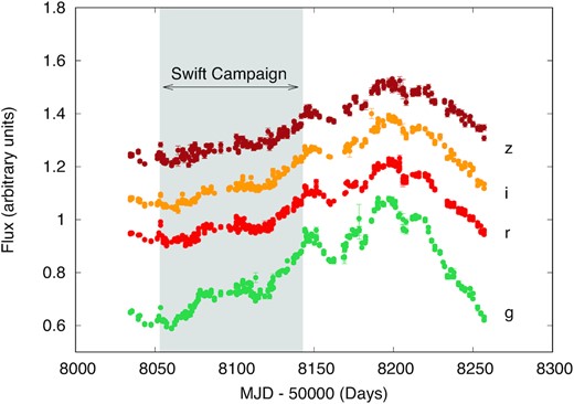
LCO + LT observations of Mrk 110 using griz filters. Light curves were computed with respect to their mean, and shifted vertically for clarity. The grey area shows the strictly simultaneous coverage with Swift observations.
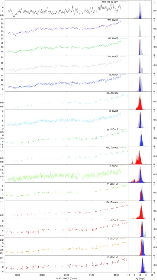
Left-hand panels: Light curves used for the short time-scale lag analysis. While the XRT light curve is shown in count s−1, the measurements in the UVOT filters are in (×10−15) erg cm−2 s−1 Å−1. Regarding the ground-based observations, LCO + LT is in (×10−15) erg cm−2 s−1 Å−1, while RGB Zowada light curves are in arbitrary units. Right-hand panels: Lag versus UVW2 band probability distribution using unfiltered light curve (grey), and filtered ones by removing the linear trend (red) and a 10-d box-car moving average (blue).
Report of the observations. Columns 1 and 2 report telescope and filter, respectively, 3 and 4 show the start and end of the light curve in MJD. Column 5 reports the number visits during the whole campaign. The average, minimum, and maximum flux (in units of count rate for XRT, and (×10−15) erg cm−2 s−1 Å−1 for the other filters) during the period of strict simultaneity of all observatories (i.e. MJD 58053–58143) are reported in column 6, 7, and 8. Column 9 reports the number of points during the XRT campaign.
| (MJD 58053–58143) | ||||||||
|---|---|---|---|---|---|---|---|---|
| Telescope | Filter | Start | End | No. Visits | Avg. | Min. | Max. | No. Visits |
| XRT | 0.3–10 keV | 58053.1 | 58143.9 | 253 | 1.24 ± 0.23 | 0.66 | 1.89 | 253 |
| UVOT | UVW2 | 58053.1 | 58143.9 | 226 | 23 ± 4 | 14.75 | 33 | 226 |
| – | UVM2 | 58053.1 | 58143.9 | 224 | 20 ± 3 | 13.6 | 26.8 | 224 |
| – | UVW1 | 58053.1 | 58143.9 | 233 | 17 ± 2 | 12.6 | 22.7 | 233 |
| – | U | 58053.1 | 58143.9 | 243 | 11.1 ± 1 | 8.6 | 13.7 | 243 |
| – | B | 58053.1 | 58143.9 | 244 | 6 ± 0.5 | 4.9 | 7.5 | 244 |
| – | V | 58053.1 | 58143.9 | 243 | 4.5 ± 0.6 | 3.8 | 5.4 | 243 |
| Zowada | Bz | 58033.5 | 58208.2 | 74 | 1 | 0.77 | 1.07 | 34 |
| – | Gz | 58028.5 | 58197.2 | 73 | 1 | 0.81 | 1.06 | 36 |
| – | Rz | 58028.5 | 58208.2 | 91 | 1 | 0.9 | 1.04 | 37 |
| LCO + LT | g | 58034.4 | 58257 | 309 | 5.8 ± 0.6 | 4.6 | 6.4 | 156 |
| – | V | 58034.4 | 58248.2 | 170 | 4.5 ± 0.6 | 3.7 | 5.6 | 80 |
| – | r | 58034.4 | 58257 | 435 | 5.4 ± 0.5 | 4.7 | 5.7 | 238 |
| – | i | 58034.4 | 58257 | 286 | 2.8 ± 0.3 | 2.4 | 3.1 | 154 |
| – | z | 58034.4 | 58257 | 280 | 2.2 ± 0.1 | 1.9 | 2.3 | 150 |
2.1 Swift
Swift observed Mrk 110 three times per day from 2017 October 26 to 2018 January 25. Each observation totalled approximately 1 ks although observations were often split into two, or sometimes more, visits. The Swift X-ray observations were made by the X-ray Telescope (XRT; Burrows et al. 2005) and UV and optical observations were made by the UV and Optical Telescope (UVOT; Roming et al. 2005). In total, 253 visits satisfying standard good time criteria, such as rejecting data when the source was located on known bad pixels (e.g. see https://Swift.gsfc.nasa.gov/analysis/xrt_swguide_v1_2.pdf), were made. The XRT observations were carried out in photon-counting (PC) mode and the UVOT observations were carried out in image mode. X-ray light curves in a variety of energy bands were produced using the Leicester Swift Analysis system (Evans et al. 2007). We made flux measurements for each visit, i.e. ‘snapshot’ binning, thus providing the best available time resolution. X-ray data are corrected for the effects of vignetting and aperture losses.
During each X-ray observation, measurements were made in all six UVOT filters using the 0x30ed mode that provides exposure ratios, for the UVW2, UVM2, UVW1, U, B, and V bands of 4:3:2:1:1:1. UVOT light curves with the same time resolution were made using a system developed by Gelbord et al. (2015). This system includes a detailed comparison of UVOT ‘drop out’ regions, as first discussed in observations of NGC 5548 (Edelson et al. 2015). When the target source is located in such regions the UVW2 count rate is typically 10–15 per cent lower than in other parts of the detector. The drop in count rate is wavelength dependent, being greatest in the UVW2 band and least in the V-band. The new drop-out box regions are based on intensive Swift observations of three AGNs, i.e. NGC 5548 (Edelson et al. 2015), NGC 4151 (Edelson et al. 2017), and NGC 4593 (McHardy et al. 2018). Observations falling in drop-out regions were rejected.
The resultant Swift light curves, together with ground-based observations described below (Section 2.2), are shown in Fig. 2. As observed previously (Bischoff & Kollatschny 1999; Kollatschny et al. 2001), Mrk 110 varied significantly in all bands during these observations (see Fvar in Table 2).
Results of the lag versus UVW2 band computed between different bands. For sake of completeness, we reported even the lags with multiple peaks, even though they are probably due to artefacts.
| Band | Wavelength (Å) | Fvar (per cent) | peak r | Lag FRRS (d) | peak r | Lag FRRS (d) | peak r | Lag FRRS (d) | Lag Javelin (d) |
|---|---|---|---|---|---|---|---|---|---|
| (Linear) | (Box-car) | (un-filtered) | |||||||
| X-ray | 0.25 | 17.6 | 0.29 ± 0.05 | −0.03|$_{-0.12}^{+0.53}$| | 0.38 ± 0.05 | 0.15|$_{-0.17}^{+0.37}$| | 0.65 ± 0.09 | −0.13|$_{-2.47}^{+0.88}$| | −0.17|$_{-0.04}^{+0.3}$| |
| UVW2 | 1928 | 15.3 | – | – | – | – | – | – | – |
| UVM2 | 2246 | 13.8 | 0.88 ± 0.02 | −0.14|$_{-0.11}^{+0.39}$| | 0.77 ± 0.03 | 0.03|$_{-0.13}^{+0.15}$| | 0.98 ± 0.01 | 0.56|$_{-0.56}^{+1.19}$| | 0.01|$_{-0.01}^{+0.03}$| |
| UVW1 | 2600 | 11.5 | 0.86 ± 0.02 | −0.05|$_{-0.15}^{+0.25}$| | 0.72 ± 0.04 | 0.04|$_{-0.12}^{+0.18}$| | 0.97 ± 0.01 | 0.62|$_{-0.67}^{+1.63}$| | 0.01|$_{-0.02}^{+0.05}$| |
| U | 3465 | 10.8 | 0.72 ± 0.03 | −0.01|$_{-0.29}^{+0.41}$| | 0.57 ± 0.04 | 0.14|$_{-0.24}^{+0.26}$| | 0.95 ± 0.01 | 0.45|$_{-0.85}^{+1.10}$| | 0.03|$_{-0.16}^{+0.18}$| |
| B | 4392 | 8.2 | 0.68 ± 0.04 | 0.69|$_{-0.33}^{+0.37}$| | 0.523 ± 0.05 | 0.66|$_{-0.28}^{+0.62}$| | 0.93 ± 0.01 | 0.84|$_{-0.96}^{+1.04}$| | 0.31|$_{-0.38}^{+0.32}$| |
| Bz | 4500 | – | 0.68 ± 0.04 | 0.03|$_{-0.78}^{+1.02}$| | – | – | 0.93 ± 0.01 | |$0.31_{-1.16}^{+1.34}$| | – |
| Gz | 5500 | – | 0.68 ± 0.04 | −0.22|$_{-1.33}^{+0.97}$| | – | – | 0.93 ± 0.01 | −0.71|$_{-0.59}^{+1.01}$| | – |
| Rz | 6500 | – | 0.55 ± 0.05 | 0.99|$_{-1.34}^{+0.76}$| | – | – | 0.94 ± 0.01 | 1.14|$_{-1.09}^{+1.36}$| | – |
| g | 4770 | 14.1 | 0.7 ± 0.1 | 1.04|$_{-0.24}^{+0.31}$| | 0.42 ± 0.11 | 1.46|$_{-0.56}^{+1.04}$| | 0.93 ± 0.03 | 0.87|$_{-0.47}^{+1.03}$| | 1.02|$_{-0.09}^{+0.07}$| |
| V | 5468 | 12.7 | 0.78 ± 0.03 | 0.96|$_{-0.4}^{+0.5}$| | 0.53 ± 0.06 | 1.75|$_{-0.35}^{+0.6}$| | 0.97 ± 0.01 | 2.05|$_{-0.80}^{+0.85}$| | 2.16|$_{-0.05}^{+0.84}$| |
| r | 6400 | 9.4 | 0.55 ± 0.05 | |$1.54_{-0.39}^{+0.51}$| | 0.5 ± 0.05 | 2.30|$_{-0.32}^{+0.44}$| | 0.94 ± 0.01 | 2.79|$_{-1.49}^{+1.27}$| | 3.04|$_{-0.54}^{+0.03}$| |
| i | 7625 | 10.7 | 0.54 ± 0.05 | 1.50|$_{-0.40}^{+0.75}$| | 0.42 ± 0.05 | 2.72|$_{-0.42}^{+0.63}$| | 0.91 ± 0.01 | 2.69|$_{-0.69}^{+0.86}$| | 2.29|$_{-0.18}^{+0.52}$| |
| z | 9132 | 9.4 | 0.51 ± 0.05 | 2.40|$_{-0.50}^{+1.05}$| | 0.46 ± 0.06 | 2.39|$_{-0.44}^{+0.76}$| | 0.91 ± 0.01 | 2.66|$_{-0.96}^{+1.74}$| | 2.09|$_{-0.04}^{+0.06}$| |
Lag versus g band using the smoothed light curves: i.e. after applying a 10 d box-car moving average. Values are plotted in Fig. 5, bottom panels.
| Band | Lag (d) |
|---|---|
| BAT | −9.43 |$_{-1.27}^{+1.53}$| |
| V | 0.28|$_{-0.78}^{+1.57}$| |
| r | 2.40|$_{-0.78}^{+0.55}$| |
| i | 3.94|$_{-0.59}^{+0.76}$| |
| z | 8.01|$_{-0.70}^{+1.10}$| |
| Band | Lag (d) |
|---|---|
| BAT | −9.43 |$_{-1.27}^{+1.53}$| |
| V | 0.28|$_{-0.78}^{+1.57}$| |
| r | 2.40|$_{-0.78}^{+0.55}$| |
| i | 3.94|$_{-0.59}^{+0.76}$| |
| z | 8.01|$_{-0.70}^{+1.10}$| |
2.2 Ground-based observations
Ground-based observations were performed with almost daily cadence between 2017 October and 2018 May 19 at LCO, the LT, and Zowada Observatory. Table 1 lists the start and end dates and number of visits for each filter.
Las Cumbres Observatory: We used the 1-m robotic telescopes of the LCO network (Brown et al. 2013) and Sinistro imaging cameras to observe Mrk 110.1 Observations were taken in Johnson V, SDSS g′r′i′, and Pan-STARRS zs filters (abbreviated hereinafter as griz for convenience). Exposure times were typically 2 × 300 in the V and z bands, and 2 × 180 s in g, r, and i.
Liverpool Telescope: Observations were carried out at the 2-m LT (Steele et al. 2004) using the IO:O imaging camera and griz filters. Exposure times were 2 × 10 s in each filter.
Zowada Observatory: The Zowada Observatory, located in New Mexico, operates a 20-inch robotic telescope.2 During the Mrk 110 campaign, it was in its full first season of operations and was equipped with RGB astrophotography filters having effective wavelengths of 6365 Å, 5318 Å, and 4519 Å, respectively; these will be listed as Rz, Gz, and Bz to distinguish them from other filter systems. Typically seven exposures of 100 s were obtained per filter on each visit.
2.3 Ground-based light-curve measurements
All images were processed with standard methods as part of the observatory pipelines, including overscan subtraction, flat-fielding, and world coordinate system solution. Measurement of light curves from the LCO and LT data was carried out using the automated aperture photometry pipeline described by Pei et al. (2014). This procedure, written in IDL, is based on the photometry routines in the IDL Astronomy User’s Library (Landsman 1993). The routine automatically identifies the AGN and a set of comparison stars in each image by their coordinates and carries out aperture photometry in magnitudes. An aperture radius of 4 arcsec was used, along with a background sky annulus spanning 10–20 arcsec. The comparison star data are then used to normalize the magnitude scale of each image to a common scale. For Mrk 110, 10 comparison stars were used. Measurements taken at a given telescope on the same night were averaged together to produce a single data point.
Photometric uncertainties include the statistical uncertainties from photon counts and background noise, and an additional systematic term determined by measurement of the excess variance of the comparison star light curves after normalization. The systematic term, measured separately for each telescope and each filter, accounts for additional error sources such as flat-fielding errors or point-spread function variations across the field of view. The uncertainties on each data point were combined as |$\sigma ^2_\mathrm{total} = \sigma ^2_\mathrm{stat} + \sigma ^2_\mathrm{sys}$|.
To account for small calibration differences between the telescopes, the LT light curves were shifted by adding a constant offset in magnitudes to bring them into best overall agreement with the LCO data. The magnitude scale for each filter was calibrated using comparison star magnitudes taken from the APASS catalogue (Henden et al. 2012). Finally, the light curves were converted from magnitudes to flux density (fλ).
For the Zowada data, aperture photometry was performed using a circular aperture of radius 4 pixels (5.7 arcsec) on Mrk 110 and three nearby comparison stars. The mean seeing FWHM was approximately 2.3 pixels. The comparison stars were between 1 and 3 times brighter than Mrk 110. Relative photometry was calculated from individual exposures, and the mean of all exposures for a given night used to create the AGN light curve in each filter. Since standard star calibrations are not readily available for the Zowada filter passbands, the flux scale of the Zowada light curves is not calibrated to an absolute scale. Without a flux calibration, the Zowada data can still be used for lag measurements but not for measurement of the AGN spectral energy distribution.
3 ANALYSIS
3.1 Variability: intraband variability and lags
3.1.1 X-ray versus UVW2 correlation
As a first step, we quantified the correlation between the X-ray and UVW2 bands. We show in Fig. 3 the discrete correlation function (DCF; Edelson & Krolik 1988) between these two bands, together with simulation-based confidence contours (Breedt et al. 2009). We see that a correlation exists between these two bands at a confidence level greater than 99 per cent. No filtering has been applied to the light curves to remove long-term trends which often distort DCFs. Here, the significance level of these contours is reduced, following the method outlined in McHardy et al. (2018), to take account of the range over which lags are investigated. The present light-curve simulation method follows Emmanoulopoulos, McHardy & Papadakis (2013), with code available from Connolly (2015), which takes account of the count rate probability density function as well as the power spectrum of the driving light curve, unlike the method of Timmer & Koenig (1995) which can only produce Gaussian distributed light curves. The present X-ray light curve is not of sufficient quality to determine the shape of the power spectrum; we therefore fixed the broken power-law spectral parameters at those derived by Summons et al. (2008) from combined RXTE and XMM–Newton observations (i.e. αlow = 1, αhigh = 2.8 and νbend = 1.7 × 10⁻⁶ Hz). The level of the confidence contours does not depend greatly on the exact choice of these parameters and, for any reasonable choice, the peak of the DCF always exceeds the 95 per cent confidence level and usually exceeds the 99 per cent level.
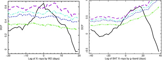
Left-hand Panel: Discrete cross-correlation function (DCF) between XRT (0.3–10 keV) and UVOT (UVW2) light curve . Green, Blue, cyan, and magenta line corresponding to 68, 90, 95, and 99 per cent confidence contours. Right-hand Panel: DCF computed with the smoothed light curves (averaged with a 10 d box-car filter) from BAT (15–50 keV) and g band .
3.1.2 Short time-scales
Given the presence of a significant correlation between the X-ray and the UV band, we evaluated the lag as a function of wavelength with respect to the UVW2 band (1928 Å). As mentioned above, the light curves show clear evidence of a long trend over the whole duration of the campaign, which could affect the measured lag (White & Peterson 1994; Welsh 1999). We therefore performed the calculation by separating short and long time-scales. The canonical approach to study the variability at different time-scales consists of using Fourier domain analysis techniques (Vaughan et al. 2003; Uttley et al. 2014). However, due to the structure of the data, such methods cannot be applied. We therefore filtered out the long-term trend applying two different approaches: in one case we subtracted a linear trend fitted between MJD 58050 and 58150 for the Swift data and MJD 58050 and 58200 (i.e. when the peak of the light curve is reached) for the ground-based data; in the second case, following the procedure used in by McHardy et al. (2014, 2018) we subtracted a moving averaged trend, with a box-car width of 10 d (see also Pahari et al. 2020). The second method is equivalent to evaluating the lag between the two signals after applying a ‘sinc’ filter to their power spectrum, i.e. removing variability longer than 10 d (van der Klis 1989). In particular, we chose a 10 d width due to the presence of few day gaps in the data. It is important to recall that applying the same filter to all light curves prevents the distortion of the lags. We notice that the measured lags remained stable for reasonably small variations of the box-car’s width (i.e. a few days).
In order to compute the lags, we used the so-called flux randomization (FR) and random subset selection (RSS) method (Peterson et al. 1998, 2004). This method evaluates the lag distribution of the interpolated cross-correlation functions (ICCF) by re-sampling and randomizing the values of the fluxes at different epochs N times. Given the structure of the data, we limited the range of the possible lags between −10 and +10 d.
In Fig. 2, we show the ICCF’s centroid probability distributions for the unfiltered and the two filtered (box-car and linearly de-trended) light curves in all the bands. Given the small number of visits (and therefore the large gaps between the points), we did not apply a box-car filter to the Zowada data. The plots show that the distributions obtained from the raw light curves are wider and often distorted; moreover, it is also possible to see that the distributions computed with the linear de-trending method show almost always a shorter central lag. The resulting lag-spectra are shown in Fig. 4, while the results for each band are reported in Table 2. The trends show a clear evolution as a function of wavelength, especially beyond 4000 Å. The values obtained between the two methods are consistent within the errors and at longer wavelength are smaller than the ones obtained in the non-filtered case, suggesting the presence of a time-scale-dependent time-lag.
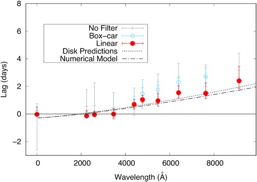
Lag versus UVW2 band spectrum between MJD 58053 and 58143 using XRT, UVOT, and LCO + LT data. For the grey points, the lag was computed from the raw data, while for the full red and empty blue points data were filtered using linear interpolation and a box-car filter, respectively. Dotted and dot–dashed curves represent disc lag analytical and numerical predictions, respectively.
In order to check the consistency of our result, we also computed the wavelength dependent lag using the javelin algorithm (Zu, Kochanek & Peterson 2011), which has been recently shown to produce more realistic errors with respect to the FRRSS method (Edelson et al. 2019; Yu et al. 2020). javelin assumes that the different light curves can be described as a damped random-walk (Zu et al. 2013) linked by an impulse response function: therefore the lag is computed by constraining the parameters of the process and of the impulse response function through a Markov chain Monte Carlo. The results for the raw light curve are shown in Table 2, and are fully consistent with the results obtained with the FRRSS.
To better characterize the variability properties of the light curve, we also quantified the excess variance in each band and also their correlation coefficient with respect to the UVW2 band. As already seen in other AGN studies, the source showed a very strong correlation between the UVW2 and the longer wavelengths bands (all ≥ 0.9) and poorer correlation with the X-rays. Repeating the same experiment using the filtered light curve, however, we notice two interesting features: first, the X-ray-UVW2 correlation becomes significantly poorer (0.29) and second, the correlation seems to decrease as a function of wavelength. For the X-rays such a drop in correlation can be explained by the presence of much stronger fast variability in the X-rays (excess variance is almost 18 per cent). On the other hand, at longer wavelength the poorer correlation is due to the decreasing variability at longer wavelengths (see Table 1).
3.1.3 Long time-scales
We analysed the overall variability during the campaign. In order to better appreciate the long-term trend, we smoothed the data with a moving average with a box-car filter of 10 d width. Due to the different sampling strategies of the various telescopes, we combined the light curves with similar filters. In particular, we merged the V band data from UVOT and LCO + LT and the r band data from LCO + LT together with the Rz band from the Zowada observatory. To do this, we used the inter-calibration software cali (Li et al. 2014). Given that the Zowada Rz band is computed with respect to the average, calibration was done in two steps: first, the r band was also renormalized with respect to its average before running the software, then the resulting light curve was multiplied by the average r band flux.
The ground-based light curves in the 4000 to 10 000 Å regime show a clear increase as a function of time reaching a peak around MJD 58200. However, XRT and UVOT covers only the first section of the light curve (see Table 1, Figs 1 and 2). In order to cover also the peak of the light curve at higher energies we downloaded the BAT daily light curve from Krimm et al. (2013) from its online archive.3 BAT light curves are known to show spurious variations due to the large field of view used with coded-mask technology. Even though the source detection is not significant at a 5σ level, the variations observed in the data are present on time scales longer than ≈ a few days, and are not correlated with variations in the Crab or other nearby sources.
Given the low statistics of the data, we applied a 10-d box-car filter to smooth the light curve. In order to be able to compare properly its behaviour with the other filters, we applied the same procedure to the ground-based ones. As shown in Fig. 5, a clear peak in the 15–50 keV band is seen at approximately MJD 58180. Given the strong resemblance between the BAT and the optical light curve, we conclude that the observed flare is most probably due to an intrinsic variation of the source and not a systematic effect. Moreover, it is clear that while the rise of the BAT is significantly faster than the one observed at lower energy, the optical bands seem to decay with a slower rate as a function of wavelength.
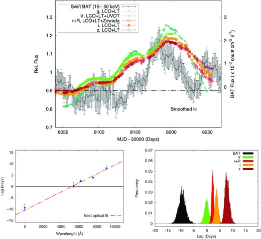
Top Panel: Light curves used for the long-term trend analysis. Bottom-Left Panel: Lag versus wavelength plot using long time scales. Bottom-Right Panel: Lag distributions from which the lag spectrum was obtained.
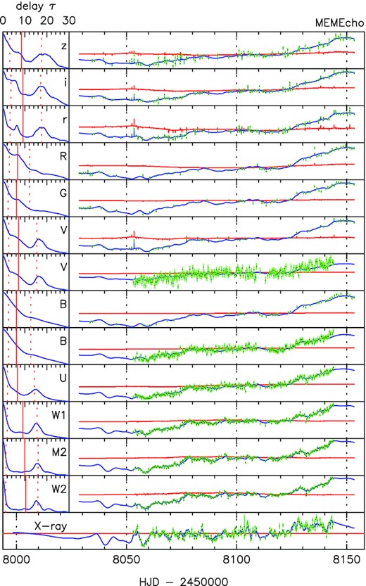
Results from the MEMEcho modelling. Left-hand Panels: Inferred response functions to be applied to the X-ray band in order to reconstruct the light curves at lower energies. Right-hand panels: Observed (green points) and modelled light curves (blue line).
As in the previous section, we computed the DCF to quantify the correlation between the BAT and the g band, including the data between MJD 58140 and 58240. Sensibly small changes (≈few days) in the choice of the dates and of the box-car width did not lead to any significant differences in our results. Confidence contours were derived in the same way as described in the previous section. Although the exact lag is not well defined by this simple DCF, the peak is around a lag of about 15 d and is significant at just below the 99 per cent confidence level (Fig. 3).
In particular, we use the same power spectral parameters to synthesize BAT light curves as are quoted for the earlier XRT light curve. Both BAT and long-term g-band have here been smoothed, which will remove high-frequency variability and should steepen the power spectrum. The power spectrum for the smoothed BAT light curve is reasonably well fitted by a single power law of slope −1.5 but the bend frequency derived by the method of Summons et al. (2008) is within the range of the power spectrum so a model changing slope from −1 at low frequencies to −2.8 at higher frequencies could also be fitted. We have tried a variety of different underlying BAT power spectral shapes and the peak significance reaches the 99 per cent confidence level.
We then computed the lags as function of wavelength with the FRRS method by using the 10-d smoothed light curves, and choosing the g filter as reference band. The lag probability distributions are shown in Fig. 5 (bottom right panel). As expected the g is lagging behind the BAT curve by ≈10 d. The lag increases as function of wavelength, going from few days in the V band to almost 10 d for the g versus z band (see Table 3 and Fig. 5, bottom panels). Given the shape of the light curves, it is clear that the origin of the measured delay is the slower response of the longer wavelength during the decay after the peak. However, it is interesting to notice that the lag spectrum for the long time-scales seems to follow a linear trend from X-ray to near-IR (see Fig. 5). We also tested the goodness of the lag by changing the width of the box-car, finding a stable lag between 5 and 13 d. For shorter width, the statistics becomes too low to measure a significant lag; for larger box-cars, the long-term trend is distorted by the smoothing, changing the value of the lag.
3.2 Reverberation modelling
As a first unbiased approach, we attempted to model and reproduce the variable emission from an X-ray corona illuminating the accretion disc through the MEMECHO algorithm (Fig. 6, see Horne 1994) using all the collected light curves: i.e. attempting to reconstruct the impulse response function of the system through a maximum-entropy solution method (see also McHardy et al. 2018). We chose the X-rays as a reference band. The algorithm manages to reconstruct the light curve at lower energies, with an acceptable chi square (χ2/N = 1.1). The obtained responses show clearly a broadening as a function of wavelength. However, it is also interesting to notice that almost all responses (especially at longer wavelengths) require a long tail that extends to ≈ 10–20 d, as seen also by the lag computed by using the long-term light curve. The excesses shown around 20 light d in the response of some filters are likely due to the presence of an X-ray dip around MJD 58060. The modelling using the UVW2 filter as a reference band showed a smoother trend. Nevertheless, the consistency of the shape of the response function among the different filters indicates that the presence of an extra component acting at longer time-scales.
We then performed a more detailed modelling using the same numerical code used by McHardy et al. (2018). This model computes the response function of a Shakura & Sunyaev (1973) accretion disc illuminated by a ‘lamp-post’ X-ray source (i.e. a point-source located over the rotation axis of the disc at a certain height). The expected lag is taken as half the time for the total light to be received. We considered a mass of 2 × 10⁷ M⊙ (Bentz & Katz 2015), an accretion rate of L/LEdd = 40 per cent (Meyer-Hofmeister & Meyer 2011), a source height of 6 gravitational radii (RG), and an inclination of 45°.4 As shown in Fig. 4, even though the data points at shorter wavelengths seem to present a flatter trend, the predicted lag is in good agreement with the observations.
3.3 Spectral energy distribution and energetics
3.3.1 Flux–flux analysis
Where X(t) is a dimensionless light curve with a mean of 0 and standard deviation of 1. Aλ(λ) is a constant for each light curve, and Rλ(λ) is the rms spectrum. All three parameters are determined by the fit. Such a simplified model does not take account of any time lags, adding some scatter around the linear flux–flux relations. We first focused using the rise of the light curve during which all the facilities were observing. The results of the fit are shown in Fig. 7. We estimate the minimum host galaxy contribution in each band by extrapolating the best-fitting relations to where the first band crosses fλ = 0. The constant spectrum is consistent with the past host galaxy measurements by Sakata et al. (2010). The rms spectrum follows a λFλ ≈ λ−4/3, as expected from the predictions of an accretion disc.
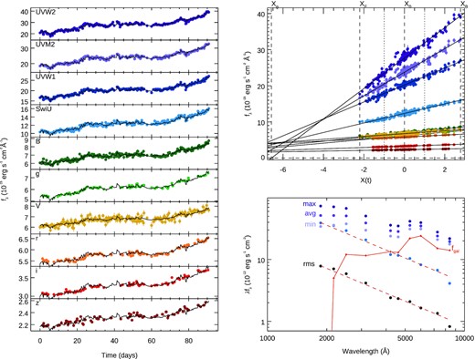
Flux–flux analysis for the rising section of the light curve. Left-hand panels show the light curves, and the model (black line). The parametrization described in equation (2) represents the data well. Top right panel shows the flux–flux relation between the different bands and the driving light curve X(t). Bottom right panel shows the optical/UV variable spectrum. Purple points on the higher section of the graph represent, minimum, average, and maximum values for each band. Orange continuous line represents the host galaxy contribution. Blue points show the rms spectrum computed as maximum–minimum, while the black point represents the actual rms. Red dashed lines show the best fit.
We then analysed the long-term trend using the ground-based data. When plotting the modelled light curve with respect to the real observations, only the rise is well reproduced, while of the decay follows a different trend (see Fig. 8, top panels). We therefore analysed the tail of the long-term variation separately (see Fig. 8, bottom panels), finding a significantly steeper spectrum (λFλ ≈ λ−2). The presence of a variable component different from a standard accretion disc can explain the presence of a longer lag at longer time-scales.
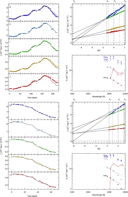
The two blocks show the flux–flux analysis for the whole light curve (Top) and only the tail (bottom). Left-hand panels show the light curves, and the model (black line). A hysteresis is evident while using the whole light curve. Top right panels show the flux–flux relation between the different bands and the driving light curve X(t). Bottom right panels show the optical/UV variable spectrum. Purple points on the higher section of the graph represents, maximum, average, and maximum values for each band. Orange continuous line represents the galactic contribution. Blue points show the rms spectrum computed as maximum–minimum, while the black point represents the actual rms. Red dashed lines show λfλ ∝ λ−4/3.
3.3.2 SED: optical-UV/X-ray broad-band
The analysis reported so far shows the presence of a clear connection between the X-ray and optical-UV variability, but does not take into account the energy budget of the two components. In order to quantify it, we estimated the variable flux in the different bands. We therefore built the X-ray spectral energy distribution from the XRT data including also the Mrk 110 BAT 70 month catalogue spectrum. The flux in the 14–195 keV range is 5.7 × 10⁻¹¹ erg cm−2 s−1 with a power-law slope (Γ) of 2. The XRT data (0.3–10 keV), instead, shows a harder slope (Γ3 − 5keV = 1.66 ± 0.07; see Fig. 9, right-hand panel). This has already been seen in past studies (Idogaki et al. 2018) and suggests the presence of the so-called Compton hump (see e.g. Guilbert & Rees 1988; Lightman & White 1988; George & Fabian 1991). We therefore applied a simple model for an exponentially cut-off power-law spectrum, reflected by neutral material (i.e. pexrav; Magdziarz & Zdziarski 1995). We grouped the XRT spectrum with a minimum of 30 counts per bin using the FTOOL grppha. We included in the fit a broad line for Kα and the blackbody emission for the soft excess. The results are reported in Table 4 under Model 1. We obtained a fit with χ2 of 439 (375 degrees of freedom). The model finds a power-law slope of Γ ≈ 1.66 ± 0.02 with a cut-off at ≈ 120 keV and reflection fraction of 0.2. In order to estimate the total ionizing flux, we extrapolated the power-law flux in the 3–5 keV band to the 0.1–150 keV range: we obtained Fpl = 1 × 10⁻¹⁰ erg s−1 cm−2.
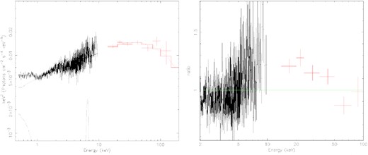
Left-hand Panel: X-ray emission spectrum observed by Swift XRT (black points) and BAT (red points) and modelled with Model 1. Right-hand Panel: Ratio of the data to a simple power-law model.
Best-fitting parameters modelling. Model 1 was applied to the only X-ray data from XRT + BAT and is consists in zphabs × [pexrav+zgauss+zbbody]. Errors are reported with 90 % confidence interval contour. In order to obtain the fit, we froze the following parameters: nH = 1.27 × 10²⁰ [cm−2], z = 0.035; He abund (elements heavier than He) = 1; Fe abund = 1. Model 2 includes also optical and UV wavelength, and was parametrized with using zphabs × optxagnf. Mass was fixed to 2 × 10⁷M⊙, accretion rate to 40 |$\mathrm{ per\,cent}$|, Rout = 103 RG, spin a to 0.
| Model 1 | Model 2 | ||||
|---|---|---|---|---|---|
| zphabs × [pexrav+zgauss+zbbody] | zphabs × optxagnf | ||||
| Parameter | Best Fit | Parameter | Best Fit | ||
| Γ | 1.66 ± 0.02 | Γ | 1.72 ± 0.02 | ||
| Ecut [keV] | 118|$_{-22}^{+33}$| | a | 0 | ||
| reflfrac | 0.21|$_{-15}^{+0.17}$| | Rcor [RG] | 70 ± 20 | ||
| normpexrav (× 10−3) | 5.2 ± 0.1 | kTe [keV] | 0.25 ± 0.08 | ||
| LineE [keV] | 6.7 ± 0.1 | τ | 11 ± 2 | ||
| σE [keV] | 0.3|$_{-0.2}^{+0.8}$| | fpow | 0.5 ± 0.1 | ||
| normzgauss (× 10−5) | 4.2 ± 0.1 | ||||
| kT [keV] | 0.11 ± 0.05 | ||||
| normzbbody (× 10−5) | 5.62 ± 0.4 | ||||
| χ2/ d.of. | 648 / 590 | χ2 / d.of. | 769/594 |
In order to quantify the connection with the optical-UV emitting component, it is necessary to take into account the illuminating fraction. Following the assumptions described in the previous section, we estimate that total amount of radiation impacting the disc is 3 × 10⁻¹¹ erg s−1 cm−2. Moreover, given that the source can vary up to 1 count s−1 the variable flux we can take as an upper limit to the variable flux ≈2 × 10⁻¹¹ erg s−1 cm−2.
From the rms-spectrum computed in the previous subsection, we obtained a variable optical-UV flux of 2.5 × 10⁻¹¹ erg s−1 cm−2. We conclude therefore that the X-ray variations contain enough energy to power most of the variability seen in the optical-UV (if they are driven by an illuminated accretion disc). We also notice that if the low-energy emission is dominated by the BLR, the solid angle to which it is exposed will be much larger, and the argument will still be valid.
The reported estimate for the ionizing variable flux sets a solid lower limit, which, however, is based on a purely phenomenological model. In order to have a more realistic value, we also fitted the SED using the physically motivated model optxagnf (Done et al. 2012). The model assumes the presence of emission from an extended hot corona, going from the soft X-rays to the far-UV, while optical and near UV emission would be dominated by the accretion disc.
We included optical and UV data average fluxes, subtracting the galactic contribution. The fit was performed by fixing mass accretion rate L/LEdd = 40 |${{\ \rm per\ cent}}$| and spin (a) to 0. Mass, redshift, and distance were fixed accordingly to values reported in the introduction. The best-fitting model reproduced the data with an acceptable chi square (χ2 / d.o.f = 769 / 594; see Table 4). Some excess is found at higher energies and in the UVOT band. This means that the flux will be slightly overestimated. We also attempted to fit the data with a = 0.998, but, despite values were still in the same range of uncertainties of the previous fit, the obtained χ2 was significantly worse (χ2/d.o.f.≈2). However, an acceptable χ2 was found for a mass of 2.5 × 10⁷M⊙ (which is still within the range of uncertainties for most f-factors; Bentz & Katz 2015). We estimated a total ionizing flux (5 eV–1000 keV) of Fion ≈ 6 × 10⁻¹⁰ erg cm−2 s−1 (i.e. Lion ≈ 7 × 1045 erg s−1).
3.3.3 HST spectroscopy
The diffuse continuum (DC) emission from the BLR will be a source of wavelength-dependent lags in addition to lags from reprocessing in the accretion disc (Korista & Goad 2001, 2019; Lawther et al. 2018). In order to estimate the contribution from the BLR DC, we obtained Hubble Space Telescope (HST) spectra of Mkn 110. Observations were performed on 2017 December 25, 2018 January 3, and 2018 January 10 using STIS. Observations were taken with the 52 arcsec × 0.2 arcsec aperture using the G230L, G430L, and G750L gratings. During each epoch exposures totally 800s (G230L), 180s (G430L and 180s (G750L) were obtained. In addition to the standard pipeline-processing we used the stis_cti package to apply Charge Transfer Inefficiency corrections to the data. Moreover, we used the contemporaneously obtained fringe flats to defringe the G750L spectra. Any remaining large outliers in the spectrum that were identified visually as hot pixels were removed manually.
We fit the mean spectrum with a variety of models to estimate a plausible contribution from the BLR DC. To model the BLR DC, we use a model calculated by Korista & Goad (2019) that is tailored for NGC 5548. This assumes a locally optimally emitting cloud model for the BLR, with a fixed cloud hydrogen column density of log NH(cm−2) = 23, and a gas density distribution ranging from log nH(cm−3) = 8–12 (solid black line in fig. 4 of Korista & Goad 2019; see that paper for full details of the model calculation). We Doppler-broaden the DC model by convolving with a Gaussian with FWHM = 5000 km s−1 (Peterson et al. 1998, 2004), consistent with emission from the inner BLR in Mrk 110. The presented DC model does not include the unresolved high-order Balmer and Paschen emission lines redward of those jumps. In addition to the pile-up of Doppler-broadened higher-order Balmer, Paschen, and other emission lines (He i and Fe ii), there is another effect that may serve to smooth the free–bound continuum emission jumps in wavelength space. The cloudy photoionization model simulations all assume that the wavelengths of the Balmer and Paschen series limits are at their low-density values, with these values then corrected for atmospheric refraction. However, due to the likely presence of high-density gases within the BLRs of AGN (e.g. 1012–13 cm−3), the wavelengths of the free–bound jumps are likely shifted to somewhat longer wavelengths due to the finite sizes of the emitting hydrogen atoms. The contributions of mixtures of continuum emission from gas spanning the full range of expected densities within the BLR will thus smooth out somewhat the abrupt free–bound continuum jumps in wavelength space. This effect is also currently not included in the model spectral template. As neither of these effects are included in the spectral template for the BLR DC, we exclude the wavelength ranges 3600–4050 Å and 8000–8700 Å from the fit.
We further note that we have not calculated a model specific to the line luminosities of Mkn 110, and, while the general shape of the DC spectrum is common to all models, the amplitudes of the Balmer and Paschen jumps do depend somewhat on model assumptions. For these reasons, we view the present spectral fitting process as simply providing a guide and an estimate of the BLR DC contributions to the spectrum.
For the underlying AGN continuum emission, we try two different models – the first is a simple power law, the second is a standard accretion disc model (Shakura & Sunyaev 1973) with the outer radius set to be equivalent to a temperature of 2000 K. This produces a spectrum following the relation Fλ ∝ λ−7/3 through most of the wavelength range, but begins to rollover at the longest wavelengths. These two models test the sensitivity of the results to assumptions about the accretion disc emission. We include both UV and optical Fe ii templates. In the optical, we use the template of Véron-Cetty et al. (2001), while in the UV we use the model of Mejía-Restrepo et al. (2018). This latter model has the advantage that it covers a broader wavelength range in the UV than other models. We investigate Doppler broadening in these Fe ii emission models by convolving with a Gaussian, and find best fits for FWHM = 3000 km s−1. We fit broad and narrow emissions lines with Gaussians. For the host dust emission from the torus we include a single temperature blackbody with T = 1800 K, while this is simplistic (see e.g. appendix A of Korista & Goad 2019, for a more complex model), longer wavelength coverage is needed to better constrain this component. We also include an 11 Gyr old solar metallicity stellar population model (Bruzual & Charlot 2003), broadened to the resolution of STIS G430L and G750L. We use the surface brightness profile fit parameters of Bentz et al. (2009) to scale the galaxy flux to the slit width (0.2 arcsec) and extraction size (0.36 arcsec) used for these HST data, finding 6.4 × 10⁻¹⁷ erg s−1 cm−2 Å−1 at 5100Å. This is fixed in all the fits.
The DC model described above is fitted including a scale factor allowing it to best-match the data. Although we have not optimized the modelled DC spectrum for the broad emission line spectrum of Mrk 110, we checked that the spectral fit’s scaling of the DC is in line with the model predictions for NGC 5548 by Korista & Goad (2001, 2019). The best-fitting model using an accretion disc is shown in Fig. 10, and generally does a reasonable job of fitting the overall shape of the spectrum from ∼1600–10 000Å.
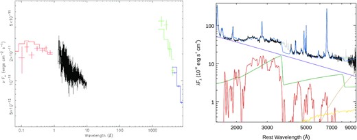
Left-hand Panel: X-ray + optical/UV spectrum of Mrk 110 measure with Swift BAT (red points), XRT (black points), UVOT (green), LCO + LT (blue) data. Data were fitted with Model 2. Right-hand Panel: Mean HST spectrum of Mkn 110 (black). The light grey line shows the wavelength regions excluded from the fit. Blue is the overall model, while individual components shown are the accretion disc (purple), DC (green), Fe ii template (red), stellar population template (yellow), and hot dust blackbody (tan).
We perform synthetic photometry on the best-fitting power-law and disc models to estimate the fraction of the flux contributed by each component in each of the Swift and LCO filters, and they are given in Table 5. Note that the significantly higher spatial resolution of HST compared to Swift and seeing-limited images from the ground mean that Swift and ground-based images will have a significantly higher galaxy fraction in most filters than here. The model with the power-law continuum has shallower slope than the disc, with a best fit of Fλ ∝ λ−2.0. This shallower slope reduces the flux needed from the DC, and both the optical Fe ii and stellar templates, with the normalization of the last two dropping to zero with this model. The contribution from the DC is strongest around the Balmer and Paschen jumps, in the U and i bands, respectively. We estimate it contributes 13–32 per cent of the flux in the U band and 12–30 per cent of the flux in the i band. Moreover, the flux of the Fe ii complex is a significant fraction of the flux throughout the UV, contributing around 20 per cent of the flux in the UVW1 and U bands. If this emission reverberates (as has been reported for optical Fe ii; Barth et al. 2013) then it will also contaminate the accretion disc continuum lags.
Fraction of flux in each of the spectral components through each filter. The first numbers in each column are for the power-law model, the second for the disc model.
| Filter | Power-law or disc | Diffuse continuum | Broad lines | Fe II | All other components |
|---|---|---|---|---|---|
| UVW2 | 0.79, 0.76 | 0.03, 0.08 | 0.11, 0.10 | 0.07, 0.06 | 0.0, 0.0 |
| UVM2 | 0.81, 0.76 | 0.04, 0.11 | 0.025, 0.02 | 0.125, 0.11 | 0.0, 0.0 |
| UVW1 | 0.69, 0.63 | 0.05, 0.14 | 0.05, 0.05 | 0.20, 0.18 | 0.0, 0.0 |
| U (Swift) | 0.64, 0.49 | 0.13, 0.32 | 0.0, 0.0 | 0.22, 0.19 | 0.01, 0.0 |
| B | 0.87, 0.69 | 0.06, 0.16 | 0.06, 0.10 | 0.0, 0.04 | 0.01, 0.01 |
| V | 0.76, 0.54 | 0.08, 0.20 | 0.06, 0.09 | 0.0, 0.07 | 0.10, 0.10 |
| g | 0.77, 0.58 | 0.06, 0.15 | 0.12, 0.18 | 0.0, 0.045 | 0.05, 0.045 |
| r | 0.70, 0.49 | 0.09, 0.24 | 0.15, 0.16 | 0.0, 0.035 | 0.06, 0.075 |
| i | 0.67, 0.42 | 0.12, 0.30 | 0.15, 0.16 | 0.0, 0.01 | 0.06, 0.11 |
4 DISCUSSION
We have investigated the variability of the Seyfert galaxy Mrk 110 with an ≈200 d multiwavelength campaign. We have measured the lags with respect to the UVW2 band for 10 bands from 0.3–10 keV X-rays with the Swift XRT telescope to almost the near-IR. Filtering out the long-term variability (>10 d), we found that the lags increase with wavelength up to ≈ 2.5 d at ≈ 9000 Å. However, below ≈ 4000 Å the lags are very close to zero. On longer time-scales, we do not have coverage with the Swift XRT but there are variations in the hard X-ray band (15–50 keV) detected by the Swift BAT. Here, we find that the g-band lags behind the BAT light curve by ∼10 d and that the other optical bands lag behind the g-band by amounts increasing linearly with wavelength up to almost 10 d for the z-band.
The change of lag behaviour when sampled on different time-scales has been noted previously (McHardy et al. 2018; Chelouche, Pozo Nuñez & Kaspi 2019; Hernández Santisteban et al. 2020; Pahari et al. 2020) and is most simply explained as emission from more than one reprocessor.
4.1 Short time-scales
The increasing continuum lag as a function of wavelength observed on short time-scales is consistent with the expectation from an illuminated disc and has been observed also for other accreting SMBHs (e.g. Wanders et al. 1997; Collier et al. 2001; Shappee et al. 2014; Lira et al. 2015; Edelson et al. 2019; Cackett et al. 2020). However, we highlight here the presence of some interesting features. While for almost all the probed AGN so far, the X-ray to UV lag was always of a few days, (in contradiction with a standard accretion disc predictions; see e.g. Gardner & Done 2017; Cai et al. 2018; Kammoun et al. 2019; Mahmoud, Done & De Marco 2019; Cai, Wang & Sun 2020), we measure a very short and approximately zero lag with respect to the UVW2 band in the range between the X-rays (UVW2-X-ray lag ≈−0.4–1.6 d, 3σ confidence) and near UV (UVW2-UVW1 lag ≈−0.5–0.7 d, 3σ confidence). Even though the measurements are consistent with simulated standard accretion lags (as also found recently by Kammoun, Papadakis & Dovciak 2021a; Kammoun et al. 2021b), we notice that the slope from our best fit is marginally steeper than expected; such a behaviour might therefore suggest the presence of a different radial temperature profile induced by a different accretion flow geometry (Wang & Zhou 1999; Collier et al. 2001; Cackett et al. 2020). This, however, does not seem to be confirmed by the rms spectrum, which shows, during the rise, a power-law slope of ≈ −4/3 during the first part of the campaign.
Moreover, despite a clear feature observed in the HST spectrum, we did not find any significant excess in the U band lag (UVW2-U lag ≈−0.6–1.2 d, 3σ confidence), as often observed in other sources. This excess has been usually associated with the effect of the DC from the BLR (see e.g. Cackett et al. 2018; Lawther et al. 2018; Korista & Goad 2019).
These two elements suggest a fundamental difference between Mrk 110 and the AGN monitored so far. A first possibility could be the higher accretion rate of this source, which can affect the geometry of the accretion flow. Recent observations of other high accretion-rate objects (see e.g. Pahari et al. 2020; Cackett et al. 2020, for NGC 4769 and Mrk 142, respectively), however, still showed evidence of an X-ray-UV and U band excess: therefore, this parameter alone cannot fully explain the observed discrepancies. Another possibility could be the presence of a different component in the UV range, affecting the lag. For instance, the HST spectrum shows a clear strong contribution of the DC and the FeII in the UV, which, however, it is not expected to vary on short time-scales. NGC 7469 and Mrk 142 have a smaller mass with respect to Mrk 110 (see e.g. Peterson et al. 2004; Bentz et al. 2010; Bentz & Katz 2015). Given that the duration of the campaign for these objects is similar, the DC from the BLR could have a stronger contribution to the lags from smaller mass objects, leading to a stronger excess in the UV on short time-scales. This is also supported by the fact that the lags associated with the emission lines from the BLR in NGC 7469 and Mrk 142 are significantly smaller than the ones measured in Mrk 110 (see e.g. Kollatschny et al. 2001; Peterson et al. 2004, 2014; Du et al. 2014). On the other hand, we also notice that the short emission lines observed in Mrk 142 are thought to be due to the shadowing of the BLR by the inner part of the slim disc (Cackett et al. 2020). The lower |$\dot{m}$| of Mrk 110 (hence its more standard disc configuration), may therefore also explain why the lags are longer. A more detailed and systematic comparison between the different sources is therefore necessary to understand how important the relative size of the BLR with respect to the disc is for multiwavelength variability studies.
4.2 Long time-scales
From the analysis of the long-term variations, we observed for the first time a very long lag of ≈ 10 d between the hard X-rays and the g band. The response of the lag seems also to get longer, following the same linear relation, as a function of wavelength. Given the large amount of energy from the hard X-ray flare and the very similar shape between the different bands it is reasonable to believe that the long-term optical variations are indeed powered by the X-rays. However, despite a larger lag is expected on longer time-scales due to the tail in the disc response (Cackett et al. 2007), such long X-ray/optical lags are difficult to explain just in terms of a standard accretion disc. This is also supported by the much steeper slope of the rms spectrum (λFλ ≈ λ−2) detected using the smoothed long-term variations. This indicates the presence of a different physical mechanism for the long-term trend.
Such a long lag could be due to the DC from the BLR. For instance, Mrk 110 is known to have, due to its high luminosity, a large BLR (H β emission line lag behind the continuum of ≈20 light d; Kollatschny et al. 2001; Peterson et al. 2004). This would also be supported by the longer lag as a function of wavelength and by the results of our fit, which shows that the stronger contribution of the DC at longer wavelength. However, other two elements point against a scenario where only the BLR dominates the long term variation: first, during the rise of the long term trend, the flux–flux analysis are fully consistent with the prediction of the accretion disc; second, the HST spectrum shows that the DC can contribute only ≈10–20 per cent of the total emission and variability in the optical (Table 5 and Fig. 10, right-hand panel).
A hint for the solution to such a puzzling behaviour could come from the BAT data. Even though its trend may be affected by the instrument sensitivity, there is a clear difference before and after the peak observed in the hard X-rays. From the light curves and the results of the flux-versus-flux analysis, it is clear that in the first part of the campaign, while the hard X-rays show a very low flux, the optical and UV band follow the same trend; after the rise in the BAT data, instead, the optical bands show a different response as a function of wavelength, leading to the observed linear trend in the lag spectrum.
Large variations in the X-rays are usually associated with changes in the geometry of the system (Done, Gierliński & Kubota 2007; Noda & Done 2018). Spectral timing studies have already shown evidence of the corona changing height on relatively short time-scales in both stellar mass and SMBHs (see e.g. Kara et al. 2019; Alston et al. 2020; Caballero-García et al. 2020). A different size or height of the corona would lead to significant changes in the illuminated regions of the accretion flow. This suggests that the observed behaviour is the result of an interplay between accretion disc reflection and of a second reprocessor that can be the DC from the BLR and/or outer regions of the accretion disc. A detailed modelling of the response of the various components is beyond the aim of this paper; however, it is easy to imagine a scenario in which the relative contribution of this reprocessor to the total emission changes according the geometry of the corona (see Fig. 11).
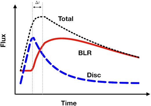
Diagram of the proposed physical scenario for the observed long term trend in the optical bands (black fined-dashed curve), assuming a linear rise and an exponential decay. If we assume that the BAT flare is driven by the disc emission (blue long-dashed curve), then this has a similar rise, an earlier peak (peaks separated by Δt), and a faster decay than the optical bands. Therefore, in order to recover the total light curve, an additional component is needed. We interpret the difference between the total and the disc light curve as the contribution from the DC (red curves), which dominates the emission after the peak.
In particular, it is interesting to notice that the DC from the BLR is expected to have a higher contribution during the decay of the X-ray flare, rather than during the rise, not only because of the light traveltime distance from the central source, but also because of its size. Moreover, the response time of the BLR is known to scale as a function of wavelength due to its ionization stratification (see e.g. Korista & Goad 2001, 2019; Lawther et al. 2018). Therefore, this scenario would explain both the slower evolution of the light curve at longer wavelengths, as well as the linear trend observed in the lag spectrum (see Fig. 11).
An intriguing alternative possibility could be that the change in measured lag is just a consequence of a change in the temperature profile of the disc. Fig. 5 shows clearly that the detection of the lag is due to a slower decline at longer wavelength, while the rise is approximately similar at all bands. A variation lasting a few months, is roughly consistent with the typical disc thermal time-scale of these systems: i.e. the time-scale on which the disc gets back to thermal equilibrium. It is possible to think that after the BAT flare, the temperature profile of the disc might have steepened its radial profile, leading to a variable spectral slope of −2. For instance, Mummery & Balbus (2020) found that an accretion disc extending down to the innermost last stable circular orbit with a finite stress, have a spectrum of λFλ ∝ λ−12/7 ≈ λ−2, so roughly consistent with what we measured. The main consequence of this would be a clear change in the lag spectrum. However, due to the lack of intensive observations during the tail of the flare, this hypothesis cannot be confirmed yet.
New intensive monitoring observations of this source will help to unveil the nature of this behaviour. In particular, these results show the importance of high cadence spectroscopically resolved observations, which is the only way to disentangle the different components present in these systems. Future time resolved and wavelength dependent simulations together with further multiwavelength observations can help to understand the origin of these peculiar behaviours.
5 CONCLUSIONS
We have measured the lag spectrum of the NLS1 galaxy Mrk 110 over a campaign of ≈200 d. Filtering the data on long (>10 d) and short (<10 d) time-scales, we find evidence of different behaviour. On short time-scales, the source shows very short lags that are none the less consistent with the expectations of reprocessing from an accretion disc. On long time-scales, where the Swift BAT provides the X-ray observations, the g-band lags the hard X-rays by ≈ 10 d, with the other optical bands lagging behind the g-band by amounts increasing linearly with wavelength up to almost 10 d for the z-band. The simplest, although not the only possible, explanation of this behaviour is direct continuum radiation resulting from reprocessing in the more distant BLR (Korista & Goad 2019). This behaviour is similar to that seen in NGC 4593 (McHardy et al. 2018). The implied distance to the BLR is longer here than in NGC 4593, but the observed lags are consistent with the ∼20 d lag of the H β line with respect to the continuum (Kollatschny et al. 2001; Peterson et al. 2004). Further, multiband monitoring over long time-scales is necessary to properly reveal the contribution of components other than the accretion disc to the UV and optical variability of AGN.
ACKNOWLEDGEMENTS
The authors thank the referee for the useful comments that improved the quality of paper. FMV and IMH acknowledge support from STFC under grant ST/R000638/1. KH and JVHS acknowledge support from STFC grant ST/R000824/1. The Liverpool Telescope is operated on the island of La Palma by Liverpool John Moores University in the Spanish Observatorio del Roque de los Muchachos of the Instituto de Astrofisica de Canarias with financial support from the UK Science and Technology Facilities Council. This work makes use of observations from the Las Cumbres Observatory global telescope network. Research at UC Irvine was supported by NSF grants AST-1412693andAST-1907290. EMC and JAM acknowledge support for analysis of Zowada Observatory data from the NSF through grant AST-1909199. EMC and JAM acknowledge support for HST program number 15413, which was provided by NASA through a grant from the Space Telescope Science Institute, which is operated by the Association of Universities for Research in Astronomy, Incorporated, under NASA contract NAS5-26555. This work makes use of observations from the Las Cumbres Observatory global telescope network.
DATA AVAILABILITY
Swift raw data can be downloaded from NASA heasarc archive.5 HST raw data can be downloaded MAST website.6 The rest of the ground-based observations cannot be accessed via web, but are available on request to the corresponding author.
Footnotes
Observations were taken under the LCO Key Projects KEY2014A-002 (PI Horne) and KEY2018B-001 (PI Edelson).
An inclination of 40° is usually taken as a standard value for this class of sources (Cackett et al. 2007; Fausnaugh et al. 2016; Kammoun et al. 2019, 2021b). Recent X-ray spectral timing measurements of a similar source have shown evidence of a higher inclination (Alston et al. 2020; see, however, Caballero-García et al. 2020). We notice that while the inclination is known to have a strong effect on the X-ray spectrum, the dependence of the optical lags is expected to be negligible (Cackett et al. 2007; Starkey, Horne & Villforth 2016; Kammoun et al. 2021b).
