


ABSTRACT
We present solutions of force-free pulsar magnetospheres coupled with a uniform external magnetic field aligned with the dipole magnetic moment of the pulsar. The inclusion of the uniform magnetic field has the following consequences: the equatorial current sheet is truncated to a finite length, the fraction of field lines that are open increases, and the open field lines are confined within a cylindrical surface instead of becoming radial. A strong external magnetic field antiparallel to the dipole allows for solutions where the pulsar magnetic field is fully enclosed within an ellipsoidal surface. Configurations of fully enclosed or confined magnetospheres may appear in a double neutron star (DNS) where one of the components is a slowly rotating, strongly magnetized pulsar and the other a weakly magnetized millisecond pulsar. Depending on the geometry, twisted field lines from the millisecond pulsar could form an asymmetric wind. More dramatic consequences could appear closer to merger: there, the neutron star with the weaker magnetic field may undergo a stage where it alternates between an open and a fully enclosed magnetosphere releasing up 1037 erg. Under favourable combinations of magnetic fields DNSs can spend up to 103 yr in the coupled phase, implying a Galactic population of 0.02 systems. Potential observational signatures of this interaction are discussed including the possibility of powering recurring fast radio bursts. We also note that the magnetic interaction cannot have any significant effect on the spin evolution of the two pulsars.
1 INTRODUCTION
The recent discovery of gravitational waves from coalescing neutron stars in the GW 170817 event (Abbott et al. 2017a) has permitted a clear view of this extreme phenomenon across the electromagnetic spectrum (Abbott et al. 2017b). The electromagnetic counterpart observed simultaneously and after the gravitational wave detection has confirmed the predictions of the kilonova model and have set constraints on the formation of a relativistic jet (Metzger et al. 2010; Metzger & Berger 2012; Alexander et al. 2017; Cowperthwaite et al. 2017; Margutti et al. 2017; Nicholl et al. 2017). Even before the merger, though, the magnetospheres of neutron stars will be interacting and modify each other’s structure giving rise to precursor events (Piro 2012; Tsang et al. 2012; Palenzuela et al. 2013; Tsang 2013) possibly associated with radiation received before the prompt emission of a short gamma-ray burst (Troja, Rosswog & Gehrels 2010). The magnetic interaction of the two neutron stars has been simulated for small separations just before the merger takes place (Rezzolla et al. 2011; Etienne, Paschalidis & Shapiro 2012; Paschalidis, Etienne & Shapiro 2013; Ponce et al. 2014). While the interaction of the magnetospheres shortly before and during the merger will definitely be the most dramatic, a window of opportunity of observable effects may occur at earlier times when the two magnetospheres are coupled.
Double neutron stars (DNSs) can form through the recycled pulsar channel (Bhattacharya & van den Heuvel 1991; Tauris et al. 2017). In this scenario the older member of the binary is a millisecond pulsar with a relatively weak magnetic field (∼109 G), whereas the younger one has a magnetic field a few orders of magnitude higher and spins slower. Because of gravitational wave emission their orbit shrinks. It is then possible that the strength of the magnetic field of the younger pulsar at the neighbourhood of the millisecond pulsar to be higher than that of the millisecond pulsar itself. In such a configuration, the magnetosphere of the millisecond pulsar will be drastically modified.
As of now 16 DNS systems and candidates have been identified (Tauris et al. 2017; Stovall et al. 2018). Among them, the double pulsar J0737 − 3039A/B is expected to coalesce in 86 Myr (Stairs 2004). As the two neutron stars move closer they will reach a point where the two magnetospheres interact. Even then, the characteristic length-scales of the system (light cylinders and orbital separation) will still differ by a few orders of magnitude. Because of this, direct numerical simulation may not be the optimal approach. Instead, one could consider the effect of a uniform magnetic field on to a pulsar magnetosphere. In this approach the uniform external field represents the field of the young pulsar that modifies the millisecond pulsar magnetosphere.
The Goldreich & Julian (1969) pulsar model describes the magnetic field configuration of an aligned rotating magnetic dipole. This solution corresponds to a force-free magnetosphere that transitions to a wind at great distances. The magnetosphere contains an equatorial current sheet extending from the light cylinder radius (RLC) to infinity, where poloidal and toroidal electric currents flow. Numerical solutions of the axisymmetric problem postulate the presence of the current sheet on the equatorial plane through the imposed boundary conditions (Contopoulos, Kazanas & Fendt 1999) and then solve for half the volume, either north or south of the equator, taking advantage of the symmetry of the problem. Solutions of the pulsar equation are still feasible if the current sheet continues within the light cylinder. These solutions hold when the open magnetic field lines rotate differentially instead of corotating with the neutron star (Contopoulos 2005; Timokhin 2006). The current sheet in these solutions extends to infinity as well.
Solving the pulsar equation for the entire volume, without imposing any condition on the equatorial plane, leads to a strong, but finite, equatorial current. Indeed, because of the inevitable numerical dissipation of the arithmetic scheme, the formation of infinitesimal current sheets is not feasible (Komissarov 2006). Oblique rotators are even more complicated, not permitting the system to relax to a stationary state. In these systems the field is solved for under the approximation of force-free electrodynamics. Such non-axisymmetric configurations still contain thin currents layers emanating from the light cylinder and extending to large distance from the pulsar (Spitkovsky 2006; Kalapotharakos & Contopoulos 2009; Kalapotharakos, Contopoulos & Kazanas 2012). Beyond the light cylinder the system is dominated by Poynting flux transitioning eventually to a low magnetization hydrodynamical wind (Vlahakis 2004).
The influence of a strong external magnetic field may modify drastically the pulsar magnetosphere and wind. DNSs will affect each other either via winds at large separations or through direct interaction of their magnetospheres once they are close to each other. In a previous paper (Gourgouliatos & Lynden-Bell 2011), we have provided a heuristic description of the magnetic field of a rotating dipole coupled to a uniform external magnetic field. Here, we revisit this problem through exact analytical and numerical solutions. As a key element of the pulsar magnetosphere is its infinite current sheet, we start our discussion from the modification of a current sheet arising by a split monopole, once an external uniform magnetic field is included. This configuration is then used as a guide for the numerical solution of a system where a relativistically rotating dipole magnetic field is embedded inside a uniform magnetic field.
The plan of this paper is as follows. In Section 2, we solve analytically and numerically a model problem of a split monopole embedded in a uniform external field. In Section 3, we solve numerically the pulsar equation embedded in a uniform magnetic field. We present the implications of these solutions to magnetically interacting DNSs in Section 4. We discuss our results in Section 5. We conclude in Section 6.
2 A MODEL PROBLEM
Embedding the pulsar magnetosphere into a uniform background field should truncate the infinite current sheet to a finite length. As this is going to be an assumption that will be included in the numerical calculation through the boundary conditions, we need to check its validity. To do so, we solve first the problem of the force-free equilibrium of a split monopole in a uniform field. We cannot just add the fields as that gives a net field in the current sheet that destroys its force-free nature. At large distances the externally imposed uniform field must dominate, while at small distances the split monopole does. The field lines connected to the source and those of the uniform field are divided by a separatrix.
2.1 Sphere superposed with uniform field
The field of the model problem is now fully determined by χ(r, θ).
We have also solved this problem numerically. We express the magnetic field in terms of the poloidal flux |$\boldsymbol {B}=\nabla \Psi \times \nabla \phi$|, in spherical coordinates. The boundary conditions are Ψ(r, 0) = 0, Ψ(a, θ) = 1 for θ > 0, |$\frac{\partial \Psi }{\partial \theta }|_{\theta ={\pi} /2}=0$|, and |$\frac{\partial \Psi }{\partial r}|_{r=r_{\text{b}}}=r_{\text{b}}\sin ^{2}\theta B_{0}$|, where rb is the radius of the numerical box. The value of B0 is chosen so that the separatrix passes from (a, 0), the equator of the sphere. If a smaller value for B0 were chosen there would be field lines emanating from the poles of the sphere crossing the equator and the separatrix crosses the equatorial plane at some r > a. Alternatively, if a larger value for B0 were chosen there would be field lines from the external field connecting on to the sphere. Using a 200 × 200 grid in r and μ = cos θ with rb/a = 10 we find that the numerical value of B0 deviates |${ \lt } 1{{\, \rm per\, cent}}$| from the analytical. The results of the numerical and the analytical solutions appear in the left-hand panel of Fig. 1.
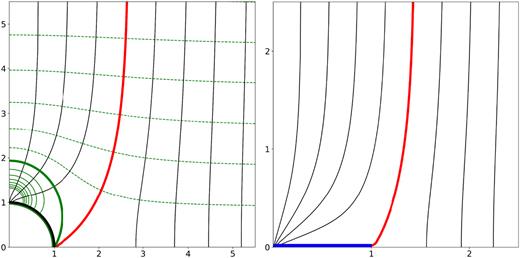
Left-hand panel: equipotential curves (χ = const.) given by equation (9) plotted in green outside of a sphere of radius a = 1. The solid green lines have χ(r, μ) > χ(1, 0), the dashed χ(r, μ) < χ(1, 0), and the thick green line corresponds to χ(r, μ) = χ(1, 0). The black lines are the field lines (Ψ =const.) found numerically. The potential lines are normal to the field lines as required. The separatrix dividing the field lines emanating from the pole to the external ones is plotted in red. Right-hand panel: the field lines (black solid lines) arising from the superposition of the split monopole and the external field. The disc where the current sheet is located in shown in blue and the separatrix in red.
2.2 Split monopole in a uniform field
Again at 0 the Q2l + 1 can be determined from the recurrence relations and the expression for Q1 given above. Unlike the sphere problem we have not obtained the solution in closed form. Thus the complete solution for |$\chi (\overline{r},\overline{\mu })$| is determined as a sum. We plot the magnetic field in Fig. 1, right-hand panel, found numerically using the method described in the model problem.
The model problem discussed above demonstrates than an infinite current sheet will be truncated and become finite once a uniform field is superposed.
3 AXISYMMETRIC PULSAR MAGNETOSPHERE IN A UNIFORM MAGNETIC FIELD
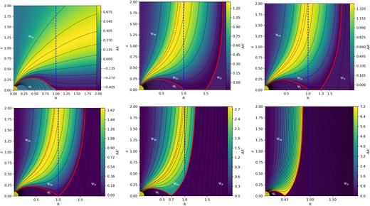
Magnetic field structure for the isolated force-free magnetosphere P0 and runs A1 and A2 (top row from left to right) and runs A3, A4, and A6 (bottom left to right). Black lines correspond to surfaces of constant Ψ, the colour scale is AA′. The thick red line is the last open field line, and the dashed blue line is the light cylinder. The dotted red line is the boundary between regions IIa and IIb. Notice the absence of regions IIb and III in the isolated pulsar solution (P0) and the absence of region IIa in the A6 solution, where no field lines starting from the pulsar cross the light cylinder.
Solutions of force-free magnetospheres confined by an external magnetic field. The columns contain the name of the model, the strength of the external magnetic field with negative being the counter-aligned configurations, the value of Ψ at the last open magnetic field line, the open magnetic flux contained within the light cylinder, and finally the location where the first field line not linked to the pulsar crosses the equator. Note that model C0 corresponds to a non-rotating dipole, where the solution is given by simple addition of the two magnetic fields.
| Name | B0 | Ψ0 | ΨLC | l0 |
|---|---|---|---|---|
| P0 | 0 | 1.30 | 0. | – |
| A1 | 0.90 | 1.71 | 0.68 | 1.50 |
| A2 | 0.98 | 1.76 | 0.74 | 1.30 |
| A3 | 1.16 | 1.86 | 0.85 | 1.00 |
| A4 | 2.25 | 2.43 | 1.59 | 0.70 |
| A5 | 5.30 | 3.17 | 2.75 | 0.50 |
| A6 | 10.0 | 3.58 | – | 0.43 |
| C0 | −5.30 | 0. | – | 0.72 |
| C1 | −5.30 | 0. | – | 0.88 |
| C2 | −10.0 | 0. | – | 0.62 |
In Gourgouliatos & Lynden-Bell (2011), we sketched the structure of the magnetosphere of a pulsar embedded in an external magnetic field. We found that the qualitative characteristics of these magnetospheres depend on the spin frequency of the pulsar, its magnetic dipole moment and the external magnetic field. Keeping the pulsar dipole strength and the external field constant we found that a slow rotator may not form an equatorial current sheet at all. Moreover, if the fields are counter-aligned the magnetosphere takes the form of a modified Dungey sphere (Dungey 1961). Rapid rotators, on the contrary, form equatorial current sheets that are truncated outside the light cylinder radius.
Let the external field be |$\boldsymbol {B}=B_{0}\boldsymbol {\hat{z}}$|. We have chosen to vary the parameter B0 instead of considering a rapid (slow) rotator as it is essentially equivalent to assume a weak (strong) external field or a strong (weak) dipole field keeping the other two parameters fixed. Essentially this expresses the ratio of the strength of the uniform field compared to the strength of the dipole field at the position of the light cylinder.
3.1 Rapid rotators – weak external field
Let us first consider a weak external magnetic field B0. This field dominates at R → ∞, whereas the pulsar dipole will dominate near the origin. An equatorial current sheet will form beyond the light cylinder up to l0, where, in analogy with the model problem, it splits into two branches flowing on the separatrix between the field lines that are connected to the pulsar and the ones that are not. The equatorial part of the current sheet carries both poloidal and toroidal currents, whereas the two branches only have poloidal currents. This is because of the discontinuities of the magnetic field. On the equator both the poloidal and toroidal components of the magnetic field are discontinuous. On the branches the poloidal field is continuous while the toroidal field is not. This is because the open field lines that are connected to the star have a toroidal component, whereas the ones beyond the separatrix are potential without any toroidal field.
We split the domain in four regions satisfying different equations. Region I contains closed magnetic field lines within the light cylinder, they are connected to the pulsar, corotate, and have no toroidal magnetic field. The flux function in this region satisfies ΨI(R, |$z$|) > Ψ(1, 0) and R < 1. Region IIa contains open magnetic field lines that are linked to the pulsar have a toroidal field, corotate, and cross the light cylinder. The flux function satisfies Ψ(1, |$z$| → ∞) < ΨIIa(R, |$z$|) < Ψ(1, 0). Region IIb contains open magnetic field lines that are connected to the pulsar, corotate, have a toroidal magnetic field but do not cross the light cylinder. The flux function satisfies ΨIIb(R, |$z$|) < Ψ(1, |$z$| → ∞). Finally, region III contains magnetic field lines not connected to the pulsar, without any toroidal field that are not corotating. The field there is potential and the magnetic flux function satisfies ΨIII(R, |$z$|) > Ψ(1, 0) and R > 1. One can see that the magnetic flux in regions I and III may have the same value but they distinguished by the fact that the former lies within the light cylinder and the latter outside.
In the isolated pulsar magnetosphere solution, the form of A = A(Ψ) is determined by the demand that the magnetic field lines cross smoothly the light cylinder. This is used for the field lines of region IIa, however, the magnetic field lines of region IIb do not cross the light cylinder, thus we cannot make use of equation (23) to determine A. In principle, one can make a choice of A(Ψ) and then find the corresponding solution. In our approach we make the choice that the poloidal magnetic field in this region is equal to the externally imposed magnetic field B0. For this to hold, the flux function needs to be Ψ(R < 1, |$z$| → ∞) = B0R2/2. Substituting this expression into equation (25) we obtain |$A A^{\prime }_{\rm IIb}=2B_{0} R^2=4\Psi$|. This choice for AA′ is then used to solve the pulsar equation in region IIb.
To integrate the pulsar equation we modify the procedure of simultaneous relaxation used in Contopoulos et al. (1999). We start from an initial trial for Ψ and A(Ψ) and use the Gauss–Sidel algorithm (Press et al. 1992) to find the corresponding solution. We use the values on either side of the light cylinder, taking the average, to correct our choice of AA′(Ψ). Then the new expression is used to integrate the equation until convergence is achieved. Similarly, we update |$AA^{\prime }_{\rm IIb}$| when we solve in region IIb. In these simulations we need to make an initial guess for the extent of the equatorial current sheet subject to the external uniform field. To do so we run several simulations with combinations of current sheet lengths and external magnetic fields until convergence is achieved. Varying the value of the external magnetic field, it changes the length of the current sheet as well in accordance to the analytical solution of the model problem: stronger magnetic fields truncate the current sheet closer to the light cylinder. We have solved for equilibria corresponding to three choices of external magnetic field leading to current sheets extending to 1.5RLC, 1.3RLC, and the limiting case where the current sheet completely disappears (Fig. 2, top row second and third panel, and bottom row first panel). We find that the last open field line has a higher value of Ψ0, thus a larger fraction of magnetic flux is in the open field line lines, see runs P1, P2, and P3 in Table 1.
Reversing the direction of the external magnetic field does not affect the pressure and tension of the magnetic field lines, therefore, the solutions still hold. Thus, this solution corresponds both to an aligned and to a counter-aligned rotator. What does change though is the current sheets forming on the separatrix between regions IIa and III: in the case of the aligned rotator the current flowing on the sheet is only poloidal due to the discontinuity of the Bϕ component, whereas in the counter-aligned case there is an extra toroidal component due to the discontinuity of the poloidal magnetic field.
3.2 Slow rotators – strong external field
In the slow rotator regime the separatrix crosses the equatorial plane within the light cylinder. Thus, no equatorial current sheet forms. Similarly to rapid rotators, we can distinguish four regions. Region I as in the rapid rotator has fields lines whose both ends are connected to the neutron star and cross the equatorial plane. Regions IIa and IIb contain field lines that emerge from the neutron star and extend to infinity, which either cross the light cylinder (IIa) or not (IIb). Finally, region III contains field lines that are not linked to the neutron star at all. The main differences between rapid and slow rotators are as follows. First, the boundaries separating regions I from IIa, and IIa from III intersect on the equator at distance l0 from the origin, where l0 < 1. Thus no equatorial current sheet forms. Secondly, very slow rotators do not have region IIb, as illustrated in solution A6 (see Table 1 and Fig. 2).
The equations corresponding to slow rotators are the same as the ones of the rapid rotator (equations 24–26) and we follow the same procedure for the determination of A = A(Ψ) demanding the field lines of region IIa to cross smoothly the light cylinder and using a linear relation AA′ = 4Ψ for the solution in IIb. With respect to the boundary conditions, we impose the same boundary conditions at R = 0, R = Rmax, |$z$| = |$z$|max, and the surface of the star is identical to those of rapid rotators. However, due to the absence of an equatorial current sheet, the boundary condition at |$z$| = 0 becomes BR(R, 0) = 0, so that the magnetic field crosses the equator perpendicularly. Subject to these constrains we integrate the differential equations and we find the structure of the magnetosphere as shown in Fig. 2, bottom row, where the equatorial current sheet has been replaced by a null point. In the solutions presented, the last open field line crosses the equator at 0.7RLC, 0.53RLC, and 0.42RLC (Table 1, runs A4, A5, and A6). Stronger uniform magnetic fields push this point closer to the star and more magnetic flux is carried by the open magnetic field lines.
Therefore, for an aligned rotator the overall magnetic field structure can be described through a continuum of states that depend on the magnetic field strength (or the spin frequency). As the external magnetic field decreases the transition between the field lines connected to the pulsar and the rest occurs at greater distances from the pulsar. A qualitative transition occurs when this happens outside the light cylinder, leading to the formation of a finite current sheet instead of a null point.
3.3 Rotating Dungey sphere
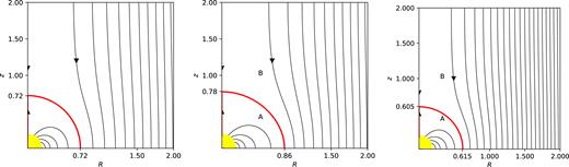
Magnetic field structure for the Dungey sphere solutions with a dipole field and a counter-aligned uniform field. The field lines connected to the star are within the red curve. Left-hand panel: model C0, a superposition of a non-rotating dipole magnetic field with an external uniform magnetic field B0 = −5.3, the field satisfies everywhere equation (27). Middle panel: model C1, magnetic field moment and external magnetic field as in the previous case, but now the dipole field is rotating at Ω = 1 so that the light cylinder is located at R = 1, the deformation from a spherical to an oblate boundary is obvious. Right-hand panel: model C2. Superposition of a magnetic field B0 = −10, to a rotating the magnetic field with unit magnetic moment, the light cylinder is located at R = 1. The deviation from a sphere in this case is minimal.
An interesting situation occurs by comparing solutions A5 and C1. Since reversing the magnetic field beyond the separatrix in solution A5 does not affect the equilibrium, we find that for the same magnetic field one can have two solutions with different topologies. One where the magnetic field emerging from the neutron star is fully confined within a sphere (C1) and another where the magnetic field linked to the pulsar extends to infinity (A5-reversed). Solution C1 does not contain a current sheet separating regions A and B, whereas A5-reversed contains a current sheet with both toroidal and poloidal currents flowing on the separatrix. This could make solution A5-reversed prone to resistive instabilities. We have evaluated the energy contained inside a cube whose side is four times the light cylinder and we have excluded a sphere at the centre whose radius is 0.2 where the star is located. We find that the open configuration contains more energy compared to the closed, in particular the difference is |$2.5 B(R_{\text{LC}},0)^2 R_{\text{LC}}^3$|, where B(RLC, 0) is the field of the dipole at the equator at a distance equal to its light cylinder. This implies that C1 is energetically favourable compared to A5-reversed. It is then likely that if a pulsar with an initially open magnetic field configuration, experiences an increasing external magnetic field, at some point to become unstable and adopt the structure of a Dungey sphere. Given the difference in energies, this change in topology will release the excess amount of energy in an explosive event.
3.4 Asymptotic behaviour
Strong external magnetic fields push the separatrix well within the light cylinder of the pulsar. While the field within the separatrix corotates, its velocity is much smaller than the speed of light. Thus, the overall dynamics are governed by the equilibrium of the dipole field with the externally imposed one. Using the flux function Ψ = R2/(R2 + |$z$|2)3/2 + B0R2/2, we can estimate the size of the corotating part of the magnetic field by finding where the separatrix intersects with the equatorial plane. At the point of intersection R0 the sign of the B|$z$| component changes from negative to positive, thus |$\frac{\text{d}\Psi }{\text{d}R}|_{z=0}=0$|, thus |$R_{0}=B_{0}^{-1/3}$| and the open flux is |$\Psi _{0}=\frac{3}{2}B_{0}^{1/3}$|, where Ψ = 1 corresponds to the flux of a non-rotating dipole at R = 1, |$z$| = 0.
For weak external fields the large distance limit is relevant. There, the system resembles a split monopole embedded in a uniform field. We can use the estimate of the model problem, equation (17), where the size of the current sheet scales as |$l_{0}\propto B_{0}^{-1/2}$|. The open flux though will be close to the value of 1.30 that is the asymptotic limit for the open field lines.
These results are consistent with the numerical results in Fig. 4. Indeed, we notice the increase of the open magnetic flux for stronger magnetic fields and the drop towards the asymptotic value for weaker fields.
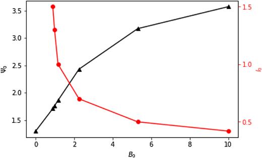
Values of Ψ0 (black triangles) and l0 (red circles) as a function of B0 for the numerical solutions found.
4 APPLICATION TO DOUBLE NEUTRON STARS
Below we explore the implications of these solutions to a DNS consisting of pulsars A and B, as its orbit shrinks due to gravitational wave radiation. Let the two members have equal masses, |$1.4\, \text{M}_{ {\odot} }$|, and radii, rNS, pulsar A period PA, dipole magnetic field BA and pulsar B period PB and dipole magnetic field BB, respectively. These magnetic fields correspond to the strengths on their surface at the equator. The distance between the two neutron stars is d. Let us further assume that A is a millisecond pulsar with a weaker magnetic field, whereas B is a young pulsar with a stronger magnetic field and slower period, thus PB ≫ PA and BB ≫ BA.
Once the two pulsars are close enough the wind of pulsar A may affect the magnetosphere of B. At smaller separations the two magnetospheres can become coupled and, depending on the relative orientation of the field, Dungey sphere configurations may appear. Finally, they come close enough to activate the unipolar inductor mechanism. These stages are schematically shown in Fig. 5.
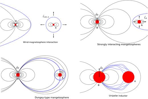
Cartoon of the stages of magnetospheric interaction in a DNS with shrinking orbit. At large separations the wind of A may deform the magnetosphere of B (top left), at closer separations, the two magnetospheres will strongly interact with the magnetosphere of A most likely developing a highly anisotropic wind (top right), or being fully confined in a Dungey sphere configuration (bottom left). Shortly before coalescence, DNSs interact through the unipolar inductor scheme (bottom right).
4.1 Wind–magnetosphere interaction
4.2 Strongly interacting magnetospheres
As the separation of the DNSs decreases, there will be a point at which the magnetic field of B at the vicinity of A will become stronger than that of A at its light cylinder. As shown in the numerical axisymmetric solutions derived in Section 3, a uniform field comparable or stronger to the pulsar’s field at its light cylinder alters the structure of the magnetosphere of the latter. While, direct application of these solutions to the thee-dimensional time-depended system that arises from such an interaction is a drastic simplification, we can still extract useful conclusions by considering the main properties of these solutions and their asymptotic behaviour.
Magnetic field lines emerging from pulsar A could either close on to pulsar A, form a wind, or connect to field lines emerging from pulsar B. Certainly, some of them will be closing on to A, forming the so-called ‘dead-zone’, however for a completely enclosed region a highly symmetric Dungey-type configuration is needed.
Let us next consider the implications of linking field lines from pulsar A to pulsar B. When the two pulsars were sufficiently far (Section 4.1), the magnetosphere of pulsar A transitioned to a wind and it was disconnected from that of B. Following their approach, and under ideal magnetohydrodynamics (MHD) conditions, the field lines maintain their topology and remain disconnected. Allowing for a finite conductivity, field lines from A could, in principle, be connected to those of B. In this case, though, as the two pulsars spin at different rates and orbit each other, these field lines will be highly twisted and wound up. A flux tube linking the two pulsars will be twisted at a rate equal to the |$P_{\rm A}^{-1}$|. Let its length be comparable to light cylinder of pulsar B (which is in the same order of magnitude of the separation of the two pulsars) |$z_\text{t} \sim cP_{\rm B}/(2{\pi})$| and its radius |$r_\text{t}\sim c P_{\rm A}/(2{\pi})$| being similar to the light cylinder of pulsar A. In a manner similar to the magnetic towers (Lynden-Bell 2003), after N spin periods of A, this process will generate a toroidal field inside the flux tube |$b_{\phi ,\text{t}}\sim {\pi} N b_{z,\text{t}} P_{\rm A}/P_{\rm B}$|, where bϕ, t and b|$z$|, t are the axial and toroidal field inside the tube. Taking their ratio to be unity |$b_{\phi ,\text{t}}/b_{z,\text{t}}\sim {\pi} N P_{\rm A}/P_{\rm B} \sim 1$| implies that the system will become unstable within after N = PB/PA rotations. At this point it will exceed the Kruskal–Shafranov limit (Kruskal et al. 1958; Shafranov 1958) and become prone to kink instability. Assuming periods of PA = 0.01 s and PB = 1 s this will happen within a second. Thus even if the field lines somehow become connected they would not maintain such a configuration long enough.
Another possibility is that pulsar A forms a wind within the magnetosphere of B. To explore the plausibility of scenario we need first to assess whether the wind pressure emanating from pulsar A is comparable or higher than the magnetic pressure of B at the neighbourhood of the former. The power of the wind will depend on the open magnetic flux emanating from pulsar A. The vacuum magnetosphere formula in equations (29) is a good approximation within a factor of a few when the strength of B is comparable to that of A at the light cylinder of the latter. Then, using the expression for the wind pressure from equation (30) we find that the pressure corresponding to a wind at a distance equal to few light cylinder of A is comparable to that of the magnetic pressure of B. Therefore, it is likely that a wind-inflated bubble could form due to the radiation of pulsar A. If such a wind appears it will be highly anisotropic and probably extend in the direction opposite from pulsar B due to the lower pressure there, Fig. 5, top right-hand panel.
Finally, we remark that as pulsar A moves with respect to the corotating plasma with a relative velocity |$\boldsymbol {v}$|, it will experience an induced |$\boldsymbol {E}=-\boldsymbol {v} \times \boldsymbol {B}/c$|. This electric field will be in the direction normal to the magnetic field, thus, even if the external magnetic field were aligned with the pulsar dipole, the presence of |$\boldsymbol {E}$| will break axial symmetry. The complete inclusion of the electric field requires a three-dimensional, time-dependent model that is beyond the scope of this work.
4.3 Unipolar inductors
5 DISCUSSION
As of now, there are 16 confirmed and candidate DNS systems, whose details are presented in Table 2. The properties of both members are only known in the eponymous double pulsar J0737 − 3039A/B Stairs 2004 whose orbital period is 2.45 h and it has a gravitational wave decay time of 86 Myr. J1946 + 2052 is an even more compact source with an orbital period of 1.88 h and a gravitational decay time of 46 Myr (Stovall et al. 2018). Among the other 14 systems, in three of them, J1755 − 2550, J1906 + 0746, and J1807 − 2500B, it is not yet confirmed whether their companions are neutron stars or white dwarfs (Lynch et al. 2012; van Leeuwen et al. 2015; Yang et al. 2017; Ng et al. 2018).
DNS and candidate sources. The columns are: pulsar name, magnetic field strength of the recycled millisecond pulsar (A) and the young pulsar (B), periods of the two pulsars, and the gravitational decay times. Decay times longer than 50 Gyr are denoted as ∞. The full set of parameters is known only for double pulsar J0737 + 3039A/B. The parameters from the first four systems of the table were used in Figs 6 and 7. The data for J1946 + 2052 are from Stovall et al. (2018). The data for all other systems were taken from Tauris et al. (2017) table 1 and references therein.
| Pulsar name | BA | BB | PA | PB | τGW |
|---|---|---|---|---|---|
| (109 G) | (109 G) | (ms) | (ms) | (Myr) | |
| J0737 − 3039 | 6.4 | 1590 | 22.7 | 2773.5 | 86 |
| J1946 + 2052 | 4.0 | – | 17 | – | 46 |
| J1913 + 1102 | 2.12 | – | 27.3 | – | 480 |
| B1913 + 16 | 22.8 | – | 59.0 | – | 301 |
| J0453 + 1559 | 3.0 | – | 45.8 | – | 2730 |
| J1518 + 4904 | 1.07 | – | 40.9 | – | ∞ |
| B1534 + 12 | 9.7 | – | 37.9 | – | ∞ |
| J1753 − 2240 | 9.7 | – | 95.1 | – | ∞ |
| J1755 − 2550a | – | 880 | – | 315.2 | ∞ |
| J1756 − 2251 | 5.5 | – | 28.5 | – | 1660 |
| J1811 − 1736 | 9.8 | – | 104.2 | – | ∞ |
| J1829 + 2456 | 1.48 | – | 41.0 | – | ∞ |
| J1906 + 0746a | – | 1730 | – | 144.1 | 309 |
| J1930 − 1852 | 58.5 | – | 185.5 | – | ∞ |
| J1807 − 2500Ba | 0.59 | – | 4.19 | – | ∞ |
| B2127 + 11C | 12.5 | – | 30.5 | – | 217 |
aSources may have companion white dwarfs.
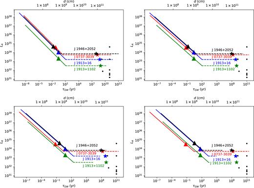
The solid line is the enhanced spin-down power of pulsar A as a function of pulsar separation in the strongly interacting magnetosphere case. The dashed line is the spin-down luminosity during wind–magnetosphere interaction, as this phase last less than the characteristic age of pulsar A, its period and period derivative do not change and the spin-down luminosity remains constant. The triangles indicate the maximum separation where the Dungey sphere configuration is feasible. The red line corresponds to the millisecond member of the double pulsar J0373 − 3039A. The black, blue, and green lines to systems where pulsar A has the properties of J1946+2052, J1913+16, and J1913 + 1102, while pulsar B is assumed to have a period of 3 s and a magnetic field of 1012, 5 × 10¹², 1013, and 5 × 10¹³ G, in the top left-, top right-, bottom left-, and bottom right-hand panels, respectively. The coloured stars correspond to spin-down power of the millisecond pulsars of the four sources used above. The black dots correspond to the other millisecond pulsars shown in Table 2.
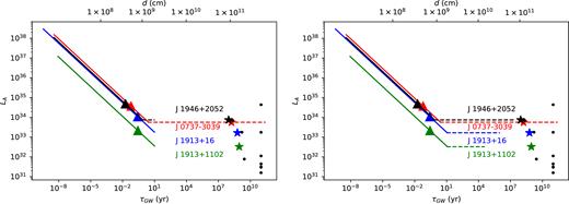
The same as Fig. 6, where pulsar B has a magnetic field of 1012 G and a period of 0.3 and 1 s, left- and right-hand panels, respectively.
5.1 The double pulsar J0733-3039A/B
Let us first consider the double pulsar J0737 − 3039A/B. This system is currently in the wind–magnetosphere interaction stage where the wind of pulsar A modifies the magnetosphere of pulsar B (Gourgouliatos et al. 2011; Perera et al. 2012; Lomiashvili & Lyutikov 2014). Indeed, while the main source of X-ray radiation is pulsar A (Chatterjee et al. 2007), there is an observable modulation due to pulsar B (Pellizzoni et al. 2008). Subsequent analysis has confirmed not only that part of the X-ray emission has a periodicity equal to that of pulsar B, but also that it is orbitally modulated (Iacolina et al. 2016). The X-ray emission from pulsar B is estimated to be >2 × 1030 erg s−1, which is 1.25 times higher than the spin-down power of pulsar B. Thus, it is impossible for pulsar B to power this radiation via its own spin-down (Egron et al. 2017). On the contrary, the spin-down power of A is 6 × 1033 erg s−1, therefore, approximately 10−3 of the spin-down power of A is modulated by pulsar B. Following the analysis of Section 4, the system will be in the wind–magnetosphere interaction phase during most of its life, until approximately 1 yr before merger when it will enter the coupled magnetosphere stage. Then, the spin-down power of pulsar A will increase by about four orders magnitude. During its final days the system may undergo a Dungey sphere state releasing rapidly large amounts of energy due to changes in the topology of the magnetosphere. Finally, the unipolar inductor will become possible only during 0.5 s prior coalescence.
5.2 Galactic DNSs
With respect to the other systems for which the magnetic field of pulsar B is unknown, we find that the results are sensitive to the strength of the magnetic field of B. A magnetic field of 1012 G leads to results similar to the double pulsar. Stronger magnetic fields for pulsar B (5 × 10¹³G) are responsible for two main differences. First, the wind–magnetosphere interaction starts later or may not occur at all. This is because the magnetic field pressure of pulsar B is too strong to be affected by the wind of A as much as in the case of a mildly magnetized neutron star. Secondly, there is an earlier onset of the coupled magnetosphere phase, starting ∼103 yr before the merger. As in the weakly magnetized case, the increase of the spin-down power of A rises by up to four orders of magnitude. During the final 20 yr before coalescence, the system will fulfil the necessary conditions for a Dungey sphere solution. Regarding the unipolar inductor phase, though the system will be capable of activating this mechanism for only a couple of seconds before merger.
A combination of a shorter period (0.3 s) and a 1012 G magnetic field for pulsar B leads to configurations where the wind–magnetosphere phase is suppressed. This is because the light cylinder of B is rather small, therefore the magnetic field of B there is much stronger compared to the wind of A, Fig. 7, left-hand panel. A longer period (1 s) for pulsar B permits a wind–magnetosphere interaction phase whose duration depends strongly on the properties of pulsar A.
Considering J1946+2052 we expect it to be in the wind–magnetosphere interaction phase if its companion is a relatively slowly rotating mildly magnetized pulsar. Should they interact, we could expect modulation of the X-ray emission of pulsar A in the period of B as in the double pulsar. Given that no X-ray source has been identified yet with J1946 + 2052, this question could be resolved using thorough deep X-ray observations.
The estimated merger rate for Galactic DNSs is |$R_{\text{g}}=21_{-14}^{+28}$| Myr−1 (Kim, Perera & McLaughlin 2015). The anticipated number of Galactic DNSs in the phases of wind–magnetosphere interaction and linked magnetospheres is a sensitive function of the magnetic fields and spin periods of the pulsars. If the double pulsar J0737 − 3039A/B is a characteristic example of the population, we anticipate that there will be ∼2 × 10⁻⁵ Galactic DNSs with a linked magnetosphere configuration. Should DNSs with 5 × 10¹³ G magnetic field for pulsar B were common the wind–magnetosphere interaction would be less frequent. In this case, the typical time spent in the linked magnetosphere phase would be 103, as permitted by such a combination of magnetic field and period. We would then anticipate 2 × 10⁻² DNSs at this stage to exist in the Galaxy. Thus, such sources would be likely to exist in the local Universe.
5.3 Implications for FRBs
While the Dungey sphere and unipolar inductor phases do not last long, they release large amounts of energy. A magnetosphere altering its topology between closed and open states, could release amounts of energy up to a fraction of the magnetospheric energy during these final stages before merger. For a millisecond pulsar the energy contained in the Dungey sphere is |${\sim } 2\times 10^{37} (B_{\rm A}/10^{10}\, {\rm G})^2$| erg, a value close to the energy range of fast radio bursts (FRBs). Given the large uncertainty in distance the actual power FRBs cannot be determined accurately. Nevertheless, taking into account the cosmological origin their energy ranges from 1038 to 1041 erg (Thornton et al. 2013; Bannister et al. 2017; Lorimer et al. 2007). Thus, the release of energy by switching from an open magnetosphere to a Dungey sphere may be marginally powerful for an FRB. More interestingly though, this switching is not a one-off event. The separation of a DNS can be such to allow this solution for a up to a few years if the magnetic field of pulsar B is 5 × 10¹³ G, or a few days for a magnetic field of 1012 G. Taking into account the DNS merger rate |$R=1540^{+3200}_{-1220}$| Gpc−3 yr−1 (Abbott et al. 2017a), we expect the number density of DNSs in the Dungey sphere phase to be within the 10–103 Gpc−3. A DNS whose separation is 109 cm has an orbital period of 10 s, thus it is likely that orientations favouring the transition between open and closed magnetospheres could occur every few periods. We remark though, that this interaction is highly non-trivial and requires a 3D study of the magnetospheres.
5.4 Pulsar spin evolution
In our discussion we have taken for granted that the spin properties of the neutron stars do not vary as their orbit shrinks. Bildsten & Cutler (1992) have shown that the inspiral is so fast that tidal interactions cannot affect the rotation of the members of the binary. Here we show that the magnetic interaction cannot have a drastic effect on the system either.
Confining the magnetosphere of pulsar A leads to an increase of its spin-down power up to four orders of magnitude compared to their vacuum spin-down power LA < 104LA, VAC. Since |$L_{\rm A}\propto P_{\rm A}^{-3}\dot{P}_{\rm A}$|, a similar increase is expected to the period derivative. As the characteristic ages of the recycled millisecond pulsars are all above 108 yr, even in the most optimistic scenario they will be scaled down to 105 yr. Since the pulsar is in the enhanced LA phase for up to103 yr, this effect is not expected to have any major implications for their spin evolution.
6 CONCLUSION
We have explored the structure of an axially symmetric rotating relativistic magnetosphere interacting with an externally imposed uniform magnetic field. We have found via analytical and numerical calculations that one of the key elements of relativistically rotating pulsar magnetospheres, the equatorial current sheet, is either truncated or even completely suppressed if the externally imposed magnetic field is sufficiently strong. An interesting feature of these structures, it that for appropriately counter-aligned magnetic fields the system may adopt different types of equilibria, either in the form of twisted magnetic fields separated by current sheets from the external magnetospheres, or a fully confined Dungey sphere solution in which no currents flow. Stronger external magnetic fields increase the fraction of open magnetic flux along which electric current flows.
The implications of this interaction for pulsar magnetospheres could be potentially important and observable when considering DNSs. Here the role of the background field is played by the young pulsar that is expected to have a stronger magnetic field and a longer period. The magnetosphere of the millisecond pulsar is modified by this field once they are close enough. Even in the optimistic scenario where the young pulsar is strongly magnetized (5 × 10¹³ G) and spins slowly (3 s) such systems would be rare: the probability of finding such a system in the Galaxy would be ∼0.02. Finally, a system interchanging states between closed and an open magnetosphere may release significant amounts of energy. Order of magnitude estimates place the available energy close to the low estimates for FRBs.
The results presented here are valid based on the assumption of axisymmetry and stationarity. Realistic systems will have a combination of orientations with orbital, spin, and magnetic moment axes misaligned, while these evolve dynamically in time. While, the conclusions of the axisymmetric system are not directly transferable to the three-dimensional case, they still provide useful insight for more realistic cases.
ACKNOWLEDGEMENTS
KNG would like to thank Ruth Lynden-Bell for hospitality in Cambridge during the summer of 2014 where the analytical and first numerical results were derived. KNG also acknowledges Andrew Cumming, Rainer Hollerbach, Ioannis Contopoulos and Nektarios Vlahakis for helpful discussions. KNG is grateful to an anonymous referee for constructive comments on the applications of the analytical and numerical solutions to double neutron star systems.
