


Abstract
We carried out an optical polarimetric study in the direction of the RCW 95 star-forming region in order to probe the sky-projected magnetic field structure by using the distribution of linear polarization segments which seem to be well aligned with the more extended cloud component. A mean polarization angle of θ = 49|$_{.}^{\circ}$|8 ± 7|$_{.}^{\circ}$|7 was derived. Through the spectral dependence analysis of polarization it was possible to obtain the total-to-selective extinction ratio (RV) by fitting the Serkowski function, resulting in a mean value of RV = 2.93 ± 0.47. The foreground polarization component was estimated and is in agreement with previous studies in this direction of the Galaxy. Further, near-infrared (NIR) images from Vista Variables in the Via Láctea (VVV) survey were collected to improve the study of the stellar population associated with the H ii region. The Automated Stellar Cluster Analysis algorithm was employed to derive structural parameters for two clusters in the region, and a set of PAdova and TRieste Stellar Evolution Code (parsec) isochrones was superimposed on the decontaminated colour–magnitude diagrams to estimate an age of about 3 Myr for both clusters. Finally, from the NIR photometry study combined with spectra obtained with the Ohio State Infrared Imager and Spectrometer mounted at the Southern Astrophysics Research Telescope we derived the spectral classification of the main ionizing sources in the clusters associated with IRAS 15408−5356 and IRAS 15412−5359, both objects classified as O4V stars.
1 INTRODUCTION
Massive star-forming regions generally are hosted by highly obscured clouds that in galaxies like the Milky Way are mainly found associated with the spiral arms (Lada & Lada 2003; Lada 2010). Also, the H ii regions generated by the massive stars formed there can be identified from the diffuse extended emission produced by the hydrogen recombination lines associated with the H α transition in the optical, with the Pa β and Br γ ones in the near-infrared (NIR), as well as by recombination line surveys like the radio one made by Caswell & Haynes (1987).
The RCW 95 Galactic star-forming region is located at l = 326|$_{.}^{\circ}$|7 and b = +0|$_{.}^{\circ}$|8 (Rodgers, Campbell & Whiteoak 1960) and presents two bright infrared nebula that can be seen in Fig. 1. Goss & Shaver (1970) performed a Galactic 5 GHz radio survey in which they found a strong continuum source with angular diameter of 3.3 arcmin, while Shaver et al. (1983), and Caswell & Haynes (1987) from radio recombination line measurements of the H109 α and H110 α transitions, found that the main radial velocity component of the associated hydrogen recombination line has a mean value of −44 km s−1, which for a standard Galactic rotation curve corresponds to a heliocentric distance of 2.4 kpc (Giveon et al. 2002). An NIR study of the stellar content of Galactic H ii regions performed by Moisés et al. (2011) gives a range of distances for the RCW95 region from kinematic and non-kinematic (trigonometric and K-band spectrophotometric parallaxes) methodologies. A kinematic distance of 2.8 ± 0.3 kpc is given and spectrophotometric distances of 1.63 ± 0.63 and 2.02 ± 0.78 kpc result by adopting two extreme interstellar extinction laws from Mathis (1990) and Stead & Hoare (2009), respectively. Dutra et al. (2003) found two stellar clusters in this Galactic H ii region located at l = 326|$_{.}^{\circ}$|66, b = +0|$_{.}^{\circ}$|59 and l = 326|$_{.}^{\circ}$|65, b = +0|$_{.}^{\circ}$|58 with angular diameters of 2 and 4 arcmin, respectively, estimated visually on the Two Micron All Sky Survey [2MASS, Skrutskie et al. (2006)] JHKs images. Also, in this region Roman-Lopes & Abraham (2004, 2006) detected two young stellar clusters, both associated with two strong compact mid- to far-infrared sources catalogued as IRAS 15411−5352 and IRAS 15408−5356. The latter presents at least 136 candidate members in an area of about 3 pc2 with about 60 per cent of them presenting some infrared excess emission at 2.2 μm, characteristic of very young stellar clusters (Lada & Lada 2003). Bik et al. (2005) and Bik, Kaper & Waters (2006) classified the K-band spectra of the brightest and most reddened sources associated with IRAS 15408−5356 and IRAS 15411−5352, determining spectral types of O5V–O6.5V and O8V, respectively.
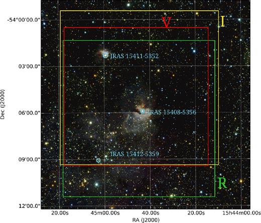
Combined RGB image from the J, H and Ks VVV images centred on RCW 95 H ii region. The coloured boxes indicate the polarization survey areas related to different spectral bands. The V optical band covers an area of 9.0 arcmin × 8.6 arcmin (red box), the R optical band covers an area of 9.6 arcmin × 10.0 arcmin (green box) and the I optical band covers an area of 10 arcmin × 10 arcmin (yellow box). Three IRAS sources in the field are indicated in light blue.
In this work, one of our goals was to study the interstellar linear polarization component in the direction of the RCW 95 Galactic H ii region. The behaviour of the magnetic field lines that permeate this star-forming region was determined, and by applying the empirical Serkowski relation (Serkowski, Mathewson & Ford 1975) to the polarimetric data, we were able to compute the total-to-selective extinction ratio (RV) mean value in this direction of the Galaxy. Also, another objective was to improve the study of the region's stellar population, which was done with point spread function (PSF) photometry on NIR VVV images, combined with J-, H- and K-band spectroscopic data taken with Ohio State Infrared Imager and Spectrometer (OSIRIS) at Southern Astrophysics Research (SOAR) telescope.
2 OBSERVATIONS AND DATA REDUCTION
2.1 Optical polarimetry
Optical VRI polarimetric data were collected with the 0.9-m telescope of the Cerro Tololo Interamerican Observatory (CTIO, Chile, operated by the National Optical Astronomy Observatory – NOAO) during two observing runs in February and April 2010.
The polarimetric module consisted of an arrangement of optical elements placed before the detector along the stellar beam path, and composed of a retarder, an analyser and a filter wheel (Magalhaes et al. 1996). The retarder is a half-wave plate positioned with an orientation relative to the North Celestial Pole (NCP), which causes a rotation of the polarization plane of the incident light beam. It can be rotated in steps of 22|$_{.}^{\circ}$|5, with each 90° rotation corresponding to a polarization modulation cycle. Finally, a Savart plate splits the beam into two orthogonally polarized components (the ordinary and extraordinary beams), with each beam passing through spectral filters before finally reaching the CCD detector.
Image reduction and photometry were done using iraf1 tasks. Point-like sources were identified and selected with the daofind task for stars with counts 5σ above the local background. Magnitude measurements were performed using aperture photometry with the phot task, for 10 different sized rings around each star.
Final calibrations of polarization zero-point angle and degree were made in order to determine possible intrinsic instrumental contribution using polarimetric standard stars observed each night and shown in Table 1. For the polarization degree the intrinsic instrumental polarization contribution is below the typical errors of ∼ 0.05 per cent. The polarization angle corrections from the standard stars correspond to the difference between the polarization angle value from the catalogue and those from our instrumental measurement (Δθ = θcat − θinst). The errors for the polarization angle were computed from σθ = 28|$_{.}^{\circ}$|65(σP/P) for P ≫ σP (Serkowski 1974).
Standard stars used for polarimetric calibrations.
| Polarized stars | ||||
|---|---|---|---|---|
| ID | Filter | P(%) | σP(%) | θ (°) |
| HD111579a | V | 6.460 | 0.014 | 103.11 |
| R | 6.210 | 0.013 | 102.47 | |
| I | 5.590 | 0.017 | 102.00 | |
| HD110984a | V | 5.702 | 0.007 | 91.65 |
| I | 5.167 | 0.007 | 90.82 | |
| HD298383a | V | 5.233 | 0.009 | 148.61 |
| HD126593a | R | 4.821 | 0.012 | 74.81 |
| Unpolarized stars | ||||
| ID | Filter | Q(%) | U(%) | |
| HD150474b | V | 0.001 | −0.007 | |
| HD126593c | V | −0.05 | −0.03 | |
The polarization survey areas are shown in Fig. 1 in different colour boxes related to each spectral band. The V optical band covers an area of 9.0 arcmin × 8.6 arcmin (red box), the R optical band covers an area of 9.6 arcmin × 10.0 arcmin (green box) and the I optical band covers an area of 10 arcmin × 10 arcmin (yellow box). A sample of the polarimetric survey is shown in Table 2.
The V, R and I optical polarimetric sample.
| α2000( h m s) | δ2000(° ΄ ″) | ID | Filter | P (%) | σP (%) | θ (°) | σθ (°) |
|---|---|---|---|---|---|---|---|
| 15:44:30.09 | −54:03:04.9 | 193 | V | 5.698 | 1.080 | 51.22 | 5.42 |
| R | 7.388 | 0.513 | 59.24 | 1.98 | |||
| I | 5.401 | 0.697 | 56.01 | 3.69 | |||
| 15:44:34.22 | −54:03:06.4 | 194 | V | 6.181 | 0.270 | 55.82 | 1.25 |
| R | 6.170 | 0.185 | 56.64 | 0.85 | |||
| I | 5.017 | 0.275 | 56.01 | 1.57 | |||
| 15:44:32.92 | −54:03:09.1 | 195 | V | 6.386 | 1.023 | 56.62 | 4.59 |
| R | 5.717 | 0.412 | 61.14 | 2.06 | |||
| I | 6.379 | 0.780 | 56.81 | 3.50 | |||
| 15:45:11.06 | −54:03:08.9 | 196 | V | 3.147 | 3.226 | 61.22 | 29.36 |
| R | 3.082 | 0.443 | 53.44 | 4.12 | |||
| I | 1.739 | 0.420 | 60.11 | 6.91 | |||
| 15:45:18.10 | −54:03:10.7 | 197 | V | – | – | – | – |
| R | – | – | – | – | |||
| I | 8.575 | 4.233 | 45.41 | 14.14 | |||
| 15:44:41.78 | −54:03:11.6 | 198 | V | – | – | – | – |
| R | 4.156 | 0.708 | 60.24 | 4.88 | |||
| I | 6.004 | 0.867 | 57.61 | 4.13 |
Note. Polarization angle and degree values marked with − correspond to objects without data in this specific spectral band.
2.2 Near-infrared photometry
The NIR photometric image data in the J (1.25 μm), H (1.65 μm) and Ks (2.15 μm) bands were retrieved from the ESO Public Survey VVV designed to scan the inner Milky Way (Minniti et al. 2010) with the VISTA InfraRed CAMera (VIRCAM) at the 4.1-m Telescope at Cerro Paranal Observatory, in Chile (Sutherland et al. 2010). VIRCAM provides observations with a field of view of 1|$_{.}^{\circ}$|48 × 1|$_{.}^{\circ}$|11 and a spatial resolution of 0.34 arcsec per pixel. In this study we have selected the Tile d098 in the J, H and Ks bands of the VVV survey covering the field of RCW 95 H ii region around |$\alpha _{{\rm J}2000}=15^{\rm h}44^{\rm m}5{^{\rm s}_{.}}5$| and δJ2000 = −53°54΄24″, which comprises the area of the polarimetric survey in this work.
Because of crowding within the RCW 95 H ii region, PSF photometry was performed using iraf tasks from the daophot package (Stetson 1987) for stars peaked 10σ above the local background. The best fitting for the PSF was obtained from ‘penny2’ function. The PSF radius and PSF fitting radii used for each filter are indicated in Table 3. The PSF fitting and stellar subtraction process were run several times in order to reveal and obtain the magnitudes for the very close faint companions in the most crowded areas. The completeness limits values for J, H and Ks bands are 18.5, 18.2 and 16.7 mag, respectively, and were estimated from the distribution of cumulative star counts as a function of magnitude, as shown in Fig. 2, where a linear relation was fit to determine the point at which the number of detected sources decreases in the distribution. The above completeness limits represent an improvement of about 1.1, 2.0 and 3.1 mag in the J, H and Ks bands, respectively, when compared to the earlier survey (aperture photometry) by Roman-Lopes & Abraham (2004). The completeness resulting from this procedure are similar to artificial star tests for uncrowded fields as shown by Maia, Moraux & Joncour (2016). In order to recover photometric information from saturated stars in the VVV images they were replaced with 2MASS magnitudes transformed to the VVV photometric system according to Soto et al. (2013). A sample of the photometric results is shown in Table 4.

Cumulative source counts as function of magnitude used to derive the completeness limit (cl) for each filter indicated by the vertical dashed lines.
List of PSF radii and PSF fitting radii for each filter applied for the PSF photometry.
| J | H | Ks | ||||
|---|---|---|---|---|---|---|
| (pixels) | (arcsec) | (pixels) | (arcsec) | (pixels) | (arcsec) | |
| PSF radius | 11 | 3.74 | 11 | 3.74 | 11 | 3.74 |
| PSF fitting radius | 2.5 | 0.85 | 3.9 | 1.326 | 3.7 | 1.258 |
| J | H | Ks | ||||
|---|---|---|---|---|---|---|
| (pixels) | (arcsec) | (pixels) | (arcsec) | (pixels) | (arcsec) | |
| PSF radius | 11 | 3.74 | 11 | 3.74 | 11 | 3.74 |
| PSF fitting radius | 2.5 | 0.85 | 3.9 | 1.326 | 3.7 | 1.258 |
NIR photometric sample from VVV data. Columns 1 and 2 are the equatorial coordinates (α, δ)J2000. The following columns are the magnitudes together with each corresponding uncertainties.
| α2000( h m s) | δ2000(° ΄ ″) | J | ΔJ | H | ΔH | Ks | ΔKs |
|---|---|---|---|---|---|---|---|
| 15:45:04.13 | −54:03:35.4 | 14.396 | 0.020 | 10.256 | 0.024 | 8.037 | 0.018 |
| 15:45:09.82 | −54:10:37.9 | 14.353 | 0.023 | 10.277 | 0.024 | 8.106 | 0.021 |
| 15:43:55.29 | −53:48:49.2 | 13.531 | 0.026 | 11.077 | 0.022 | 9.932 | 0.019 |
| 15:43:12.50 | −54:23:27.9 | 13.965 | 0.030 | 11.345 | 0.030 | 10.043 | 0.021 |
| 15:42:27.68 | −53:54:36.7 | 17.890 | 0.027 | 13.514 | 0.023 | 11.480 | 0.025 |
| 15:45:20.00 | −54:00:16.2 | 17.734 | 0.031 | 13.943 | 0.020 | 12.066 | 0.026 |
| 15:42:22.11 | −54:20:20.7 | 14.938 | 0.021 | 13.087 | 0.021 | 12.197 | 0.024 |
| 15:43:26.96 | −54:27:48.9 | 14.904 | 0.022 | 13.129 | 0.058 | 12.204 | 0.023 |
| 15:39:59.02 | −54:05:54.6 | 15.815 | 0.032 | 13.924 | 0.025 | 13.045 | 0.025 |
| 15:43:35.90 | −54:17:29.4 | 18.222 | 0.031 | 15.370 | 0.030 | 14.019 | 0.020 |
2.3 Near-infrared spectroscopy
NIR spectroscopic observations for the two brightest sources selected from our photometric study were performed with the OSIRIS at the SOAR telescope. The J-, H- and K-band spectroscopic data were acquired on 2015 April 4, with the night presenting good seeing conditions. We also used the NIR spectra of HD 303308 as template and the spectroscopic data for this object was acquired by Alexandre Roman-Lopes on 2007 March 4. Table 5 summarizes the NIR observations.
Summary of the SOAR-OSIRIS data set used in this work.
| Date | 2007 April 3 |
| 2015 April 4 | |
| Telescope | SOAR |
| Instrument | OSIRIS |
| Mode | XD |
| Camera | f/3 |
| Slit | 1 arcsec × 27 arcsec |
| Resolution | 1000 |
| Coverage (μm) | 1.25–2.35 |
| Seeing (arcsec) | 0.8–1.1 |
| Targets | IRS1/IRS2/HD303308 |
| Date | 2007 April 3 |
| 2015 April 4 | |
| Telescope | SOAR |
| Instrument | OSIRIS |
| Mode | XD |
| Camera | f/3 |
| Slit | 1 arcsec × 27 arcsec |
| Resolution | 1000 |
| Coverage (μm) | 1.25–2.35 |
| Seeing (arcsec) | 0.8–1.1 |
| Targets | IRS1/IRS2/HD303308 |
The spectroscopic data set was reduced following standard NIR reduction procedures that are detailed in Roman-Lopes (2009), and shortly explained here. The dispersed images were subtracted for each pair of images taken at the two positions along the slit. Next the resultant images were divided by a master normalized flat, and for each processed frame, the J-, H- and K-band spectra were extracted using the iraf task APALL, with subsequent wavelength calibration being performed using the IRAF tasks IDENTIFY/DISPCOR applied to a set of OH sky line spectra (each with about 30–35 sky lines in the range 12 400–23 000 Å). The typical error (1σ) for this calibration process is estimated as ∼12 Å which corresponds to half of the mean FWHM of the OH lines in the mentioned spectral range. Telluric atmospheric corrections were done using J-, H- and K-band spectra of A-type stars obtained before and after the target observations. The photospheric absorption lines present in the high signal-to-noise telluric spectra were subtracted from a careful fitting (through the use of Voigt and Lorentz profiles) to the hydrogen absorption lines and respective adjacent continuum. Finally, the individual J-, H- and K-band spectra were combined by averaging (using the iraf task SCOMBINE) with the mean signal-to-noise ratio of the resulting spectra being well over 100.
3 RESULTS AND ANALYSIS
3.1 Optical polarimetry
3.1.1 Map of the distribution of polarization segments
From the optical polarimetric survey it was possible to derive the spatial distribution of the linear polarization segments in the direction of RCW 95. The resulting R-band map can be seen in Fig. 3. There they are represented by green segments of line that are plotted on a RGB composite image (centred on the main cluster) made from the J (blue), H (green) and Ks (red) bands of VVV images, with each segment representing the degree of polarization and polarization angle (P and θ, respectively) of each star with good photometric measurements in the observed field. The size of each segment is proportional to the polarization degree (the scale reference for a 5 per cent polarization degree is indicated at the top-right corner of the map), and the orientation representing the polarization angle measured from NCP (equatorial reference). As a complement and in order to identify a possible correlation between the magnetic field component projected on to the plane of the sky, and the more extended dust component of the molecular cloud, we also constructed a contour map that was derived from a Spitzer-MIPS 70 μm image taken from the NASA/IPAC Infrared Science Archive (IRSA2).
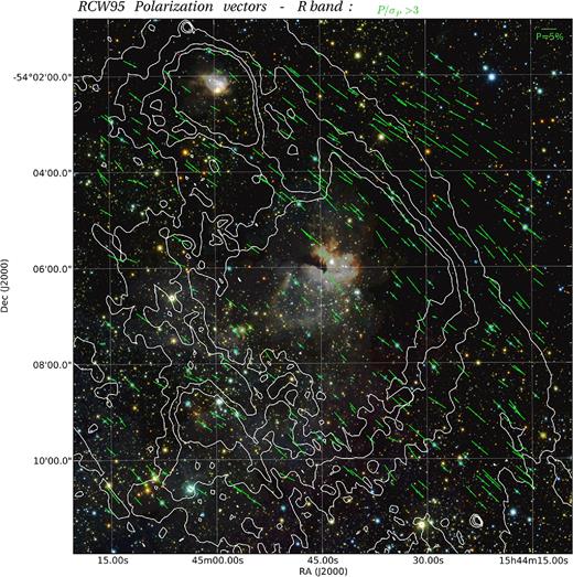
Spatial distribution map of the R-band polarization segments in the direction of the RCW 95 H ii region (area ∼ 10 arcmin × 10 arcmin) with north to the top and east to the left. The sizes of each segment are proportional to the polarization degree (an equivalent to a 5 per cent polarization degree segment is indicated in the right corner of the image). Each segment's orientation is measured from the NCP. Just P/σP > 3 data are shown. The contour lines correspond to the Spitzer-MIPS 70 μm over an RGB composition from VVV data in the J, H and Ks bands.
The polarization angle maps appear similar in all spectral bands, with the mean values being compatible considering the uncertainties (〈θV〉 = 51|$_{.}^{\circ}$|2 ± 7|$_{.}^{\circ}$|6, 〈θR〉 = 49|$_{.}^{\circ}$|8 ± 7|$_{.}^{\circ}$|7 and 〈θI〉 = 49|$_{.}^{\circ}$|4 ± 8|$_{.}^{\circ}$|9). As can be seen from the polarization map distribution obtained for the R-band data, Fig. 3, our sample contains a high number of sources with polarization values obeying the condition P/σP > 3 (82 per cent, 88 per cent and 78 per cent for the V, R and I bands, respectively). In the analysis of the results, we choose to be conservative by excluding all sources presenting P/σP values not satisfying the mentioned condition. Indeed, from an inspection of the results obtained for the associated objects, it was concluded that most of them correspond to bad quality data measurements mainly resulting from the presence of bad pixels, cosmic rays on the detector and/or sources close to the borders of the images, where the photometric sensitivity drops considerably. However, in order to enrich the discussion sometimes the low-quality polarimetric data corresponding to sources with P/σP < 3 were also used in order to complement the associated analysis.
As can be seen from the background NIR composite image (Fig. 3), the interstellar extinction in this direction of the Galaxy is high and highly variable, with the two star clusters clearly seen to the centre and to the north-east, apparently associated with the most optically obscured parts of the region. Also, the spatial distribution of the two clusters seems well correlated with the 70 μm contours with the extended cloud surrounding them in a somewhat elongated geometrical configuration. This is important because it could indicate that in this case the expansion of the H ii regions tends to follow the magnetic field (B) lines perhaps suggesting a correlation between the mean B orientation and the Galactic plane. In this sense, we can see that the overall polarization segment distribution seems to be well aligned with the more extended cloud component, with a mean polarization angle of 49|$_{.}^{\circ}$|8 as inferred from the histograms of polarization angles in Fig. 4. In this figure we highlight the three distributions related to the P/σP quality data criteria stated above. There the blue one corresponds to sources with P/σP > 3 (‘good quality data’). A Gaussian fit was applied to each distribution resulting in a mean polarization angle for the R band of θR = 49|$_{.}^{\circ}$|8 ± 7|$_{.}^{\circ}$|7. There is a correlation in the mean value for all quality data but with higher dispersion towards lower values of P/σP up to σθ = 10|$_{.}^{\circ}$|2 for the red distribution. In addition, in order to evaluate some correlation between the mean B orientation and the Galactic plane it is possible to convert the polarization angles from equatorial to Galactic coordinates according to Stephens et al. (2011). The Galactic polarization angle for the R band is then θG = 87|$_{.}^{\circ}$|0 which means that the mean B orientation shows a good correlation with the Galactic plane (the position angle of Galactic plane is 90°).
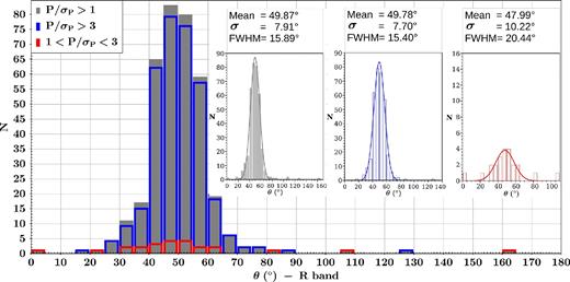
R-band polarization angle histograms. Each colour represents the quality data where grey corresponds to all data with P/σP > 1, blue for data with P/σP > 3 and red for data with 1 < P/σP < 3. The mean polarization angle from a Gaussian fit to each distribution results in 49|$_{.}^{\circ}$|87, 49|$_{.}^{\circ}$|78 and 47|$_{.}^{\circ}$|99 for the grey, blue and red distributions, respectively. There is an increase in the dispersion with lower values of P/σP (from σθ = 7|$_{.}^{\circ}$|70 for the blue distribution up to σθ = 10|$_{.}^{\circ}$|22 for the red one).
The histograms for the observed values of the polarization degree are shown in Fig. 5. There we also can see those corresponding to the three distributions described earlier as shown in Fig. 4. The polarization degree values for the best quality data ranges between P = 0-10 per cent with the higher frequencies occurring for values between P = 3-6 per cent (with ∼ 60 per cent of the blue distribution sources lying within this range). The red distribution does not show any apparent preferential range of polarization degree values; however, they correspond to the 11 per cent of the R band entire sample.
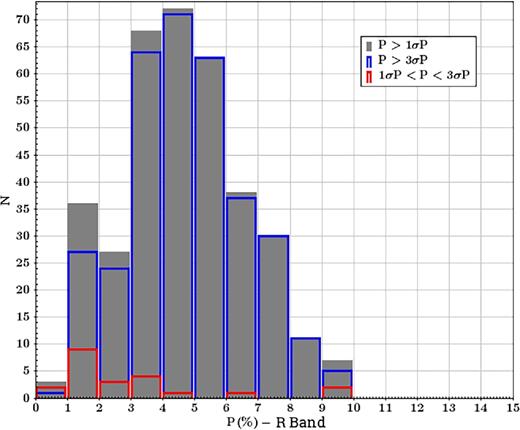
R-band polarization degree histograms. Coloured distributions correspond to the quality data criteria used in Fig. 4. The polarization degree for P/σP > 3 data ranges between P = 0-10 per cent with a higher frequencies between P = 3-6 per cent ( ∼ 60 per cent of the blue distribution sources lies within this range).
3.1.2 Wavelength dependence of polarization degree and the observed total-to-selective extinction ratio
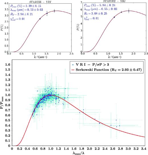
(Top) Serkowski fitting in a P( per cent) versus λ− 1 (μm− 1) diagram for two sources whose polarimetric parameters obey the criteria P/σP > 3 and belong to the set of curves with best fits (lower values of the reduced chi-square |$\chi ^2_{{\rm red}}$|). Each fitted value of Pmax, λmax and RV is listed at the top. (Bottom) Serkowski relation in a P/Pmax × λmax/λ diagram for all sources obeying P/σP > 3 as well as |$\chi ^2_{{\rm red}}<2$| (blue dots with their error bars in light-blue). The red line indicates the Serkowski fit for RV = 2.93 ± 0.47.
In order to calculate the mean value of RV in the direction of RCW 95, we applied the fitting process only to the sources presenting |$\chi ^2_{{\rm red}} < 2$| from the Serkowski relation fitting. From the entire sample, 106 sources meet the mentioned conditions resulting in a mean total-to-selective extinction ratio value (weighted average) RV = 2.93 ± 0.47 which, given its uncertainty, can be compared to the standard value of RV = 3.09 ± 0.03 for Galactic interstellar grains (Rieke & Lebofsky 1985).
In the bottom panel of Fig. 6 we present the Serkowski relation plotted over the 106 sources (blue dots with error bars in light-blue) used to compute the mean RV value in the direction of RCW 95. The uncertainties on the derived polarimetric parameters increase to the right side of the plot just towards lower λ values, as expected because the heavy extinction in general contributes to decrease the signal-to-noise ratio values towards bluer colours, mainly for the stars in the direction of RCW 95.
3.1.3 Foreground R-band polarization component
For an assumed heliocentric distance of 2.4 kpc (Giveon et al. 2002), it is expected that at least part of the polarization levels measured for the stars in our sample are possibly affected by a line-of-sight foreground interstellar component. In this sense, we proceed to estimate this foreground contribution by using the NIR photometric colours of the probable foreground and background sources, taking into account the observed connection with the associated polarimetric parameters. The NIR photometric colours taken from the results presented in Section 3.2 were correlated with our polarimetric sample to identify the sources corresponding to the main-sequence and red-giant and/or supergiant Galactic disc population, as can be seen in Fig. 7. There the blue distribution corresponds to the low-reddened sources in the colour–magnitude diagrams (CMD), which in turn are associated with the main-sequence disc stars. On the other hand, the probable giant field sources (e.g. those mainly located behind the star-forming region) correspond to the red dots. Both the blue and the red sample were manually selected from the mentioned locus in the CMD avoiding to select sources located in ambiguous position in the diagram. The observed polarization degree distributions of these two groups of objects are shown in Fig. 8, which is colour coded in the same way. We can see that the polarization degree levels for the foreground sources peak around PR = 2.0 per cent, with no background sources showing polarization degree lower than this value in the red distribution, which we assume as the probable mean value of the foreground component of the interstellar polarization value in this direction of the Galaxy.
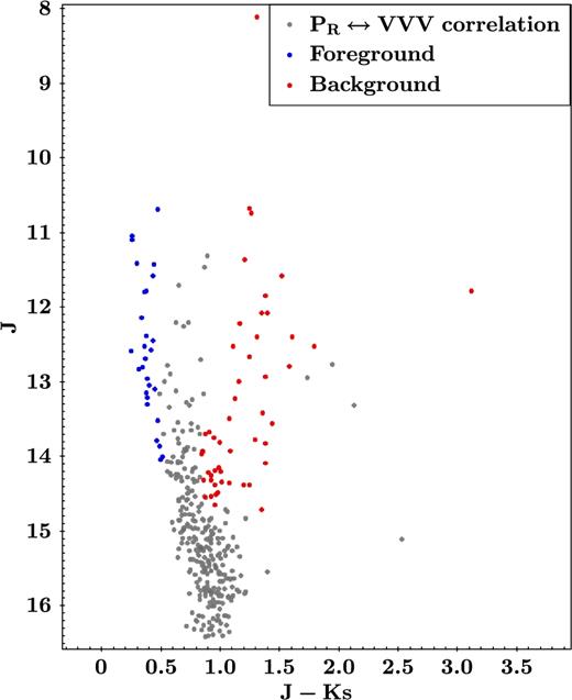
Colour–magnitude diagrams from the correlation between R polarimetric and JHKs photometric catalogues. There are shown in red dots sources with high extinction along the reddening band that most probably are giant field Galactic sources behind the star-forming region (background stars). Blue dots correspond to foreground sources with lower interstellar absorption values around the unreddened main-sequence locus.
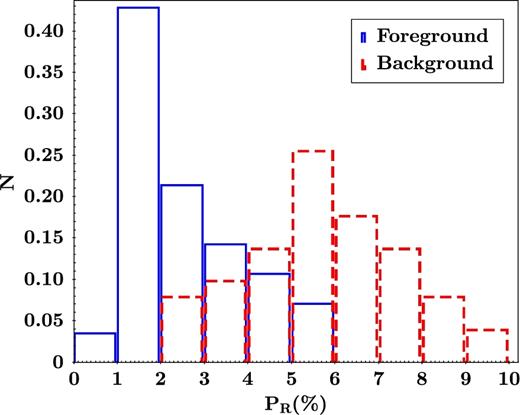
R-band polarization degree (PR) histograms. Sources identified as foreground population are indicated by blue dots while red ones are those identified as background population, according to the analysis from Fig. 7.
We also analysed the polarization angle distribution for stars with PR < 2.0 per cent and PR > 2.0 per cent, and by Gaussian fittings we estimated the mean polarization angle associated with each distribution. The results are shown in Fig. 9. The angles θ = 43° for the foreground component and θ = 50° for the background component show that there is no significant difference between the polarization angle for the two source groups resulting in a mean polarization angle of θ = 46|$_{.}^{\circ}$|5 ± 8|$_{.}^{\circ}$|5. From a search in the associated literature we found that Mathewson & Ford (1970) derived values P = 2.19 per cent and θ = 51° for HD 141318, a star in the vicinity of the RCW 95, both values well in line with our estimates for the mean polarization angle and foreground polarization component in this part of the Galaxy.
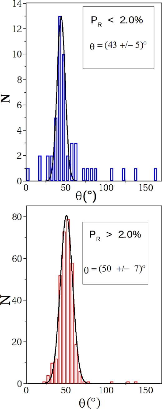
Polarization angle distribution for sources presenting PR < 2.0 per cent (top panel) and those presenting PR > 2.0 per cent (bottom panel) from the R-band polarimetric catalogue.
3.2 VVV near-infrared photometric study
In the following sections we describe the study of the stellar population in the direction of the RCW 95 H ii region. The stellar clusters studied are those associated with the infrared sources IRAS 15408−5356 and IRAS 15412−5359, hereafter identified as 15408 and 15412, respectively.
3.2.1 Cluster parameter determinations
The initial reference coordinates for each cluster are those of the IRAS sources, which are |$\alpha _{\rm J2000}=15^{\rm h}44^{\rm m}42{^{\rm s}_{.}}8$| and δJ2000 = −54°05΄56″ for IRAS 15408−5356 and |$\alpha _{{\rm J}2000}=15^{\rm h}45^{\rm m}03{^{\rm s}_{.}}4$| and δJ2000 = −54°09΄08″ for IRAS 15412−5359. In order to determine the best values of the centre for each cluster, we made use of the Automated Stellar Cluster Analysis (ASteCA) algorithm (Perren, Vázquez & Piatti 2015). The latter allowed us to compute the central coordinates of the cluster as the point with maximum spatial density value, by fitting a two-dimensional Gaussian kernel density estimator (KDE) to the density map of each cluster. In Fig. 10 we show the results of the 2D Gaussian KDE fitting for 15408 (middle) and 15412 (bottom). The area values used for each centre computation are indicated in the upper panel of the figure, with the red and green boxes corresponding to the clusters 15408 and 15412, respectively. As a complement, we also indicate by a yellow box, the area corresponding to the field shown in Fig. 1.
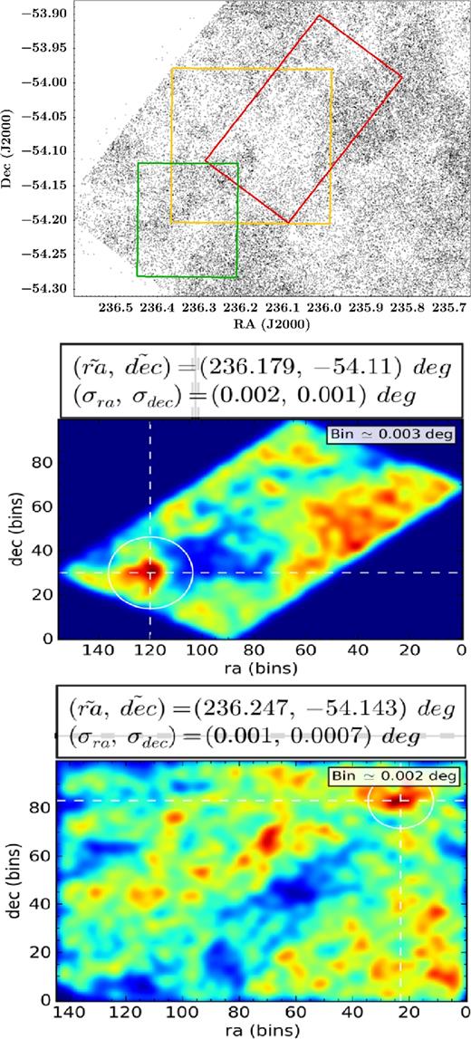
(Top) Areas of the centre determination analysis were red and green corresponding to the areas of the clusters 15408 and 15412, respectively. The middle and bottom panels show the centre determination via a two-dimensional KDE. In the header of each panel are shown the centre coordinate values together with its uncertainties.
The RDP determination for both clusters was then performed using the ASteCA algorithm, which computes the RDP by generating square rings of increasing sides via an underlying 2D histogram (grid) in the spatial diagram of the analysed region, counting the stars within each square ring and dividing by its area. In Fig. 11 we show the RDP obtained for the clusters 15408 and 15412, where each dot represents the number of stars per unit area as described above, with the associated uncertainties represented by the error bars. The horizontal blue line indicates the σf value, the red arrow indicates the determined rcl value and the grey region indicates the associated uncertainty. The three-parameter King profile (King 1962) is indicated by the dashed green line and the core radius is represented by the vertical green line. The tidal radius of the cluster's King profile is indicated by the green arrow. In Table 6 we list all parameter values obtained from the RDP analysis, where the different radii are shown in two rows, the upper one shows them in degrees and the lower one in parsecs. This result suggests that the two clusters found by Dutra et al. (2003), for which the estimation of centres and angular dimensions were based on visual inspection on the 2MASS Ks images, actually correspond to the single cluster 15408 in this work.
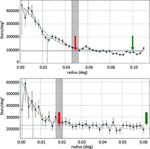
Radial density profile of the regions of clusters 15408 and 15412. The black dots correspond to the RDP point from the centre of each cluster. The three-parameter King profile is represented by the dashed green line, the vertical green line indicates the cluster core radius and the tidal radius is represented by the green arrow. The horizontal blue line indicates the σf value and the cluster radius with its uncertainties are indicated by the red arrow and the grey region, respectively.
Structural parameters of both clusters 15408 and 15412.
| ID cluster | Centre | Cluster radius (rcl) | Core radius (rc) | Tidal radius (rt) |
|---|---|---|---|---|
| (RA ± σRA, Dec. ± σDec.)J2000 | (°) | (°) | (°) | |
| (pc) | (pc) | (pc) | ||
| 15408 | (236.179 ± 0.002, −54.11 ± 0.001) | 0.049 ± 0.003 | 0.024 ± 0.003 | 0.1 ± 0.03 |
| 2.05 ± 0.13 | 1.01 ± 0.13 | 4.19 ± 0.13 | ||
| 15412 | (236.247 ± 0.001, −54.143 ± 0.001) | 0.019 ± 0.002 | 0.006 ± 0.002 | 0.06 ± 0.06 |
| 0.80 ± 0.08 | 0.25 ± 0.08 | 2.51 ± 2.51 |
3.2.2 Luminosity and mass functions
The LF of the RCW 95 region was evaluated by adding together the identified members from both 15408 and 15412 clusters. A MK LF was built by applying the distance modulus and reddening corrections to the stars magnitude and binning the sample using a 0.75 mag interval. A Monte Carlo procedure was used to propagate both the photometric uncertainties and the adopted extinction uncertainty into an LF uncertainty, by assuming a normal error distribution. The resulting LF is shown in Fig. 12.
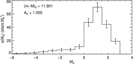
MK luminosity function of the RCW95 region. Error bars were calculated using a Monte Carlo procedure to propagate photometric and extinction uncertainties. The adopted distance modulus and extinction corrections are also shown.
Fig. 13 shows the resulting MF for the RCW 95 region, along with the derived total mass of observed stars. Since we are taking advantage of measurements in three bands, the total mass was obtained through an average of the summation in each band. The mass spectrum shows a power-law behaviour at masses higher than 2 M⊙, but flattens for lower masses in all filters. This result was also found in the MF of each cluster individually, albeit at a lower confidence level, specially for cluster 15408.

MF of the RCW95 region, as derived from the J (triangles), H (squares) and Ks (diamonds) bands. The total stellar mass observed and the power-law slope fitted to the higher mass bins (solid line) are also shown. Dotted lines show the region where stars do comply with the IMF within 1σ.
A fit of the stellar initial mass function (IMF), modelled by a power law of the form ξ(m) = Am−α (Kroupa et al. 2013, hereafter K13), was performed on the higher mass bins (m ≥ 2 M⊙) yielding a slope of α = 2.29 ± 0.12, in accordance with the expected IMF slope at this mass range. The flattening at lower mass bins probably signals higher than average incompleteness towards the clusters rather than selective mass-loss driven by evolutionary effects. Although the cutoff limit at 2 M⊙, corresponding to K ∼ 15.5, is about 1 mag brighter than the derived completeness limit, crowding and higher extinction in young clusters is known to cause an increase in incompleteness towards its centre with relation to the mean incompleteness value derived from stellar counts (Maia et al. 2016).
Given the youth of the region, it is unlikely that stars as massive as a solar mass star have been depleted by dynamical effects such as stellar evaporation. Therefore, the MF normalization (calculated at 2 M⊙) was used to extrapolate K13 IMF down to the hydrogen burning limit (0.08 M⊙). Integration of this function to recover the unseen stellar content yielded a total stellar mass of 1220 ± 213 M⊙ for the RCW95 region, with 39 per cent held by the cluster 15408 and 61 per cent held by the cluster 15412.
3.2.3 Near-infrared spectroscopic classification of the most massive members and cluster ages
Through the use of CMDs built from the JHKs VVV photometry, combined with NIR follow-up spectroscopic observations of the main sources in each cluster, we were able to obtain valuable information about the stellar population of each cluster. The CMD in the direction of each cluster contain sources of both, background and foreground Galactic disc population. As a consequence the observed CMDs are the result of a mix of young and old stellar sources that in principle are difficult to interpret. In order to relieve this effect, we applied the decontamination method described in Maia, Corradi & Santos (2010), which is based on a statistical comparison between the observed CMD for each cluster and those in the direction of associated control regions. It enables the decontamination of the Galactic field population from the CMD of the cluster. The areas for the decontamination procedure were chosen accordingly with the results obtained in Section 3.2.1, which are summarized in Table 6. The same control region was used for the decontamination of both clusters, which is centred at |$\alpha _{\rm J2000}=15^{\rm h}44^{\rm m}38{^{\rm s}_{.}}6$| and δJ2000 = −54°18΄53″ (measuring about 2.8 × 2.8 arcmin2). It was selected from the visual inspection of the Spitzer 3.6 and 8.0 μm images of the region, looking for adjacent regions showing no extended emission at longer wavelengths, with the aim of avoiding as much as possible the areas immersed in the associated molecular complex. Finally, among all the possible control regions, we selected the nearest field with similar Galactic latitude b.
The resulting CMDs for each cluster are shown in Fig. 14 where the left-hand panels correspond to the observed CMD in the direction of each cluster, the middle panel shows the CMD made from the sources found in the direction of the control region, while the decontaminated CMD for each cluster are represented by the right-hand panels. We also indicate there the two sources for which we obtained NIR spectroscopic data that enabled us to refine the classification of the main ionizing source of the 15408 cluster, as well as to confirm the massive nature of the brightest source in the CMD of the 15412 cluster. From an inspection of the two decontaminated CMDs, we can see that the associated vertical main-sequences are both seen at (J−Ks) ∼ 2.0 with the probable turn-on regions occurring approximately at J ∼ 16 mag, indicating that the two clusters are under about the same amount of interstellar extinction, and probably have similar ages.
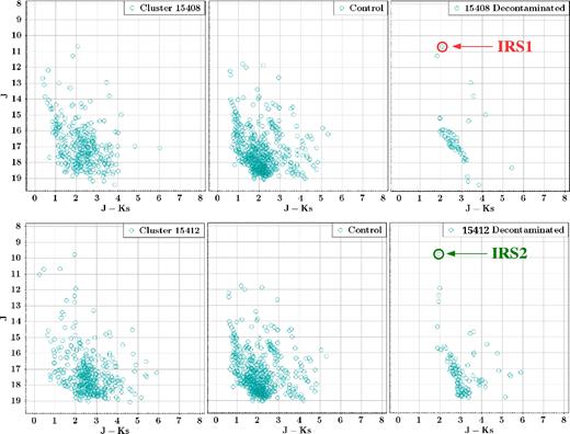
Colour–magnitude diagrams J × (J − Ks) of the clusters 15408 and 15412. (Left) CMD in the direction of each cluster. (Middle) CMD in the direction of the control region. (Right) Decontaminated CMD of each cluster. There were labelled those sources with NIR spectra (IRS1 and IRS2).
Fig. 15 shows the combined CMD containing point sources from the 15408 and 15412 clusters, which are represented by the red and green symbols, respectively. In this diagram we represent by the blue dashed line the non-reddened 3.2 Myr parsec (Bressan et al. 2012; Chen et al. 2015) isochrone (solar metallicity shifted to a heliocentric distance of 2.4 kpc), with each mass in the interval 5–80 M⊙ indicated. There we also show a set of parsec isochrones computed for ages 2.0, 3.2 and 5 Myr, reddened by AV = 11 and 13.
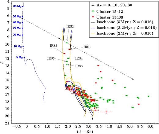
CMDs J × (J − Ks) of the decontaminated clusters 15408 (red) and 15412 (green). The yellow, blue and black solid lines correspond to a 2, 3.2 and 5 Myr isochrones at AV = 11–13 with Z = 0.016 for a distance of 2.4 kpc. The dashed blue line corresponds to the unreddened 3.2 Myr isochrone where the respective stellar masses for MS stars are indicated. The dashed black line indicates the reddening vector for a O4V star (Martins et al. 2005) indicating the location of AV = 0, 10, 20 and 30 mag according to interstellar extinction law from Rieke & Lebofsky (1985) using the RV = 2.93 ± 0.47 from the polarimetric study. Stars marked with IRS1-6 labels are those in Table 7.
From the position of sources IRS1 and IRS2 in the CMD of Fig. 15, and accordingly with the stellar models, we can see that both stars are probably very luminous objects with inferred masses of 40–50 M⊙, which according to Martins et al. (2005) should correspond to stars of O4V–O5V types. With our new SOAR-OSIRIS NIR spectra taken for the two brightest source in both clusters we confirmed this assumption. The associated J-, H- and K-band spectra of IRS1 and IRS2 stars are presented in Fig. 16. We also show the J-, H- and K-band template spectra of HD 303308, a known O4V Galactic star. From the comparison of the former with the template spectra we can see that besides the residual hydrogen emission line features present in the IRS1 spectra, which could not be completely removed during the reduction process, all other photospheric lines seen in the J, H and K bands are pretty similar, indicating that the three stars are probably of the same spectral type. Indeed, the J-, H-, K-band spectral features of IRS1 and IRS2 are very similar (besides the residual hydrogen emission line present in the spectra of the former) to those of HD 303308 (O4V) and HD 46223 (O4V) (Hanson et al. 2005). The fact that the He i λ17007 absorption lines are less intense than the He ii λ16930 lines, and the presence of He ii λλ21890 absorption lines in the K band, along with strong C iv and N iii λλ20800–21160 emission lines of similar intensity in all K-band spectra, led us to the conclusion that both sources are indeed early O-type stars probably of the O4V type. This spectral classification of the source IRS1 represents a more accurate classification than that previously determined by Roman-Lopes et al. (2009) where they suggest a O5.5V type based in spectroscopic data in the K band only, obtained with the Gemini Near-Infrared Spectrograph in Gemini South. Our new classification incorporates the analysis of J and H bands which include important spectral lines of hydrogen and helium for a further discrimination between early O-type stars.
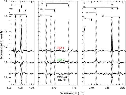
NIR spectra for the IRS 1 and IRS 2 sources in the J, H and K bands. The reference spectra of the HD303308 star of known spectral type O4V.
Bik et al. (2005) performed a K-band spectral classification of IRAS point sources that were selected based on their position in the colour–magnitude diagram (CMD), where the source 15408nr1410, presenting (J − Ks) = 2.2 ± 0.02 and Ks = 8.6 ± 0.01 in their work, is classified as a O5V–O6.5V star. This source actually corresponds to the IRS1 source in this work, also presented as the ionizing source in the centre cluster.
In order to derive the mean visual extinction in the direction of the clusters we used the intrinsic colours (Martins & Plez 2006) of their brightest sources (marked with IRS1–6 labels in Fig. 15) and the interstellar extinction law given by Rieke & Lebofsky (1985). In this way, it is possible to derive the colour excesses E(J − H) and E(B − V) through E(J − H)/E(B − V) = 0.33 ± 0.04. Finally, by using the total-to-selective extinction ratio RV derived in this work and the relation RV = AV/E(B − V) we obtained a visual extinction value for each source and a mean visual extinction of AV = 12.1 ± 6.0. Although the uncertainties of the E(B − V) range around 12 per cent, the resulting uncertainty of the mean value of AV reaches up to 50 per cent, this arise from the high dispersion of RV values. This result is summarized in Table 7.
Summary of extinction values of source labels in Fig. 15.
| ID | α2000( h m s) | δ2000(° ΄ ″) | (J − H)0 | E(J − H) | E(B − V) | AV | AK | Spectral type |
|---|---|---|---|---|---|---|---|---|
| (RV = 2.93 ± 0.47) | ||||||||
| IRS1 | 15:44:43.39 | −54:05:53.5 | −0.11 | 1.342 ± 0.051 | 4.067 ± 0.470 | 11.920 ± 2.438 | 1.335 ± 2.438 | O4V |
| IRS2 | 15:44:59.55 | −54:08:47.6 | −0.11 | 1.356 ± 0.037 | 4.109 ± 0.510 | 12.039 ± 2.442 | 1.348 ± 2.442 | O4V |
| IRS3 | 15:44:39.74 | −54:06:32.0 | −0.11 | 1.206 ± 0.051 | 3.655 ± 0.469 | 10.709 ± 2.199 | 1.199 ± 2.199 | |
| IRS4 | 15:44:57.91 | −54:08:21.5 | −0.11 | 1.473 ± 0.037 | 4.464 ± 0.553 | 13.080 ± 2.649 | 1.465 ± 2.649 | |
| IRS5 | 15:44:55.80 | −54:08:10.7 | −0.11 | 1.408 ± 0.031 | 4.267 ± 0.526 | 12.502 ± 2.528 | 1.400 ± 2.528 | |
| IRS6 | 15:45:03.96 | −54:08:08.2 | −0.11 | 1.376 ± 0.048 | 4.170 ± 0.526 | 12.218 ± 2.493 | 1.368 ± 2.493 | |
4 CONCLUSIONS
In this work we performed a study of the interstellar linear polarization component in the direction of the RCW 95 Galactic H ii region, a massive, dense and rich star-forming region. The behaviour of the magnetic field lines that permeate this star-forming region was determined, and from the empirical Serkowski relation (Serkowski et al. 1975) applied to the polarimetric data, we were able to compute the total-to-selective extinction ratio (RV) mean value in this direction of the Galaxy. Also, another objective of this work was to improve the study of the clusters stellar population, which was done with PSF photometry applied to new NIR VVV images, combined with J-, H- and K-band spectroscopic data taken with OSIRIS at SOAR.
From the analysis of the spectroscopic data and related optical-NIR photometry, our main results are as follows:
The CTIO optical V-, R- and I-band polarimetric maps look similar in all three spectral bands, with the mean values 〈θV〉 = 51|$_{.}^{\circ}$|2 ± 7|$_{.}^{\circ}$|6, 〈θR〉 = 49|$_{.}^{\circ}$|8 ± 7|$_{.}^{\circ}$|7 and 〈θI〉 = 49|$_{.}^{\circ}$|4 ± 8|$_{.}^{\circ}$|9 being compatible considering the associated uncertainties. The overall polarization segment distribution seems to be well aligned with the more extended cloud component, with a mean polarization angle of 49|$_{.}^{\circ}$|8.
The polarization degree values for the best quality data ranges between P = 0 − 10 per cent with the higher frequencies occurring for values between P = 3-6 per cent (with ∼ 60 per cent of the source distribution lying within this range). For the assumed RCW 95 heliocentric distance of 2.4 kpc, it is expected that the polarization levels measured for the stars in our sample are affected by a line-of-sight foreground interstellar component. In order to estimate this mean foreground component, we made use of the VVV NIR photometric colours of the probable foreground and background sources, and based on the observed connection with the associated polarimetric parameters we estimated the line of sight foreground interstellar component of the polarization degree in the direction of RCW95 as PR = 2.0 per cent.
Based on the polarimetric data set derived from the V-, R- and I-band observations, it was possible to study the wavelength dependence of the polarization degree in the direction of RCW 95, which in turn enabled us to compute a mean value of the total-to-selective extinction ratio RV = 2.93 ± 0.47, which combined with the measured colour excess derived from the OB sources found in both clusters resulted in a mean visual absorption of AV = 12.1 ± 6.0 mag.
Using the ASteCA algorithm developed by Perren et al. (2015), and the statistical decontamination method of Maia et al. (2010), we derived estimates for the cluster limiting radius rcl, core radius rcore and tidal radius rt of the two clusters in the RCW 95 region. From the photometry data coupled with a set of PAdova and TRieste Stellar Evolution Code (parsec) isochrones (Bressan et al. 2012; Chen et al. 2015), we estimated an age of about 3 Myr for both clusters.
The LF of the RCW 95 region was evaluated from the identified members of both 15408 and 15412 clusters and its MF determined from the mass–MK relationship of the 3.2 Myr (log t = 6.5) parsec isochrone, the adopted age of both clusters. The MJ and MH LFs were also considered to obtain additional constraints on the MF shape. The resulting mass spectrum shows a power-law behaviour at masses higher than 2 M⊙ but flattens for lower masses in all filters. The stellar IMF was evaluated for m ≥2 M⊙, yielding a slope of α = 2.29 ± 0.12, in accordance with the expected IMF slope at this mass range. MF normalization was used to extrapolate the K13 IMF down to the hydrogen burning limit (0.08 M⊙) that finally yields a total stellar mass of 1220 ± 213 M⊙ for the RCW 95 region, shared by the clusters 15408 (39 per cent) and 15412 (61 per cent).
These results, together with the compact nature of the clusters as derived from their structural parameters, are in agreement with star formation scenarios in which a number of small sub-clusters form first from a molecular cloud and then merge to produce fewer larger ones (Krumholz 2014).
From our NIR photometric study of VVV images of the RCW95 region, combined with new SOAR-OSIRIS NIR spectra of the two brightest sources of the sample, we were able to refine the spectral classification of the main ionizing source of the 15408 cluster, as well as identifying the existence of another early-O star, unknown until the present and the dominant source of Lyman photons in the new cluster 15412 identified there. Both objects are found to be O4V stars, which are the main ionizing sources of the H ii region.
ACKNOWLEDGEMENTS
This work is based [in part] on observations made with the Spitzer Space Telescope, which is operated by the Jet Propulsion Laboratory, California Institute of Technology under a contract with NASA. This research made use of data obtained at the Southern Astrophysical Research (SOAR) telescope, which is a joint project of the Ministério da Ciência, Tecnologia, e Inovação (MCTI) da República Federativa do Brasil, the U.S. National Optical Astronomy Observatory (NOAO), the University of North Carolina at Chapel Hill (UNC) and Michigan State University (MSU). We acknowledge the use of data from the ESO Public Survey program ID 179.B-2002 taken with the VISTA 4.1 m telescope. Jaime Vargas-González acknowledges the financial support of the Dirección de Investigación of the Universidad de La Serena (DIULS), through a ‘Concurso de Apoyo a Tesis 2013’, under contract No. PT13147. G. A. P. Franco acknowledges the partial support from CNPq and FAPEMIG (Brazil).
iraf is distributed by the National Optical Astronomy Observatory, which is operated by the Association of Universities for Research in Astronomy, Inc., under cooperative agreement with the National Science Foundation.
python implementation of the affine-invariant ensemble sampler for Markov chain Monte Carlo (MCMC) proposed by Goodman & Weare (2010).
REFERENCES
