


Abstract
The 21-cm signal from the epoch of reionization (EoR) is expected to be detected in the next few years, either with existing instruments or by the upcoming SKA and HERA projects. In this context, there is a pressing need for publicly available high-quality templates covering a wide range of possible signals. These are needed both for end-to-end simulations of the up-coming instruments and to develop signal analysis methods. We present such a set of templates, publicly available, for download at 21ssd.obspm.fr. The data base contains 21-cm brightness temperature lightcones at high and low resolution, and several derived statistical quantities for 45 models spanning our choice of 3D parameter space. These data are the result of fully coupled radiative hydrodynamic high-resolution (10243) simulations performed with the licorice code. Both X-ray and Lyman line transfer are performed to account for heating and Wouthuysen–Field coupling fluctuations. We also present a first exploitation of the data using the power spectrum and the pixel distribution function (PDF) computed from lightcone data. We analyse how these two quantities behave when varying the model parameters while taking into account the thermal noise expected of a typical SKA survey. Finally, we show that the noiseless power spectrum and PDF have different – and somewhat complementary – abilities to distinguish between different models. This preliminary result will have to be expanded to the case including thermal noise. This type of results opens the door to formulating an optimal sampling of the parameter space, dependent on the chosen diagnostics.
1 INTRODUCTION
In the coming decade our knowledge of the history of the Universe during the period of primordial galaxy formation is expected to make a great leap forward. One of the most promising observational probes is the 21-cm signal emitted in neutral regions of the intergalactic medium (IGM) during the epoch of reionization (EoR), between redshifts ∼27 and ∼6. The angular fluctuations and redshift evolution of this signal encode a wealth of information on the nature and formation history of primordial sources because of sensitivity to Lyman-α, ionizing UV, and X-ray photon production through various processes (for a review, see Furlanetto, Oh & Briggs 2006). As the signal is redshifted to different wavelengths depending on the redshift of the emitting region, we can, in principle, build a full tomography of the IGM between z ∼ 27 and z ∼ 6 by observing in the 50–200 MHz band. However, the thermal noise due primarily to the sky brightness is daunting, especially at low frequencies, and an SKA-like effective collecting area will be realistically required to build a tomography with a good signal-to-noise ratio, even at moderate redshift (<12) and resolution (∼5 arcmin) (Mellema et al. 2013). This is why the instruments currently in operation focus on obtaining a statistical detection of the signal through its power spectrum, which benefits from a much better signal-to-noise ratio.
To date, only upper limits on the power spectrum of the signal have been published. At redshift z ∼ 8, projects using the GMRT and MWA have both published upper limits in the (200 mK)2 range (Paciga et al. 2013; Dillon et al. 2015). LOFAR has an (80 mK)2 upper limit at z ∼ 10 and k = 0.05 h Mpc−1 limited by systematics (Patil et al. 2017), while observations with PAPER yielded a (22 mK)2 upper limit at z = 8.4 and k = 0.3 h Mpc−1 (Ali et al. 2015). From this last result it is possible to exclude models of the EoR with very low X-ray production (Pober et al. 2015). The project at MWA also carried out pioneering observations at z ∼ 16 (Ewall-Wice et al. 2016b). These upper limits will hopefully soon be followed by actual detections, either with current instruments or upcoming ones such as the SKA or HERA. With this in mind, we can appreciate the urgency of developing methods allowing us to extract astrophysical information from observations in a systematic way.
The first step is to define a set of astrophysical parameters that determine the signal. The definition of this set is neither straightforward nor unique. Some parameters are obvious choices, for example the star formation efficiency. But even in this case different parametrization can be defined (e.g. a gas conversion time-scale or a fraction of the host halo mass) and different levels of modelling can be adopted (redshift evolution of the parameters, influence of metallicity, etc.). Other parameters are closely connected to the specific modelling method being used. For example, the feedback of the ionization field on the star formation rate in the smaller haloes is automatically included in radiative hydrodynamic simulations (with a level of realism limited by the finite resolution) but will appear as a parameter in simulations where radiative transfer is performed in post-processing, as well as in semi-numerical simulations. Various parametrizations have already been suggested (Greig & Mesinger 2015; Cohen et al. 2016; Greig & Mesinger 2017), and in this work we will re-use some existing parameters while defining some new ones. Since exploring the parameter space is usually a computationally intensive task, it will be important that some level of convergence is reached in the coming years concerning the definitions, so that a synergy between the efforts of different teams can emerge. The SKA EoR science working group is currently aiming for this convergence.
Once a parameter space is defined, the goal is to use observations to put constraints on acceptable values of said parameters. Methods used to constrain cosmological parameters from CMB data can, to some extent, be applied to the 21-cm signal. The requirement is that the forward modelling (i.e. deriving the signal for a given set of parameter values) can be performed at limited computational cost, as the methods used in CMB observations usually require many instances of forward modelling. An example of such a method is that of the Markov Chain Monte Carlo, which has been applied in combination with the 21cmFast semi-numerical code (Greig & Mesinger 2015), or that of an emulator based on Gaussian Processes as the regression functions (Kern et al. 2017). Or one can use the Fisher matrix formalism, combined with the above-mentioned semi-numerical code (Pober et al. 2014; Ewall-Wice et al. 2016a; Liu & Parsons 2016). On the other hand, one may want to rely on more accurate (Zahn et al. 2011), but computationally more expensive, full numerical simulations. In this case, one must use methods that can handle a sparse parameter space sampling. Such an approach is used in Shimabukuro & Semelin (2017) in which a neural network is trained on a sparse sampling of a choice of three-dimensional parameter space to perform backward modelling: that is, derive the parameter values for a given signal [Shimabukuro & Semelin (2017) actually also use 21cmFast, but aim to estimate the validity of the approach, which can then be used on full numerical simulations].
Even with a sparse sampling of the parameter space, full simulations rapidly become computationally expensive as the dimension of the parameter space grows. Indeed, simulations which cover a sufficient cosmological volume to mitigate cosmic variance (see Iliev et al. 2014) and resolve haloes with masses not much larger than the atomic cooling threshold (i.e. 108 M⊙) require billions of resolution elements. A single such simulation can easily reach 106 computing hours if gas dynamics and accurate radiative transfer are included. This is the main motivation behind this work: to provide the community with high-quality simulated signals resulting from the sparse sampling (45 points) of a 3D parameter space. Although, in future higher resolution simulations as well as other parameters will have to be explored, this is a solid first step. The data presented in this work were produced in about 3 × 10⁶ CPU hours and can now be used by other teams to test existing or new methods of deriving parameter constraints.
The data base presented in this work can also be used as a collection of templates spanning a wide range of (but not all) possible signals. This could be useful for end-to-end simulation of upcoming instruments such as the SKA. A third possible use is to cross-check with fast semi-numerical codes, and possibly tune them to improve prediction agreement. For example, another publicly available data base has been produced with 21cmFast (Mesinger, Greig & Sobacchi 2016) which contains simulations quite complementary to 21SSD: they cover a much larger cosmological volume (a cube with side roughly five times larger, close to the size of a SKA survey) with the same number of resolution elements, and thus lower spatial resolution. While both types of simulations are useful, they would be even more so if one could ensure that they result from convergent numerical methods. In the same spirit, fast simulation codes tuned to replicate the results of full simulations on a sizeable region of the parameter space could be used to obtain a much finer sampling.
Let us finally briefly emphasize the salient features of the simulations presented in this work (see Section 2 for more details). These are fully coupled radiative hydrodynamic simulations performed in a 200 h−1 cMpc box with 10243 particles, allowing us to resolve haloes of ∼1010 M⊙. Higher resolution simulations in smaller volumes have shown that haloes with mass <109 M⊙ have their star formation efficiency decreased by radiative feedback (e.g. Ocvirk et al. 2016). Thus, we model a fair fraction of the radiation emitted in atomic cooling haloes. It is important to mention that the ionizing UV and X-ray radiative transfer is performed on an adaptive mesh with a spatial resolution similar to that used for dynamics (∼5 cKpc). We also perform Lyman line radiative transfer to account for the Wouthuysen–Field effect so that we are able to compute the 21-cm signal at all stages of reionization, but it is performed as a post-processing step on a fixed grid. The combination of rich physical modelling, reasonably good resolution and large simulation volumes places our simulations among the forerunners of the field of 21-cm signal predictions. As well, the exploration of the chosen parameter space should make the data interesting to the community.
In Section 2, we present the numerical methods and describe the simulation setup. Section 3 details the data publicly available in the data base and draws some first conclusions. In Section 4, we present a first exploitation of the data base, and finally present our conclusions in Section 5.
2 NUMERICAL MODEL
2.1 The licorice code
The data in 21SSD were created using the licorice code. The incremental development of this code is described in a number of papers (Semelin & Combes 2002; Semelin, Combes & Baek 2007; Baek et al. 2009, 2010; Iliev et al. 2009; Vonlanthen et al. 2011; Semelin 2016). Here we will summarize its main features and describe minor new ones. licorice uses a Tree+SPH method for implementing gravity and hydrodynamics (Semelin & Combes 2002). Radiative transfer in the ionizing UV and X-ray frequencies is coupled to the dynamics and implemented using Monte Carlo ray-tracing on an adaptive grid, in turn derived from the tree used for calculating gravity (Baek et al. 2009; Iliev et al. 2009; Baek et al. 2010). The ionization of both H and He is implemented, although only H is used in 21SSD. The energy and ionization equations are integrated with individual adaptive time-steps for each particle, sub-cycling within dynamical time-steps. The correct value for the speed of light is used when propagating the Monte Carlo photon packets. To compute the spin temperature of hydrogen, the local Lyman alpha flux is required. licorice computes the transfer in the resonant Lyman lines on a fixed grid, post-processing the radiative hydrodynamic simulations (Semelin et al. 2007; Vonlanthen et al. 2011). The radiative hydrodynamic part of licorice benefits from double MPI+OpenMP parallelization (briefly described in Semelin 2016), while the Lyman line transfer is OpenMP parallelized with a simple MPI overlay (no domain decomposition).
The main new feature of licorice, introduced for 21SSD, is the implementation of a hard X-ray contribution from sources such as X-ray binaries. The spectrum is taken from Fragos et al. (2013), with a varying luminosity (see Section 3.2). The difficulty is that during the EoR the mean-free path at energies above 1 keV is large: a considerable fraction of the energy is not absorbed before the end of the EoR. With a Monte Carlo algorithm, this would require tracking a tremendous number of photons by the end of the simulation. Thus, we tag photons that have travelled a distance larger than the box size as background photons. Whenever the number of background photons reach a fixed threshold, we kill a fraction of them, redistributing their energy content amongst the others. Using a large number of photons (in the 109 range), we trust that the global spectral properties of the background are unchanged during this operation (local properties are not relevant since these are background photons.).
2.2 Simulation setup
We now describe the features common to all simulations in 21SSD. The simulations cover a 200 h−1 cMpc cube and include 10243 particles, half for the gas and half for dark matter. In the adopted cosmology (H0 = 67.8 km s−1, Ωm = 0.308, |$\Omega _\Lambda =0.692$|, Ωb = 0.0484, σ8 = 0.8149 and ns = 0.968; Planck Collaboration XIII 2016) this corresponds, respectively, to masses of 2.9 × 10⁸ M⊙ and 1.6 × 10⁹ M⊙. The initial conditions were generated at z = 100 using second-order Lagrangian Perturbation Theory via the Music package (Hahn & Abel 2011). The dynamics are computed using a fixed 1 Myr time-step (0.33 Myr at expansion factor a < 0.03) and the gravitational softening is 5 ckpc. The implementation of star formation is the same as in Semelin (2016). The specific values of the parameters (overdensity threshold, gas conversion time-scale and escape fraction) are discussed in Section 3.1. The only feedback from star formation comes from photo-heating. No sub-grid kinetic nor thermal feedback is active.
For every dynamical time-step, each particle containing a stellar fraction emits |$2 \times \mathrm{min}(10^5,5 \times {10^7 \over \mathrm{nb\, of\, sources}})$| photon packets, half as ionizing UV, half as X-ray. By the end of each simulation, we are propagating ∼15 × 109 photon packets. This ensures that, on average, each cell is crossed by ∼100 photons for each time-step. The UV photon frequency is chosen by a Monte Carlo sampling of the spectrum resulting from a Salpeter initial mass function (IMF) truncated at 1.6 M⊙ and 120 M⊙ (Baek et al. 2010). The X-ray spectrum is described in Section 3.2. Each radiative hydrodynamic simulation was typically run on 4000 cores, requiring 150 000 computing hours.
Computing the 21-cm brightness temperature during the Cosmic Dawn, when the Wouthuysen–Field effect does not saturate requires us to evaluate the local Lyman-α flux. This is performed while post-precessing the dynamical simulations using the same method as in previous works (e.g. Semelin et al. 2007; Vonlanthen et al. 2011; Semelin 2016). We used a 5123 fixed grid, emitting 4 × 10⁸ photons every 107 years (the time interval between two snapshots of the dynamical simulation). As, for now, all simulations share a very similar star formation and ionization history (indeed the impact of varying the model parameters on these two quantities is very small), we ran the Lyman-α simulation only once (see also Section 3.2). If, in future, we extend the data base in such a way that the local star formation history and/or ionization state of the IGM are significantly changed, then we will have to re-run the Lyman-α simulation.
3 DESCRIPTION OF THE DATA BASE
3.1 Calibration choices
We chose, for this first release of the data base, to calibrate the simulations using several observational constraints. Since these constraints are all connected to the production of ionizing photons to some degree, and since the star formation history and escape fraction vary little to none across the parameter space region we explore, all the simulations in the data base match the constraints to the same degree of accuracy. In future extensions of the data base, some of these constraints will be relaxed within their error bars, and parameters such as the escape fraction will be varied.
3.1.1 Thomson scattering optical depth and reionization history
There are now a number of observational constraints on the history of reionization. First, interpretations of CMB observations yield a constraint on the Thomson scattering optical depth τ, which translates into an integral constraint on the reionization history. Fig. 1 shows the increase of τ as a function of z in the simulations (assuming an instantaneous second He ionization at z = 3) and the corresponding value measured by Planck Collaboration XIII (2016). Our simulations fall within 0.5 σ of the observations. There are now a number of constraints on the average ionized fraction at specific redshifts derived from observations. Some of these constraints are reviewed in Bouwens et al. (2015b). In Fig. 2 we plot the ionization history in 21SSD against observational data of the Gunn--Peterson effect in QSO spectra (Fan et al. 2006), the statistics of dark gaps in QSO spectra (McGreer, Mesinger & D'Odorico 2015), Lyman-α damping wings in QSO spectra (Schroeder, Mesinger & Haiman 2013) and Lyman-α emission in galaxies (Schenker et al. 2014), as summarized in Bouwens et al. (2015b). Our reionization history fits the observational constraints reasonably well.
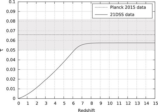
Average Thomson scattering optical depth computed out to redshift z. The simulations are used at z > 6 and we assume identical first hydrogen and helium ionization, as well as instantaneous second helium ionization at z = 3. The history does not depend on the model since they have almost identical ionization histories.
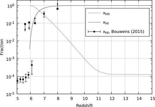
Evolution over redshift of the volume averaged ionized and neutral fraction, compared with observational data. All models share a near identical history (differing only in X-ray production).
3.1.2 Cosmic star formation history
Taking into account the available observational constraints on the cosmic star formation history allows us to break the degeneracy between the escape fraction of ionizing photons and the star formation efficiency (which exists if only the global ionization history is considered). In Fig. 3 we plot the evolution of the SFR density as a function of redshift in the simulations, together with observational constraints derived by Bouwens et al. (2015a). The mean-redshift values and horizontal error bars of the observational points were not computed from the definition of the redshift bins, but instead from the actual mean and scatter of the populations in each bin. To achieve this match we tuned only the star formation efficiency in the simulations.
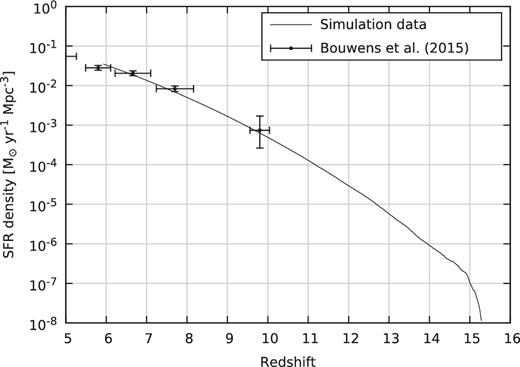
History of the average SFR density in the simulations, compared to observational data. The match was achieved by tuning the simulation parameters. See the main text for the computation of the redshift value and error bars for the observational data points.
3.2 Astrophysical parameters
Modelling the 21-cm signal from the EoR, even with detailed numerical simulations, involves a number of parameters that encapsulate the action of physical processes beyond the scope of the simulation (usually because they operate on scales outside of the range covered by the simulations). Some of these parameters can be constrained by observations as in the previous section while others are relatively free, such as the efficiency of X-ray production at high redshift. Let us review the parameters kept constant in this first version of the data base (possibly to be varied later on) and those that were varied.
3.2.1 Unvaried parameters
As mentioned in Section 3.1, the parameters describing star formation were calibrated to match observational data, and therefore remain unchanged throughout the simulations. Star formation is triggered in gas particles with a comoving overdensity above 100. We use a Schmidt law with exponent 1: |${{\rm d}\rho _{\rm s} \over {\rm d}t} = c_{\mathrm{eff}} \rho _{\rm g}$|, where ρg is the gas density, ρs is the star density and ceff is an efficiency parameter. In the case of an exponent equal to 1, ceff is the inverse of the gas conversion time-scale. This time-scale is set to 2 Gyr in the simulations. Note that the physical meaning of this value should not be overemphasized: it was set such that it satisfied the observational SFR density constraints and, in fact, depends strongly on the chosen density threshold that, in turn, is related to the mass resolution of the simulation. Only the photo-heating feedback, intrinsic to radiative hydrodynamics, is effective: no kinetic nor thermal feedback from SN or AGN is included. The IMF of the star population is chosen to be a Salpeter IMF with lower and upper mass cutoffs at 1.6 and 120 M⊙ respectively. The resulting emissivity and spectral shape in the Lyman lines and ionizing UV ranges are then computed using the procedure described in Baek et al. (2010). The emissivity in the range of the Lyman lines is, in fact, varied as explained in the next section.
To satisfy the observational constraints on the ionization history, the escape fraction of ionizing UV photons was fixed at fesc = 0.2. Note that this quantity refers to the photons escaping from dense structures around the source and below the resolution of the simulation, not from haloes: photons are explicitly propagated and absorbed in resolved structures within the haloes. Thus, while fesc = 0.2 does not depend on halo mass, different behaviour can occur in haloes with different masses, especially towards the well-resolved high-mass end.
Although the emissivity of hard and soft X-rays varies between simulations (see the next section), the spectral shapes do not. Soft X-rays, for example those produced by AGNs, are modelled with a spectral index of 1.6, a lower cutoff at 100 eV and an upper cutoff at 2 KeV. Hard X-rays, due mainly to the contribution of X-ray binaries, are modelled using the spectral properties tabulated by Fragos et al. (2013).
3.2.2 A choice of three-parameter space
In this study, we chose to vary parameters related to the Wouthuysen–Field coupling and the X-ray heating of the neutral IGM. Such parameters crucially determine the duration and intensity of the era in which the 21-cm signal can be seen in absorption against the CMB.
Lyman band emissivity: fα
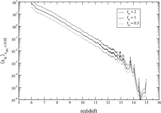
History of the spatially averaged xα coefficient in the neutral IGM (defined as |$x_{\mathrm{H\, {\scriptscriptstyle II}}}<0.02$|), after multiplying by fα but before taking the backreaction into account.
X-ray emissivity: fX
X-ray hard-to-soft ratio: rH/S
This ratio takes the values rH/S = 0, 0.5 and 1. Fig. 5 shows the combined effect of varying fX and rH/S on the average kinetic temperature history of the gas regions with ionized fraction smaller than 0.02. It shows that changing rH/S from 0 to 1 is more or less equivalent, in term of the average temperature, to decreasing fX by a factor of 3. But, of course, it is not that simple, and changing the rH/S value strongly alters the temperature fluctuations. This effect is not negated by adjusting fX in order to keep the average constant.
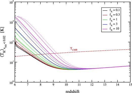
Histories of the average kinetic temperature in the neutral gas (defined as |$x_{\mathrm{H\, {\scriptscriptstyle II}}}<0.02$|) for all the models. The solid lines correspond to models with rH/S = 1, dashed lines to rH/S = 0.5, and dotted lines to rH/S = 0.0. Colour encodes the value of fX, as specified in the label.
3.3 The 21-cm signal
3.3.1 Methodology
3.3.2 The range of predicted signals
The explored parameter values are summarized in Table 1. Since we consider every possible combination, we ultimately explore 45 points (i.e. 45 models) in this three-dimensional parameter space. The resulting global signal histories are presented in Fig. 6. These were computed from the corresponding high-resolution lightcones (see Section 3.4.2) by averaging δTb in each of the 8192 slices (each is perpendicular to the line of sight). The small-scale fluctuations consistent across all models are due to sample variance. Indeed, since we average over a single thin slice, sample variance is much larger than when coeval snapshots are used. Moreover, since all models share the same initial conditions, and all lightcones used for this plot were generated using the same line of sight, ionized bubbles and other such features appear at the same location in each lightcone (hence the consistency in the small-scale fluctuations across the models).
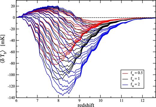
Global 21-cm signal computed from lightcone data for all 45 models. Models are not identified individually, but each group of fixed fα is ordered the same as in Fig. 5 (strong to weak absorption, and weak to strong heating). This figure is intended to give an impression of the range of possible signals. Note that the small-scale fluctuations consistent across models are caused by sample variance in the lightcone.
The explored values for each parameter. Every combination is considered, hence 45 points in parameter space. The definition of the parameters is given in the main text (Section 3.2.2).
| Parameter | Explored values |
|---|---|
| fα | 0.5, 1, 2 |
| fX | 0.1, 0.3, 1, 3, 10 |
| rH/S | 0, 0.5, 1 |
| Parameter | Explored values |
|---|---|
| fα | 0.5, 1, 2 |
| fX | 0.1, 0.3, 1, 3, 10 |
| rH/S | 0, 0.5, 1 |
Fig. 6 is mainly intended to give an impression of the range of possible signals. However, for each value of fα, the specific model for each curve can be determined by looking at the strength of the absorption regime. Indeed, the latter is inversely proportional to the efficiency of the heating, and thus the vertical ordering is reversed from Fig. 5 to Fig. 6. Let us emphasize again that we chose not to vary the source formation history in this first version of the data base. It may be possible to start source formation at higher redshift and rise more slowly while still satisfying the observational constraints. Then the absorption regime would be shifted towards higher z.
3.4 Overview of the publicly available data
3.4.1 Data base web access
The simulated data described below are available at 21ssd.obspm.fr. They are available for download after a simple registration procedure (note that the largest files are 32 GB.). Instructions on how to read the files are provided as well as the source codes used to produce some of the data.
3.4.2 High-resolution 21-cm lightcones
Lightcones were generated on-the-fly while running the simulations. They were made between the redshift of first source formation, z = 15, and z = 6. These lightcones are, in fact, a (large) set of particles with their associated redshift as well as all physical quantities necessary to compute the brightness temperature. The exception is the local Lyman-α flux lightcone. Since the corresponding simulation is run in post-processing and already interpolates between snapshots, the Lyman-α flux lightcone was also built by interpolation of snapshots, 10 Myr apart. The brightness temperature is then computed for each particle and mapped on a 1024 × 1024 × 8192 grid (with the higher dimension along the line of sight) using SPH-like interpolation. The cells have equal δa (or equivalently, δν) along the line of sight, and hence they vary in comoving thickness. The chosen resolution allows for near cubic cells in terms of comoving distance, with sizes close to the average inter-particle distance. A higher resolution would be useful in dense regions, but would produce files with a size unrealistic for standard internet downloads. One lightcone is 32 GB. The lower resolution lightcones, compatible with the expected SKA resolution, are computed by averaging over the high-resolution ones. One high-resolution lightcone is provided for each of the x, y and z observer directions and for each of the 45 models, for a total of 135 lightcones (∼4 TB of online data).
Fig. 7 shows the same lightcone slices for a representative sample of six different models, ranging from those with a strong absorption regime to a very weak one. Of particular interest are the two middle panels that correspond to models with very similar average kinetic temperature histories, but somewhat different levels of brightness temperature fluctuations.
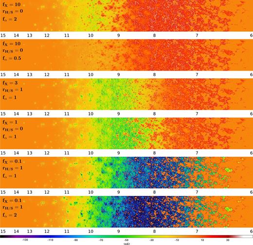
Brightness temperature maps for six models spanning the range of signals in the data base (see labels on the maps) arranged from strongest emission (top) to strongest absorption (bottom). The maps are slices, of a single cell in thickness, taken parallel to the line of sight. They are made using the high-resolution lightcones, and thus have a 1024 × 8192 resolution. Corresponding redshifts are indicated below the maps.
Let us mention that the high-resolution brightness temperature lightcones in the data base contain a small number of cells with very strong emission (>100 mK). These correspond to recombining high-density gas in galaxies, spread into elongated structures along the line of sight by redshift-space distortions. While, in principle, this effect may actually be real and appear in observed data, it operates too close to our resolution limit for us to be confident in its magnitude in our simulations. Data base users may want to filter it out by clipping very high emission values.
3.4.3 SKA-resolution 21-cm lightcones including thermal noise
From the high-resolution lightcones, it is simple enough for future users of the data base to produce lower resolution lightcones, to anticipate SKA tomographic capabilities. Regardless, for convenience we provide the corresponding sets of lightcones with resolutions of 32 × 32 × 256 and 16 × 16 × 128, corresponding to 6.25 and 12.5 h−1 cMpc or (varying) angular resolution of the order of 3 and 6 arcmin, respectively. To produce these, we did not account for the beam shape. We simply computed the average of the high-resolution cells within each low-resolution one.
We provide a data file containing the rms thermal noise level per pixel for the tomographic signal for a range of redshifts and angular resolutions. There are also realizations of the corresponding Gaussian random variables in the form of thermal noise lightcones for the two low resolutions. The thermal noise level was computed using the SKA station configuration described in the SKA-TEL-SKO-0000422 document and thus it accounts for inhomogeneous UV coverage. The code for computing the noise is publicly available in the data base, and survey parameters can be modified at will. The specific parameter used for the above realizations are the following: 1000 h observing time (assuming 8 h runs with the target field always at the meridian after 4 h, which does not account for seasons), a field at −30° declination (compared to the −26|$_{.}^{\circ}$|8 latitude of SKA-Low), and stations of diameter 35 m, each containing 256 dipoles with effective collecting area |$\min (2.56,\lambda ^{2 \over 3})$|. We used |$T_{\mathrm{sys}}=100 + 300 ({\nu \over 150 \, \mathrm{MHz} } )^{-2.55}$| as in Mellema et al. (2013).
In Fig. 8 we show what the brightness temperature maps (sections of the lightcone parallel to the line of sight) look like after typical SKA noise is added. We consider the two resolutions mentioned above (the corresponding range of angular resolutions is shown on the top left of each map). It should be noted that the real SKA survey may produce maps with fixed angular resolution instead. In line with the estimation in Mellema et al. (2013), the ∼3 arcmin resolution maps would not be usable in the case of a low-intensity signal such as in the top panel. In all models tomography becomes difficult at z > 12, unless a strong absorption regime occurs at these redshifts. The resolution required for a reasonable signal-to-noise ratio is typically >5 arcmin (10 h−1 cMpc), which only allows us to map structures of (at least) several tens of cMpc in size. However, keep in mind that the actual SKA field is three-dimensional and will cover a solid angle about 10 times larger than ours. Thus, limitations at small scales will be compensated for by good statistics on large scales, and tomography should still prove a treasure trove of information.
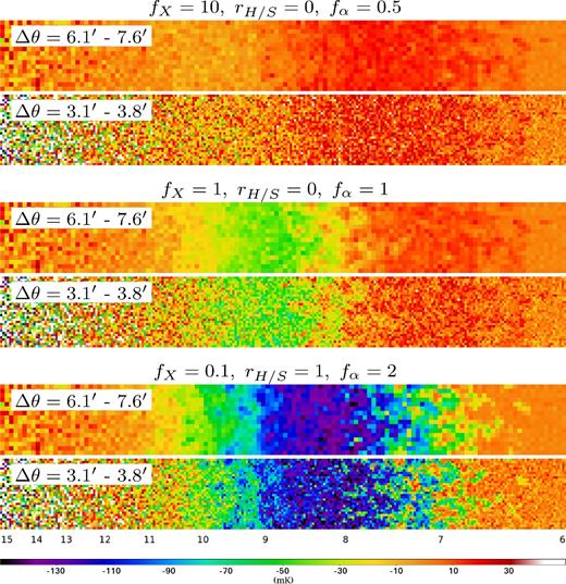
Brightness temperature maps for three models identified by the labels on the maps, at 12.5 and 6.25 h cMpc−1 resolution (the corresponding angular resolution ranges are indicated on the maps.). Thermal noise for a typical SKA survey (see the main text for details) was added to the simulated signals.
3.4.4 Power spectra
We also provide 3D isotropic power spectra computed using the high-resolution lightcones (thus accounting for redshift-space distortion and the evolution of the ionization history). These are formatted as tabulated functions of |$\Vert {\boldsymbol k}\Vert$| and z. The code used to compute the power spectra is available online. A sample of the variety of behaviour for different models is shown in Fig. 9. It should be emphasized that the average amplitude of a given model at fixed z depends strongly on the source formation history. A different history shifts a given signal to a different z. Thus, relying on the amplitude to distinguish between models whose source formation history was keep constant is hardly possible: it is degenerate between different source formation histories. What may be more discriminating is the variation of the power spectrum as a function of the wavenumber: slope, fluctuations, etc. We can also see in Fig. 9 that, while on large scales (|$\Vert {\boldsymbol k}\Vert \sim 0.1$| h cMpc−1) the SKA sensitivity should allow us to easily distinguish between models, the small-scale limit at which thermal noise overpowers the signal depends strongly on the model (and the source formation history). In our exploration of the parameter space, at z = 8 this limit varies by a factor of more than 4. The thermal noise in Fig. 9 was computed using the same survey parameters as in the previous section, a bandwidth of 10 MHz, and a bin width of Δk = k. The code is also available on the data base web site.
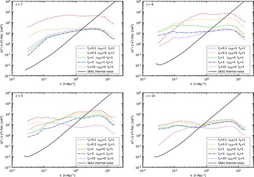
Three-dimensional isotropic power spectra at different redshifts (see labels) for five different models broadly covering the range of simulated signals. The thermal noise for a typical SKA survey is also plotted (see the main text for survey parameters).
The provided power spectra and thermal noise levels can be used as templates. They can also be used as a training set to calibrate semi-numerical signal prediction methods, or to directly develop inversion algorithms requiring a sparse sampling of parameter space (e.g. Shimabukuro & Semelin 2017).
3.4.5 Pixel distribution functions
The power spectrum is a natural by-product of interferometric observations and, being a statistical quantity, can be measured with a good signal-to-noise ratio. It does not, however, contain all the information when dealing with a non-Gaussian signal. On the other hand, tomography does. However, it also contains irrelevant information linked to the phases of the primordial random field (e.g. positions of the bubbles), and suffers from a high level of noise. Different statistical techniques have been suggested to quantify the non-Gaussian nature of the signal. The pixel distribution function (PDF; Ciardi & Madau 2003; Mellema et al. 2006; Harker et al. 2009; Ichikawa et al. 2010; Baek et al. 2010) is a diagnostic rich in information, especially in its redshift evolution. It could be used (but as of yet has not been) as an alternative to the power spectrum in parameter estimation methods (e.g. Greig & Mesinger 2017; Kern et al. 2017; Shimabukuro & Semelin 2017).
In Fig. 10 we present the two-dimensional PDFs (functions of brightness temperature and redshift) computed from the high-resolution lightcones for the fα = 1 models in our data base. We also plot 1- and 3-sigma contour lines, meaning that a pixel chosen at random from the lightcones will lie within these contours with the corresponding confidence levels (we use fractions of pixels defined for a Gaussian distribution.). We can see that both the PDFs and the contours depend strongly on the model, and hence they prove to be powerful discriminating tools, complementary to the power spectra (see Section 4).
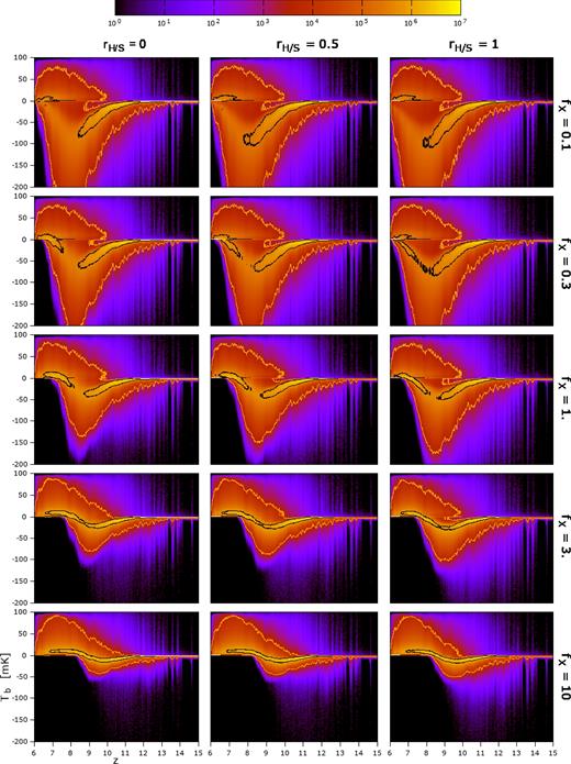
Two-dimensional histograms of the distribution of the 21-cm brightness temperature at different redshifts. This is made using the high-resolution lightcones for all models with fα = 1 (see labels for fX and rH/S values.). This is a natural extension of the PDF defined at a single redshift. The black and orange contours enclose regions where a pixel chosen at random in the lightcone will lie with 1σ (0.682) and 3σ (0.997) confidence. Vertical spikes in the distribution are caused by sample variance.
However, the PDF is more sensitive to thermal noise than the power spectrum. For the power spectrum, long integration times and large survey volumes both help to reduce the thermal noise, and can be independently adjusted. This does not work for the PDF. By definition, each value of the power spectrum is an average of the Fourier mode amplitudes in a shell of fixed thickness. Increasing the Fourier space resolution (larger FoV) increases the number of cells in the shell, and the rms thermal noise on the average of the Fourier mode amplitudes decreases as the square root of the number of cells. In the case of the PDF, increasing the FoV decreases the sample variance, but leaves the thermal noise unchanged in each cell of the tomography. The effect of thermal noise on the PDF is a vertical smearing, as seen in Fig. 11. In this figure we can see the interdependent effects of thermal noise and limited resolution on the two extreme models ‘bracketing’ our range of signals. The thermal noise is computed using the same SKA setup as in Section 3.4.3. As expected, we can see that when decreasing the resolution, we lose much of the faint purple plumes representing the less common brightness temperature values. Thus, the PDF becomes a less powerful diagnostic. Moreover, we can see that at 3 arcmin resolution the SKA thermal noise will be of the same order or larger than the PDF dispersion at all redshifts. At 6 arcmin resolution, the thermal noise remains smaller than the PDF dispersion at z ≲ 10, and much smaller for the strong absorption model at z ≲ 8. Let us finally mention that, when building the PDF from actual SKA tomographic data, the average brightness temperature at each redshift may not be available, removing part of the information contained in Figs 10 and 11.
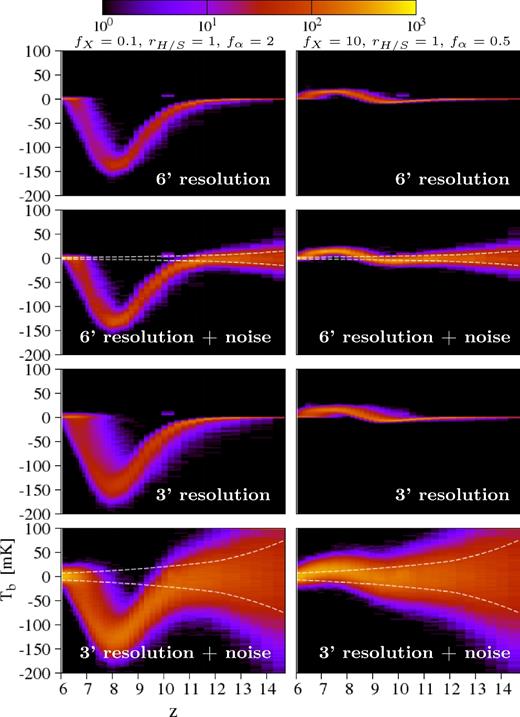
Two-dimensional PDF at two different SKA-like resolutions, with and without the corresponding thermal noise. The left and right columns are for two different models (see label on top): that with the strongest absorption and that with the strongest emission. The dashed line shows the level of thermal noise, which depends on resolution and redshift (see the main text for survey details).
To summarize, while the theoretical PDF may hold as much information as the power spectrum, perhaps even more, it is much more affected by instrumental limitations. We will need observations even deeper than a typically SKA survey to fully uncover this information.
3.4.6 Data available on request
While the spirit of 21SSD is to share data online, this puts a limit on the quantity of data that can be provided. The data base contains less than five TB of data, but the raw output of the simulations is ∼100 TB. For users who would like access to other types of data, and can arrange a reasonable transfer solution, we have the following quantities stored. First, we have coeval snapshots of the simulations every 10, 20 or 40 Myr (depending on the model). These snapshots contain, for each particle, every quantity relevant to the physical processes included in the simulation (position, velocity, density, temperature, ionization fraction, etc.). While the data base offers gridded lightcones of the 21-cm brightness temperature, the corresponding particle-based lightcones are stored with the same quantities for each particle as with the snapshots. Finally, some runtime logs can be inspected to answer specific questions (e.g. the history of the average photon density). What is not available are snapshots of the radiation field. licorice keeps the radiation field information for the last snapshot only (to allow a restart) in order to save disc space.
4 EXTRACTING KNOWLEDGE FROM 21SSD: A FIRST EXAMPLE
The strength of the 21SSD data base is the number of points explored in the chosen parameter space. Quantifying the variety of simulated signals, and assessing our capabilities to distinguish between them, is an important step towards preparing for the analysis of upcoming observations. Working with imaging data to distinguish between models is difficult because they include random information (the specific positions and strengths of sources) that have to be filtered out. Working with the power spectrum or the PDF seems easier: we only need to beat sample variance (which is not fully achieved in our data, but will be with the SKA survey FoV). We will now present a method to quantify the ability of the PDF and power spectrum to distinguish between different models. We will apply it to the noiseless simulated signals, thus quantifying the theoretical discriminating power. Further investigation including thermal noise will be necessary to draw conclusions concerning observing strategies.
4.1 Power spectra comparison
The distance between the power spectra of all pairs of models in 21SSD is presented in the top panel of Fig. 12, normalized by dividing by the average distance. As expected, this distance is largest between the model with parameters [fX, rH/S, fα] = [0.1, 1.0, 2.0] (strongest absorption) and simulations made with stronger heating levels (different values of fX). In general, it is seen that variations between each ‘block’ of simulations made with equal fX are significant. However, within each of these blocks, the variations are weaker. This seems to suggest that using the power spectra to calculate distances discriminates well for fX, but less powerfully for rH/S and fα, especially for high values of fX.
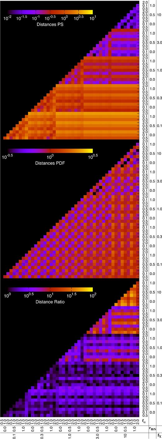
Colour maps of the normalized power spectrum distance (top), normalized PDF distance (middle), and the ratio of these distances (bottom) for every pair of models in the data base (see the main text for the exact definitions). The fX, rH/S and fα values for each individual model can be found on the horizontal and vertical axes. All distances are computed without including any thermal noise contribution to the signals.
4.2 Pixel distribution functions comparison
The PDF proves to be a very different diagnostic, which can be easily seen in the second panel of Fig. 12. First, comparing the PDFs leads to a smaller range of values for distance. This is because each individual PDF has the same L1 norm (regardless of the model there are a constant number of pixels in each lightcone). Therefore, the distance between two PDFs is somewhat more constrained. Conversely, the power spectra can be orders of magnitude lower or higher than others, depending on the efficiency of heating. This difference explains the fact that the normalized power spectra distances fall between three orders of magnitude (10−2 to 101) while the normalized PDF distance only covers roughly one order (10−0.5 to 100.5).
In addition to magnitude, the PDF distances are also very different in form. There is little variation from one 9 × 9 ‘block’ of constant fX values to another, nor between 3 × 3 blocks of constant rH/S, yet there is substantial difference between simulations made with different fα values. This is seen in the different magnitudes of neighbouring pixels.
4.3 Comparing methods
These results provide a first idea of how best to utilize the power spectra and PDF distances to extract parameters. If thermal noise is neglected the power spectrum distance is a better tracer for the fX parameter, while the PDF distance is more suited to determine the fα value. Neither the power spectrum nor the PDF seem especially powerful tracers for the rH/S variable – perhaps somewhat for the power spectrum distances, where slightly different distances are seen between simulations varying only in rH/S. It is possible that a robust parameter extraction system will have to take advantage of both the power spectra and the PDF.
Some very tentative hints towards optimal parameter space sampling are present. The similarity between the fX = 10 and 3 regions of the Distance Ratios (as well as, of course, the power spectrum and PDF distance figures) indicates that a more sparse sampling in this region would have been possible. Using this full distance information to derive an optimal parameter space sampling will be explored further in a subsequent article.
5 CONCLUSIONS
In this work we have presented a publicly available data base of simulated 21-cm EoR signals. High-resolution radiative hydrodynamic simulations (10243 particles in a 200 h−1 Mpc) were performed with the licorice code to predict the signal. The modelling includes radiative transfer in the ionizing UV and X-ray bands coupled to the dynamics, as well as in the Lyman lines (to accurately account for the Wouthuysen–Field effect) in post-processing. With the ionization history unchanged (fitting the available observational constraints) a three-dimensional parameter space is explored which contains 45 different models. This is accomplished by varying the X-ray production efficiency (the fX parameter), the X-ray spectral properties (the rH/S parameter) and the Lyman band photon production efficiency (the fα parameter). Thus, we mainly explore the processes responsible for fluctuations of the 21-cm signal due to heating and Lyman-α coupling. In a future extension of the data base it may be relevant to explore different average ionization histories and ionization fluctuations (within the available observational constraints).
We presented the data products available in the data base, which currently include high-resolution and typical SKA-like resolution lightcones in three directions for each of the 45 models, their associated power spectra and two-dimensional PDFs, as well as thermal noise models for the SKA. The source code used to derive these quantities is also available. We have given some examples of power spectra, compared them to typical SKA noise and studied the two-dimensional PDF in some details, investigated mainly in one dimension in previous studies. We showed in particular that, while the theoretical (noise-free) PDF potentially contains a wealth of information not seen in the power spectrum, taking SKA-like thermal noise and resolution into account substantially decreases the amount of usable information.
Finally, we took a first attempt at quantifying the degree to which different diagnostics respond to model variation. This study is preliminary and needs to also take into account instrumental limitations (primarily resolution and noise). This will be the subject of an upcoming paper.
Acknowledgements
This work was made in the framework of the French ANR funded project ORAGE (ANR-14-CE33-0016). We also acknowledge the support of the ILP LABEX (under the reference ANR-10-LABX-63) within the Investissements d'Avenir programme under reference ANR-11-IDEX-0004-02. The simulations were performed on the GENCI national computing centre at CCRT and CINES (DARI grants number 2014046667 and 2015047376).
We would also like to thank Keith Grainge, whose wisdom set us on the right track when preparing to realistically simulate SKA-level noise.
REFERENCES
