


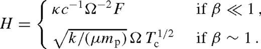
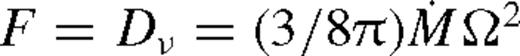
Abstract
Many astrophysical binaries, from planets to black holes, exert strong torques on their circumbinary accretion discs, and are expected to significantly modify the disc structure. Despite the several decade long history of the subject, the joint evolution of the binary + disc system has not been modelled with self-consistent assumptions for arbitrary mass ratios and accretion rates. Here, we solve the coupled binary–disc evolution equations analytically in the strongly perturbed limit, treating the azimuthally averaged angular momentum exchange between the disc and the binary and the modifications to the density, scaleheight, and viscosity self-consistently, including viscous and tidal heating, diffusion limited cooling, radiation pressure and the orbital decay of the binary. We find a solution with a central cavity and a migration rate similar to those previously obtained for Type II migration, applicable for large masses and binary separations, and near-equal mass ratios. However, we identify a distinct new regime, applicable at smaller separations and masses, and mass ratio in the range 10−3 ≲ q ≲ 0.1. For these systems, gas piles up outside the binary's orbit, but rather than creating a cavity, it continuously overflows as in a porous dam. The disc profile is intermediate between a weakly perturbed disc (producing Type I migration) and a disc with a gap (with Type II migration). However, the migration rate of the secondary is typically slower than both Type I and Type II rates. We term this new regime ‘Type 1.5’ migration.
1 Introduction
Understanding the co-evolution of binaries and accretion discs is fundamental in several fields of astrophysics, including planet formation and migration (Goldreich & Tremaine 1980; Ward 1997), patterns in planetary rings (Goldreich & Tremaine 1982), stellar binaries, compact object and binaries involving supermassive black holes (SMBHs).
Despite the long history of the subject, there are no self-consistent analytical models for the co-evolution of binaries and accretion discs, incorporating the fundamental physical effects over the long time-scales on which the binary separation evolves. The standard α-model of radiatively efficient turbulent thin accretion discs (Shakura & Sunyaev 1973) relates the effective kinematic viscosity of the disc to the pressure ν ∝ αp. The viscous evolution of the disc, however, is often modelled without considering the pressure dependence of the viscosity (Lynden-Bell & Pringle 1974). Similarly, models of the gravitational interaction between the disc, which describe the launching of spiral density waves in the disc that remove angular momentum from the binary, also do not account for the tidal heating of the disc and the corresponding feedback on the torque cut-off phenomenon (Goldreich & Tremaine 1980).
The evolution of the circumbinary disc is sensitive to the above-mentioned assumptions, especially when the mass of the secondary is large, and can strongly perturb the disc. For a massive secondary, the tidal torque clears a gap in the disc, and the viscous radial inflow of the gas pushes the object inwards on the viscous time-scale (Type II migration). If the secondary mass, ms, is larger than the local disc mass,  , where Σ is the surface density, then the migration slows down, as the spiral density waves cannot remove angular momentum away from the binary at a rate on which the gas flows in. This leads to the pile-up of gas outside the secondary's orbit, in which the gas density increases by up to a factor B−3/8, where B = md0/ms < 1 and md0 is the unperturbed local disc mass (Syer & Clarke 1995). Once this steady-state level is reached, the viscous gas inflow velocity matches the inward migration of the object (secondary-dominated Type II migration).
In this paper, we focus on such systems, with ms > md0, and point out that the Syer & Clarke (1995) steady-state level of gas pile-up cannot be reached for sufficiently large secondary masses ms ≫ md0, where B ≪ 1. The enhanced viscous dissipation rate (Dν ∝ B−5/8) can increase the disc temperature such that it becomes radiation pressure dominated. The enhanced pressure makes the disc puff up (H ∝ B−5/8), and reduces the relative gap size. Once the gas approaches within a distance less than the scaleheight from the secondary, the torque that the disc exerts on the binary has a cutoff (Goldreich & Tremaine 1980; Artymowicz 1993b, 1993a; Goodman & Rafikov 2001) which limits the migration rate of the secondary. Once the gas enters the Hill radius, it can furthermore flow across the secondary's orbit along horseshoe orbits or accrete on to the secondary. We derive an analytical quasi-steady-state model for the co-evolution of the disc and the orbital migration of the secondary, in which we combine a Shakura & Sunyaev (1973) disc with the theory of the binary--disc interaction by Goldreich & Tremaine (1980) self-consistently. In particular, we adopt the viscosity prescription of standard thin accretion discs proportional to pressure,1 calculate the sound speed and vertical balance including both gas and radiation pressure (pgas and prad), adopt the simple analytical approximation to the angular momentum exchange between the binary and the disc of Armitage & Natarajan (2002), consider the standard viscous and tidal heating of the disc (Lodato et al. 2009), and self-consistently account for the feedback on the pressure, viscosity, scaleheight and the torque cutoff near the secondary's orbit. We generalize the steady-state model of Hourigan & Ward (1984), Ward & Hourigan (1989) and Liu & Shapiro (2010) by self-consistently including variations in the viscosity and pressure caused by the pile-up. We derive azimuthally averaged steady-state analytical disc models which recover the Goodman & Tan (2004) solution for arbitrary β = pgas/(pgas + prad) in the limit that the secondary mass ms approaches zero, but the disc structure is significantly modified by the secondary over multiple accretion time-scales for larger ms.
The disc structure in this overflowing state with a pile-up is intermediate between the weakly perturbed case without a secondary and the case with a gap. Not surprisingly, the migration rate in such an intermediate state, which we label Type 1.5, is significantly different from the corresponding limiting cases of Type I migration and the secondary-dominated Type II migration. The transition between Type I and Type II migration as a function of the secondary mass was previously typically investigated by considering only the change in the surface density due to gap formation, but without investigating the feedback from the changes in viscosity and pressure (Hourigan & Ward 1984; Ward & Hourigan 1989; Korycansky & Papaloizou 1996; Ward 1997; Bate et al. 2003; Crida & Morbidelli 2007). However, simulations show that migration is sensitive to temperature variations and radiation pressure (D'Angelo, Henning & Kley 2003; Paardekooper & Mellema 2006, 2008; Kley & Crida 2008). We derive the Type 1.5 migration rate for the self-consistent radial profile including these effects when the pile-up is significant in an overflowing steady-state disc. As the secondary migrates inwards across the increasingly hotter inner regions of the disc, the gap opening conditions and the migration rate change even if one neglects the feedback on viscosity and temperature due to gas pile-up (Haiman et al. 2009; Kocsis, Yunes & Loeb 2011), but here we show that the changes are significant over a much wider range of masses and radii in the self-consistent model. We discuss migration and gap opening for SMBH binaries in more detail in Kocsis, Haiman & Loeb (2012, hereafter Paper II).
The remainder of the paper is organized as follows. In Section 2, we lay out the basic equations governing the hydrodynamical and thermal evolution of the disc, as well as the migration of the secondary. We solve the equations numerically in Section 3. We then derive an analytical solution in Section 4. We summarize the results, and discuss how they depend on the most important physical parameters, in Section 5. We offer our conclusions in Section 6. A more detailed discussion and the implications for SMBH binary systems are presented in Paper II.
We use geometrical units G = c = 1, and suppress factors of G/c2 and G/c3 to convert between mass, length and time units. Our basic notation for the disc and secondary parameters is depicted in Fig. 1.
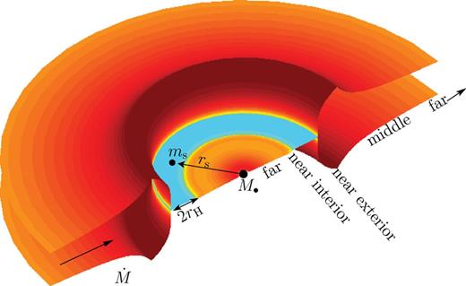
Gas pile-up and overflow in a circumbinary accretion disc with component masses M• and ms, binary separation rs, and accretion rate  . We distinguish five distinct radial zones: an inner and an outer far zone where the effects of the secondary are negligible, an interior and an exterior near zone where the tidal effects are significant, and an extended middle zone with a significant gas pile-up (see Section 4).
2 Thermo-Hydrodynamical Interaction Between A Disc and A Secondary
We examine the evolution of the secondary and an azimuthally and vertically averaged Shakura–Sunyaev disc (i.e. axisymmetric one-zone disc) in local thermal equilibrium. Here we review the basic equations. First, we write down the continuity and angular momentum transport equations including the viscous torque and the gravitational tidal torque of the secondary. The back-reaction of the tidal torque changes the angular momentum of the secondary. The viscous and tidal torques depend on the disc surface density, viscosity and pressure gradient (or scaleheight). We derive the vertically averaged disc structure assuming that: (i) the local viscous plus tidal heating equals the radiative cooling with photon diffusion limited vertical radiative flux (i.e. negligible radial heat transport); (ii) the viscosity is proportional to either gas+radiation pressure (α-disc) or just the gas pressure (β-disc) and (iii) gas plus radiation pressure supports the disc against the vertical gravity. This yields a closed set of non-linear partial differential equations for the disc and the location of the secondary in 1+1 dimensions. We present solutions in subsequent sections below.
2.1 Angular momentum transport


 outside the torque cutoff in Goldreich & Tremaine (1980),
  in Lin & Papaloizou (1986), and f = 10−2 calibrated to match the gap opening conditions in Armitage & Natarajan (2002).3 We adopt a conservative value f−2 ≡ f/10−2 ∼ 1 in our numerical calculations, but keep the f−2 terms general in all of our analytical formulae. Note that practically equation (6) assumes that the tidal torque density ‘saturates’ instead of having a true cutoff near the secondary as long as the gas density is non-vanishing there (Artymowicz 1993b), which accounts for the effects of shocks near the secondary (Goodman & Rafikov 2001; Dong, Rafikov & Stone 2011b; Duffell & MacFadyen 2012).4,5 However, this prescription might be inaccurate for a high-mass secondary forming a gap in the disc, where the tidal torques are due to spiral streams passing near the secondary on horseshoe orbits (MacFadyen & Milosavljević 2008; Baruteau, Ramirez-Ruiz & Masset 2012; Petrovich & Rafikov 2012; Roedig et al. 2012; Shi et al. 2012). We do not consider the torques inside the Hill radius, |r − rs| < rH ≡ (q/3)1/3rs, assuming that gas reaching this region flows in across the secondary's orbit. Outside this region, we use (4), assume that gravity is dominated by M• and the orbital velocity is nearly Keplerian,
  , where
  .
.
 so that
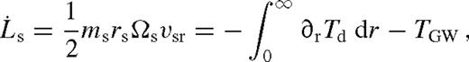
 , the torque from the GWs is given by
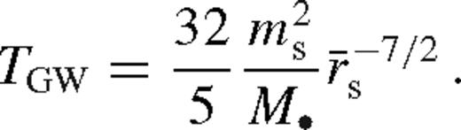
 and
and  so that
  is a constant.6 Note that in general the disc need not be in steady state. However, in many cases the inflow rate of gas may be much faster than the radial migration speed of the secondary |vsr| ≪ |vr|. If this is satisfied in a wide range of radii up to the outer edge of the disc, then the secondary is effectively stationary in the azimuthally averaged picture, and the radial profile of the disc might be expected to relax to a steady state, independent of the initial condition of the disc. We propose that the secondary then migrates slowly through a sequence of quasi-steady-state configurations of the disc with a fixed
  . Then, equation (8) becomes
 is specified for a specific disc model.
2.2 Boundary conditions
We distinguish two types of inner boundary conditions corresponding to whether or not the perturbation is strong enough to lead to a truncated disc with a wide hollow circular cavity. Here, ‘wide’ means wider than the Hill radius (see below).
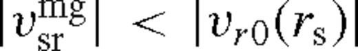
- (I)If Σ(r) ≠ 0 all the way to the innermost stable circular orbit rISCO of M• (i.e. the disc does not have a cavity), we require a zero-torque boundary condition (Novikov & Thorne 1973; Penna et al. 2010; Tanaka 2011; Zhu et al. 2012),Starting with this boundary condition, we obtain, among other properties of the steady-state disc, the gas velocity profile vr(r). As stated above, if this inflow velocity is much faster than the migration velocity of the secondary over a large range of radii, then one might expect that the disc approaches this steady-state configuration, independent of the initial condition. In the opposite case, the steady-state assumption may be violated by the time-dependent migration of the secondary. As we will show, the steady-state solution with a fixed12

 requires a large build-up of gas outside the secondary for the viscosity to overcome the tidal barrier of the secondary. We refer to these solutions, in which the disc is not truncated outside the secondary, as ‘overflowing’.
 - (II)If the tidal torques dominate over the viscous torques near the secondary, gas is expelled from the region near the secondary and a wide gap forms. Assuming that the characteristic radius rg, where the tidal torque is exerted on the disc near the edge of the gap, tracks the inward migration of the secondary with rg = λrs where 1 < λ ≲ 3 is a constant, we require that the gas velocity at that radius satisfies (Syer & Clarke 1995; Ivanov, Papaloizou & Polnarev 1999)Note that λ is not specified by hand ab initio; it is found by assuming steady state in our solutions below. This condition can be understood intuitively, since the secondary cannot ‘run away’ and leave the outer disc behind (if it did, it would cease to be able to torque the disc and would have to slow down). Likewise, the gap edge cannot get closer to the secondary (if it did, gas would pile-up and the gap would eventually close). Although the disc is not in steady state near its boundary, we assume13

 at r > rg (see discussion in Section 4.1.4.).

Note that here and throughout the paper, by ‘gap’ we refer to situations where the gas density becomes effectively zero outside the secondary, such that the inflow of gas from the outside pushes the secondary inwards according to (13). In these cases, we assume that inflow across the orbit is insignificant, and in particular, we neglect torques from the gas interior to the orbit. In our calculations, a gap is effectively a hollow circular cavity in the disc, which is supported by the tidal torques of the secondary. However we emphasize that we do not rule out the presence of a local density decrement, resembling an annular gap, with a significant mass flux across the gap.
In practice, we attempt to find a solution with either of the above two boundary conditions, and then check whether the solution is self-consistent. By construction, only one of the two boundary conditions will lead to a self-consistent solution as confirmed below.
2.3 Physical conditions in the disc
Next we derive H(r) and ν(r) which appear in the tidal and viscous torques in equations (3)–(5).
2.3.1 Vertical balance
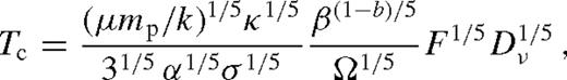
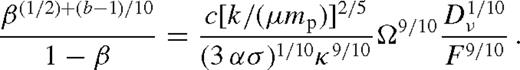
 is the local midplane sound speed and p = pgas + prad is the pressure due to the gas and radiation,7pgas = ρkTc/(μmp),
  , where Tc is the central temperature, a = 4σ/c is the radiation constant, σ is the Stefan–Boltzmann constant, mp is the proton mass and μ = 0.615 is the mean particle mass in units of mp. Since ρ = Σ/(2H),
  so that cs = 2p/(ΣΩ). The pressure can be expressed as p = prad/(1 − β), where β = pgas/p. If photons are transported to the surface by diffusion, then the mean radiation flux is
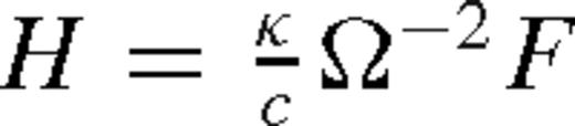
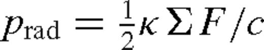 , so that cs = κc−1F Ω−1(1 − β)−1, and we have
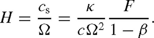
2.3.2 Viscosity
 , where b = 0 or 1, respectively, and α is a constant parameter (Shakura & Sunyaev 1973; Sakimoto & Coroniti 1981), implying that
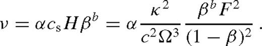
2.3.3 Local thermal equilibrium
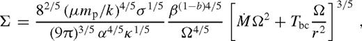
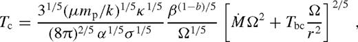
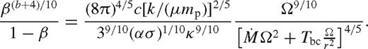
2.3.4 Summary
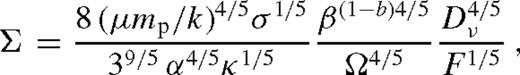
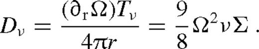
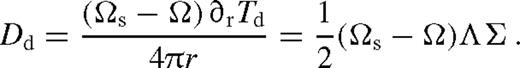
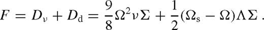
 , we recover the solution of Goodman (2003) up to a constant of the order of unity.10
More generally, equations (16), (21) and (23), along with the definition of Dν and F in equations (18) and (20), and the angular momentum flow equation (11), provide a closed set of equations for the stationary disc, valid throughout the gas and radiation-pressure dominated regions for α and β discs. The solution is self-consistent if for all r, the disc is thin (H < r), the radiation flux is sub-Eddington ( ), the radial accretion velocity is subsonic (
 ), radial heat transport is negligible, the self-gravity of the disc is negligible and the disc is stable against fragmentation (Q = csΩ/(πGΣ) ≥ 1), the disc is optically thick (τ = κΣ/2 ≥ 1) and the boundary conditions are satisfied (implying in particular that vsr ≪ vr across a wide range of radii for overflowing solutions; see Section 2.2).11 We verify that these conditions are indeed satisfied for the overflowing solutions given below.
3 Disc Structure - Numerical Solutions
First we generate numerical steady-state solutions for tidally and viscously heated discs assuming that the migration rate is much smaller than the radial accretion velocity in the disc. These numerical solutions are useful to verify the detailed analytical estimates presented in the following section.
We proceed along the following steps.
- (i)
Obtain the ratio of gas to total pressure, β = β(r, Dν, F), by inverting equation (23). A unique solution is guaranteed by the intermediate value theorem, since the left-hand side is a monotonic function of β, mapping 0 < β < 1 to all positive real numbers, while the right-hand side is positive and independent of β.
- (ii)
Substitute the solution for β in equations (16) and (21) to obtain H(r, Dν, F) and Σ(r, Dν, F).
- (iii)
Substitute β, H and Σ in the definition of F in equation (20) to get an equation between F and Dν for fixed r and rs. Invert this relation to find F(r, rs, Dν). Similar to step (i), one can show that the solution exists and is unique.
- (iv)
Using equations (18) and (19), obtain the function
 .
. - (v)
Substitute into equation (11) to obtain an expression
 for a fixed
  . Solve this differential equation for Tν(r, rs).
 - (vi)
Substituting back into Dν and F, equations (18) and (20) and the formulae of step (ii), to get Σ(r, rs), Tc(r, rs) and H(r, rs).
 , which leads to the Shakura–Sunyaev disc. If q ≪ 1, then the secondary creates a small dip in Tν(r) in its neighbourhood, where the depth of the minimum increases with q. For larger q, Tν(r) becomes very small positive approaching the secondary from downstream, and the surface density approaches zero. In this regime, tidal heating dominates over viscous heating, and H > |r − rs|, implying that the pressure gradient shifts the torques out of resonance, and the torque is suppressed according to equation (5). Since the adopted torque model is valid only outside the secondary's Hill radius, we stop the calculation at rs − rH, and restart it at ri = rs + rH assuming that12
The solution is approximately self-consistent if the migration rate is slower than the radial gas velocity outside the secondary. However, if this is not satisfied, a cavity opens and the disc becomes truncated. In this case, we seek a different solution in step (v), which satisfies the boundary condition in equation (13). This is possible by increasing ri in equation (25) where Tν(ri) ≈ 0, until equation (37) is satisfied. Here ri can be identified as the truncation radius at the inner edge of the disc. We distinguish the characteristic truncation or gap radius to reside at rg where the tidal effect is exerted on the disc, more specifically the boundary where the tidal torque density becomes subdominant and use rg in the boundary condition, equation (37).13 The surface density increases rapidly within ri < r ≲ rg, has a maximum and decreases thereafter. We assume that the disc is truncated interior to ri if a gap forms with ri > rs + rH.
4 DISC STRUCTURE - ANALYTICAL SOLUTIONS
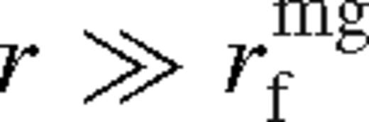
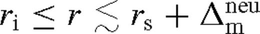
Here we derive an analytical solution to the non-linear equations in Section 2. Such solutions can be derived asymptotically far from the secondary or near the secondary, where either the tidal torque or the viscous torque dominates, or where the angular momentum flux is negligible. We therefore distinguish the corresponding far, middle and near zones (see Fig. 1). The far zones are well inside and well outside the secondary, where the effects of the secondary are negligible. The middle zone is the region outside the secondary where the tidal effects (i.e. torque and heating) are locally negligible compared to the viscous effects, but where the gas pile-up is significant and the disc profile is modified. The near zones are just inside and just outside the secondary's orbit, where the tidal effects of the secondary dominate over the viscous effects. We restrict the near zone to outside the Hill radius, where the adopted tidal torque formula is valid. In addition to providing a basic understanding of the disc structure, the approximate analytical solutions allow us to infer the migration rate of the secondary.
To keep track of the approximations and notations introduced for the various zones below, we provide Table 1 for convenience. Note that the far/middle/near zones divide the disc into five radial slices, and the asymptotic behaviour further depends on whether the disc becomes truncated forming a wide gap (in the middle zone) and whether the torque saturated by the condition on the radial distance from the secondary is δr ≡ r − rs < H (in the outer near-zone). Each row in the table corresponds to one of these disc regimes, discussed in a corresponding subsection below, and shows which terms are relevant in equation (11). The subdominant terms are marked with a ‘0’. The column with Tν shows functions we introduced related to the viscous torque, and  shows the scaling of the specific tidal torque in equation (5).
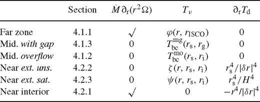
Approximations and notations for the various radial zones in the disc used in Section 4
In the following we mostly focus on β-discs (i.e. b = 1) and examine both radiation and gas pressure-dominated discs, but it is straightforward to derive analogous formulae for α-discs in the same way. We also note that in the radiation-pressure-dominated regime, the viscosity of α-discs is larger by a factor of pgas/(pgas + prad) = β−1. This would generally lead to stronger overflows for a smaller gas pile-up, and the cavity would close for a wider range of parameters than we find below for β-discs.
4.1 Far and middle zones

 ) and the middle zone (
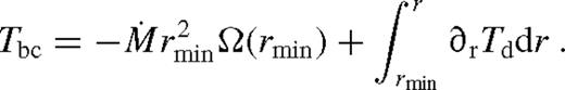
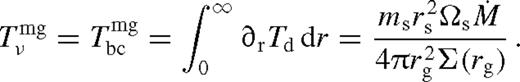
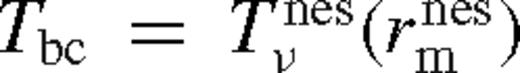
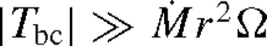 ). The far zone can be either well inside or far outside the secondary's orbit, but the middle zone is always outside. Well inside the secondary, the second term can be neglected in equation (32), and well outside of it, the second term dominates and the integration domain can be extended to ∞. In both cases, Tbc is independent of r.
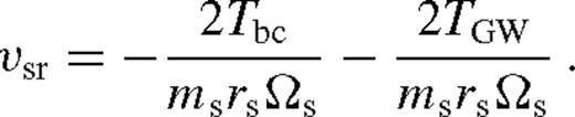
4.1.1 Far zone - unperturbed disc
 . Substituting into equations (27) and (28) gives Dν and F. Plugging in equations (8), (16) and (21)–(22) leads to the standard Shakura & Sunyaev (1973) solution
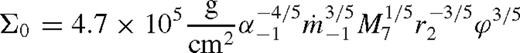

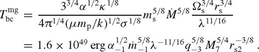
 ,
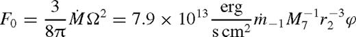
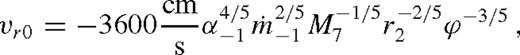
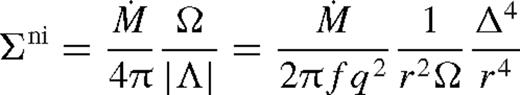
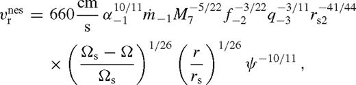
,  is the Eddington accretion rate for 10 per cent radiative efficiency, q−3 = q/10−3, M7 = M•/107 M⊙, rs2 = rs/102M•, and we introduced

 .
.4.1.2 Middle zone
 , where the steady-state perturbation to the torque is significant. In terms of the dimensionless torque barrier,
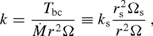
 of the middle zone, where the disc transitions to the far zone. From equation (41),
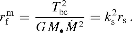
Equations equations (43)–(47) represent a disc with negligible inflow of angular momentum but an inner boundary condition with a large viscous torque, corresponding to the torque barrier. Such solutions are often (somewhat misleadingly) referred to as a decretion disc (Pringle 1991; Lodato et al. 2009). To avoid confusion, we emphasize that there is accretion (i.e. inflow) in this region, too, with a fixed  . However, the radial accretion velocity is greatly reduced, while the surface density, temperature and scaleheight are all greatly increased, relative to an accretion disc around a single compact object.
So far in this subsection, we have derived a solution for an arbitrary torque barrier or k, without specifying its value. In general, k is given by equation (32), which depends on the tidal torque in the near zone. Thus, to complete the derivation of the disc structure in the middle zone, we are first required to obtain the disc structure in the near zone (which we will do in Section 4.2). However, in the case of the steady-state cavity, the particular form of the boundary condition allows us to directly infer k, independently of the near zone, up to a factor λ of the order of unity, which we show next.
4.1.3 Middle zone - steady-state disc with a cavity

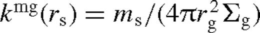 is the ratio of secondary mass to the accumulated local gas mass.14 The only free parameter in this zone is λ, which we determine explicitly in Section 4.3.2..
 , kmg ≫ 1 and equations (43)–(47) give
 , kmg ≈ 0, and the disc approaches the unperturbed solution given by equations (34)–(38). In the transition zone, between the middle and far zones,
 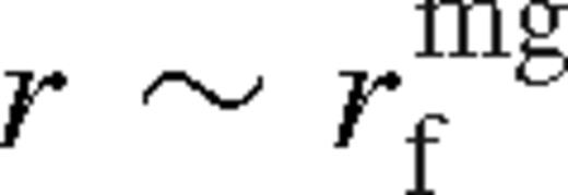 , one needs to use equations (43)–(47) with k = kmg (equation (52)).
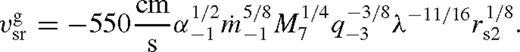
 , in equation (37). This is referred to as disc-dominated Type II migration, which is appropriate if the secondary mass is smaller than the unperturbed local disc mass
 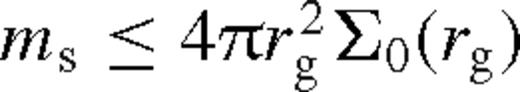 (or equivalently kmg ≥ 1), but large enough to open a gap.
It is interesting to note that the structure of the middle zone does not depend explicitly on the tidal torque model,  (in particular Λ or the f2 parameter in equation (5)); the dependence is implicit and arises only by fixing the value of λ. Physically, while the tidal torques are negligible in this region, the effects of the tidal torques are still communicated to the region by setting an effective hydrodynamical boundary condition. We determine λ in Section 4.3.2. and find that, in fact, it only weakly depends on
  .
.
4.1.4 Consistency of steady state

 is fixed near the gap edge to be a constant fraction of the Eddington value, the true accretion rate
  at larger radii must be larger, to supply material for the increasing gas density. Conversely, if
  is fixed at large radii, then it becomes smaller approaching the gap edge. Such non-steady-state solutions have been derived by Pringle (1991) and Ivanov et al. (1999) by solving the non-linear diffusion equation (7)for a fixed outer boundary condition, assuming that the viscosity can be expressed as ν = kΣarb where k, a and b are constants. In particular, Ivanov et al. (1999) derived a non-steady, but self-similar solution. In that solution, the migration is slower, and the angular momentum flux is lower, compared to the Syer & Clarke (1995) steady-state solutions with a fixed
  for the same binary and disc parameters (Syer & Clarke 1995). The quasi-steady migration rate and brightening factors for a truncated disc with λ > 1 are intermediate between the Syer & Clarke (1995) and Ivanov et al. (1999) solutions.
 and
and  . This sets a maximum limit for the dimensionless angular momentum flux ks. For a β-disc, this implies
An important qualitative difference between the overflowing model presented here and the Syer & Clarke (1995) model for a truncated disc is that γΣs > 0 for the former as we show below. In contrast, in the overflowing case, the excess surface density and the dimensionless angular momentum flux ks in the middle zone both gradually decrease during the inward migration of the secondary. Thus, the excess surface density diffuses radially outwards. If ks < ksmax then the diffusion is sufficiently fast to reach a global quasi-steady state throughout the middle zone. If this is not satisfied, then the outer parts of the middle zone cannot respond as quickly as the object moves inwards and the structure of the disc in these regions will depend on its previous history. However, since the viscous time-scale is always much smaller than the migration time-scale in at least the inner parts of the middle zone, the local disc structure of the overflowing solution might approach an approximate steady state there with a constant  even if ks ≳ksmax. The migration rate of the secondary depends on the near zone of the disc, which is expected to remain insensitive to perturbations in the outer parts of the middle zone in an overflowing disc.15 We leave a detailed investigation of the time-dependent overflowing solutions to future work (Salem et al., in preparation).
4.2 Near zone
Now let us consider the regions near the secondary where the tidal torque and heating are important. We discuss steady-state solutions inside and outside of the secondary's orbit, in turn, without and then with a circular cavity. Deriving the physical properties of the disc in this region is useful to provide an estimate of the torque barrier, Tbc, at the interface between the near zone and the middle zone. As explained previously, the torque barrier sets the overall scale of the physical properties in the middle zone, as well as the migration rate of the secondary. We therefore first compute the value of the torque barrier for an overflowing disc, as well as for a disc with a wide gap. In the latter case, we then compare the value with the torque barrier in the middle zone derived above (equation (51)). By equating the two, we can estimate the gap size (i.e. λ), and obtain the conditions for gap opening and closing.
4.2.1 Inside the secondary orbit


 . The viscous torque then follows from (18). To first beyond leading order, for b = 1,
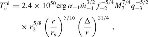
 exhibits a sharp cut-off near the secondary.
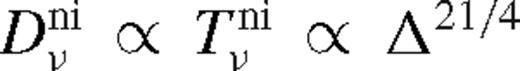 which implies that
 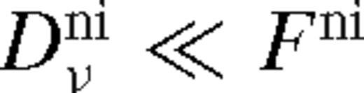 is indeed satisfied for sufficiently small Δ. Coincidentally, the assumption in equation (62) is satisfied within a distance Δni from the secondary, where


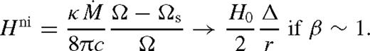
It is remarkable that for a fixed  , the fractional perturbation to the surface brightness and the radiation-pressure-dominated scaleheight are universal in this region, independent of the binary and disc parameters. This property is general for an arbitrary torque or viscosity model in radiatively efficient steady-state discs. The surface density in this regime is also independent of the viscosity model but it is sensitive to the torque model: it is set to ensure that the tidal torque matches the angular momentum flow associated with
  . The original value of the surface density is suppressed by a factor proportional to q−2Δ. These solutions are valid only for discs with relatively large secondary masses, such that Δni > rH, but in which there is gas inflow across the secondary orbit.
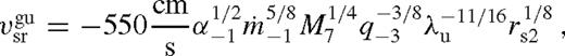
4.2.2 Outside the secondary - unsaturated torque


 depends on radius only through ζ; it increases monotonically and approaches a constant value, which depends very sensitively on Δi/rs. In practice, one might expect

 . We substitute
  from equation (78) utilizing (80) and get
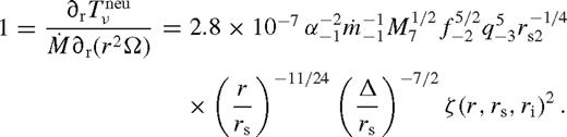
 . While this equation of a single variable can be easily solved numerically for
  for any fixed rs and Δi, we may derive an analytical approximate solution as follows. Assuming
  , ζ is close to its asymptotic maximum, which implies
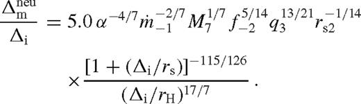
 ,
, 
 as
as  . We find that
  is a slowly decreasing function of Δi, which varies between 1.55 and 1.4 for 0 < Δi ≲ rs.
 , the interface between this region and the middle zone, we must set
  . Based on equations (84) we may use
 (strongly perturbed solution), but not too large so that H < r − rs. We discuss the solutions if the latter condition is violated in Section 4.2.3. below. Comparing equations (40) and (86) shows that the minimum mass ratio to cause a significant gas buildup with unsaturated torques:
 . We do not show these more general but more complicated expressions here.
We note that the results in this section are sensitive to Δi if different from rH, which sets the distance at which the gas can flow in across the secondary's orbit without significant resistance. While Δi ∼ rH is reasonable based on the horseshoe orbits in the restricted three-body problem, we keep it as a free parameter in the following.
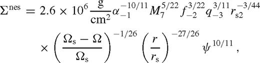
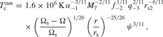
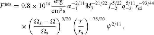
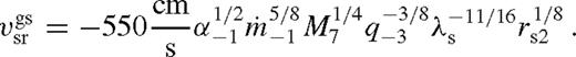
4.2.3 Outside the secondary - saturated torque
Here we again assume that (75)–(76) hold, but now examine the case of much higher secondary masses, where the scaleheight is increased so much that H(r) > r − rs and the tidal perturbation enters the torque cut-off regime. We make the simplifying assumption here that H(r) > r − rs holds throughout the near zone so that the tidal torque in equation (5) does not alternate between saturated and unsaturated. It is straightforward to obtain more general solutions, but we find this exclusively saturated or unsaturated assumption to be an excellent approximation in most cases.
Due to the large torque barrier and tidal heating, the disc in this region is typically radiation pressure dominated, and we accordingly assume β ≈ 0 for the analytical solutions below.
 and
and 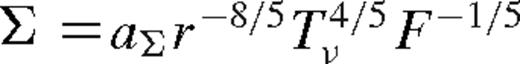 for b = 1, where aΣ is a constant. Substituting into equation (76),
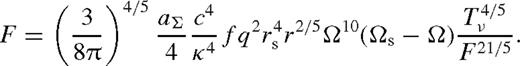
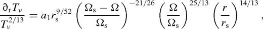
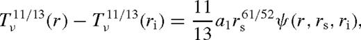
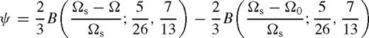

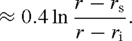
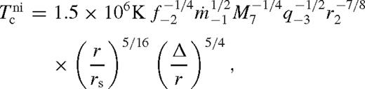
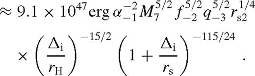
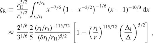
 is the incomplete beta function, and the last two lines are simple approximations, typically accurate to within 15 per cent. We can now use equations (18) to get Dν. For Tν(ri) ≈ 0, after substituting the value of a1, equation (98) yields
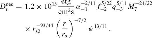
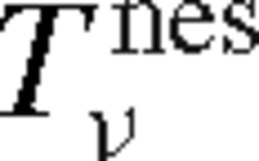
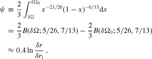
 depends on radius only through ψ. Close to the inner boundary of this region ri, it grows quickly with δr/r and saturates to a constant at δr/r ∼ 1. This can be understood, since this solution neglects angular momentum flow, the viscous torque is equal to the integrated tidal torque density, and the latter has a cutoff at δr/r ∼ 1. We can verify that
  is indeed satisfied in this region (cf. equation (40)) and so the first assumption, equation (75), and Tν(ri) ≈ 0 are well justified.
Can we use the asymptotic maximum of  as an estimate of the torque at the outer boundary of this region to estimate
  in the middle zone of an overflowing disc? In many cases no, because the disc transitions to the middle zone much closer δr ≪ rs, implying that the torque at the outer boundary of this region can be much less than its asymptotic maximum. The outer boundary of this region is where H = r − rs. To figure out exactly where this happens, we proceed to determine the disc structure in this region.

 near the secondary since
  scales with a higher power of ψ. Σ and Tc have a maximum, vr decreases and becomes practically constant, while H slowly increases in this regime.
 , is where18
 as an approximation to the transition radius to the middle zone. After substituting equation (108), equation (109) is a non-linear algebraic equation for
  . While it is easy to solve it numerically for any choice of parameters, it is still useful to derive approximate analytical solutions. We find the following method yields results that are accurate within 20 per cent for a wide range of parameters. Use (100), expand Hnes to second order in
  , use (1 + ax) ≈ (1 + x)a for small x and 1 − xa ≈ −aln x for small a. This gives an approximate relation
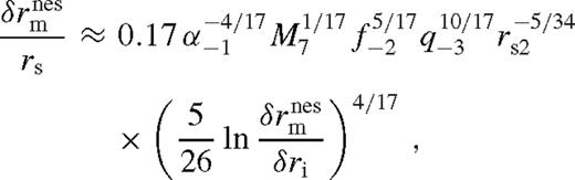

 depends logarithmically weakly on the disc parameters (Corless et al. 1996), in practice
 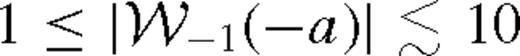 for 10−4 ≲ a ≤ 1/e = 0.368. Here a ≤ 1/e is required for this solution to exist, implying that q and rs have to be sufficiently large and small, respectively. In the opposite case, the torque is unsaturated (Section 4.2.2).
4.3 Transition between near and middle zones
4.3.1 The case with overflow
 . Otherwise, if it is saturated, then we set
 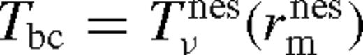 . Matching the middle and near zones at
  assumes that Tν does not grow substantially in the transition region between the saturated near zone and the middle zone, i.e. outside of
  but within a radius where the tidal effects are still non-negligible. We find this approximation to be better than 10 per cent. Thus, to match the torque at the outer boundary of the near zone and the inner boundary of the overflowing middle zone, we combine the saturated and unsaturated cases as
 and
and  are given by equations (86) and (114). If this satisfies
 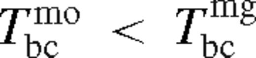 for δri = rH (see equation (51)), then the satellite migration velocity is less than the gas bulk local inflow velocity, and the overflowing steady-state solution is self-consistent. In the opposite case the disc forms a gap with δri > rH.

 (see discussion following equation (91)), peaks sharply near
  . We find that the integrated flux from within a ring of width 0.5 rH is approximately
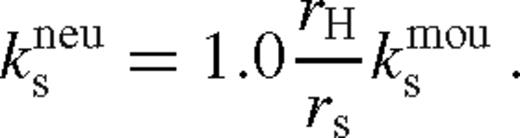
 . We assume an effective radial width
  given by equation (110). From equations (16) and (109), assuming a radiation pressure dominated near zone, the dimensionless angular momentum flux of the near zone relative to the unperturbed disc is
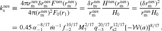
 , we conclude that the luminosity of the saturated near zone can exceed that of the middle zone by a factor between ∼ 3 and 10 for q ∼ 0.1.

4.3.2 Disc with a cavity
Let us next turn to the case with a gap. We determine the radial distance to the outer edge of the gap, λrs, here by requiring that the migration velocity matches the rescaled gas inflow velocity in the middle zone as stated in the boundary condition, equation (13). With λ in hand, equations (53)–(57) determine the disc parameters in the middle zone. The solution is different when the tidal torque is unsaturated near the inner edge and when it is saturated, which we discuss in turn below.
 in equation (48), and substitute equation (80), and eliminate ζ using equation (87). This gives


 ’ subscript is introduced to distinguish the case with unsaturated torques.
 in equation (13) where
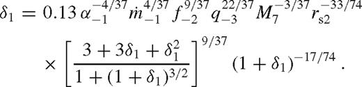
  marks the edge of the near zone according to equation (109), so that λ = 1 + δ1 where
  . Combine equations (107)–(109) to eliminate ψ(r1) from the bulk gas velocity at r1
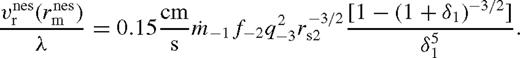
 in equation (48), eliminate
 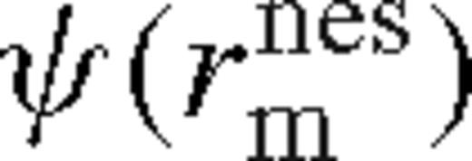 from equations (102) and (109), we get
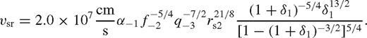


These estimates depend on the somewhat arbitrary definition of λ that we have adopted in the two cases. In the unsaturated case, we have identified it with the outer edge of the transition region between the near and middle zones, where  , while in the saturated case, we considered it to be the inner edge of the transition region, where H = r − rs. While these conventions could be modified, they do not affect the overflowing solution. They do, however, influence the secondary orbital radius where the gap closes, which we discuss next.
4.4 Gap opening and closing
The previous sections define the disc uniquely, which constitute the solution to the basic equations of Section 2. By looking at the solution, we can identify cases where a cavity is kept empty in steady state or when the disc overflows.
 or
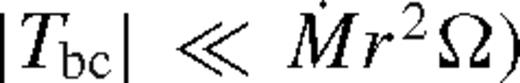
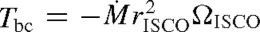
or  , is a monotonically decreasing function of ri. Thus, if the disc is truncated, then the viscous torque at any radius in the near zone is decreased relative to its value for an overflowing disc, ri = rs + rH (equation (82)). This shows that the state of the disc is uniquely determined by the smallest torque barrier,20Tbc, or equivalently, the smallest dimensionless angular momentum flux:
 corresponds to the standard case with a wide gap, with the secondary exhibiting Type II migration. If
  , then the gap edge is located within a scaleheight in the near zone so that the torque cutoff limits the tidal torques, but they can nevertheless support a gap against viscosity as the secondary migrates inward. However, if
  , then the saturated tidal torque becomes smaller than the viscous torque all the way to the Hill radius, and the cavity refills. Finally, if
  , then the disc reaches the Hill radius and overflows already while the torques in the near zone are still unsaturated.
 and
and  are given by practically the same formula, up to an order-of-unity factor of λ. This corresponds to the case of secondary-dominated Type II migration (Syer & Clarke 1995). The migration rate in the overflowing case is
  or
or  for unsaturated or saturated torques. Here the disc is still strongly perturbed, but gas inflow across the orbit limits the efficiency of migration. The disc structure in this new regime is intermediate between a disc with an empty gap (normally associated with Type II migration) and a weakly perturbed disc (Type I migration). Although the migration speed in this regime is slower than either in standard Type II or Type I migration, we refer to this regime as ‘Type 1.5’.

We discuss the gap opening and closing conditions in more detail in Paper II, where we contrast them explicitly with the standard expressions widely used in the literature, and also compare Type 1.5 migration to the previously known Type I and II cases.
5 RESULTS AND DISCUSSION
We have derived analytical solutions to the disc model in different radial regions, where either the tidal, the viscous torques, or the angular momentum flux is negligible relative to the other two terms in equation (11). In particular, we have identified the far zones, either well inside or outside the secondary's orbit, where the effects of the secondary are negligible, the exterior middle zone, where the disc structure is greatly modified but where the tidal torque and heating are locally negligible, and the near zones just inside or outside the secondary, where the tidal effects dominate.21 We distinguish two cases in the middle zone, depending on whether the disc has a gap (i.e. the disc is truncated well outside the Hill radius) or if the disc is overflowing across the secondary's orbit. We also distinguish two cases in the near zone outside the secondary's orbit, depending on whether the tidal torque from the binary is saturated (i.e. whether the location of the cavity edge falls within a scaleheight H from the secondary). Furthermore, we have investigated asymptotic results for gas and radiation pressure-dominated cases.
Distinguishing all of the above cases allowed us to adopt separate approximations, each valid in the corresponding regime, and to derive analytical results to the perturbed accretion disc interacting with the secondary. We further used this to estimate the migration speed for the secondary.
In this section, we collect all of the resulting analytical solutions for the most important disc parameters in the various zones, and present them in a form suitable for easy use. We refer the reader to Paper II for physical interpretations, and discussions on possible implications of our results for real binary systems.
5.1 Disc model

 denotes an extra function of the parameters
  . Note that
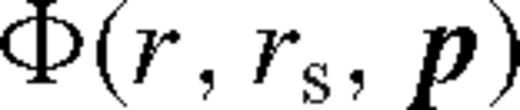
  are the usual parameters of a standard solitary accretion disc; q and f represent the mass ratio and the normalization of the azimuthally averaged tidal torque (see equation (5)). The −N index denotes normalizing with 10−N, e.g. q−3 = q/10−3. The C prefactor, ci exponents and the Φ function in equation (138) are given in Table 2 in the different zones and cases for β-discs (i.e. ν ∝ pgas). For β-discs, many of the physical parameters, including the surface density, Σ, and the central temperature, Tc, are independent of whether gas or radiation pressure dominates. This, however, is not true for the scaleheight, where we quote results in both regimes, labelled with a ‘gas’ or ‘rad’ subscript.
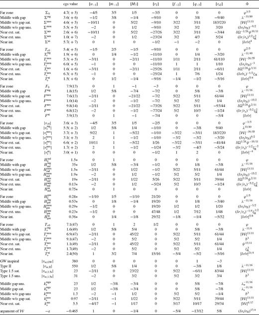
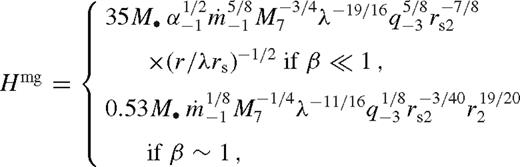
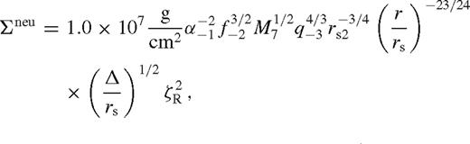
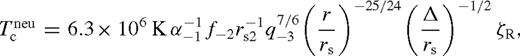
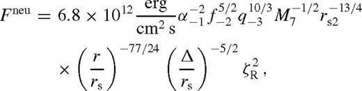
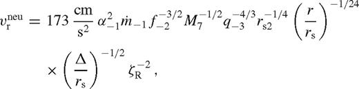
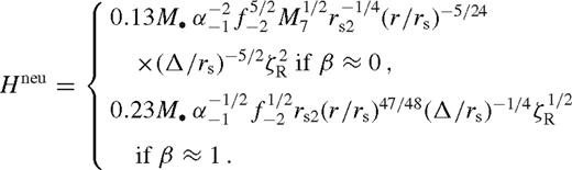
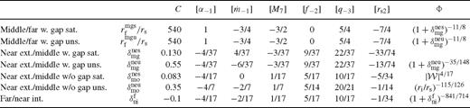
Pre-factors and exponents in the analytical disc model in different zones, C and ci in equation (138). The third column is in cgs units except where marked by * (where it is in units of GM•/c2). Columns 4–10 are exponents; the last column is the extra multiplicative function (see text). The last two block of parameters show the migration rate of the secondary and other useful parameters
 in equation (138). Here we introduced the following notation:
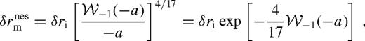
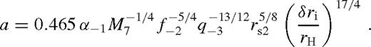


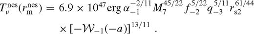
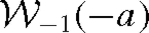
 is the Lambert W-function, the branch defined on the negative real axis, evaluated at −a given in the last row of Table 2. Typically,
  . The approximations shown for ψ and
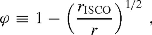
  are better than 20 per cent. Here, rISCO is the innermost stable circular orbit near the SMBH [i.e. 6 M• (1 M•) for a non-spinning (maximally spinning) SMBH)], rH = (q/3)1/3rs is the Hill radius, ri marks the radius at which the viscous torque becomes very small outside the secondary's orbit for which we use

We collect the formulae for the transition radii separating different radial zones and physical regimes in Table 3. We label  , where
  marks the radius of the interface between zone a and b. For example,
  is the transition between the middle zone and the torque-saturated exterior near zone if there is a wide gap, which also sets the truncation radius scale λs in equation (140).
Transition radii between different zones relative to the secondary orbital radius, rs. Here  is the radius at the interface between zone a and b,
  , and
, and  . Different columns show the constant prefactor and exponents in equation (138) as in Table 2
The state of the disc and the migrate speed of the binary are directly set by the dimensionless angular momentum flux ks. If ks =[ ]
] , then the disc is in the [un]saturated overflowing state, whereas if ks =[
 ]
] then it is in the [un]saturated state with a wide gap. These four possibilities are indicated in Table 2. The appropriate choice of ks also determines which case in Table 2 is to be used in the middle zone for the other parameters (‘mou’, ‘mos’ or ‘mg’), and in the near exterior zone (‘neu’ or ‘nes’).
Thus, the ‘phase space’ of solutions consists of four regions.23 The transition between two different solutions, with or without wide gaps, corresponds to the parameters for which  or
or  . Our hypothesis is that this must represent a physical transition in the disc+binary system, as the secondary migrates inwards from large radius. Initially, a central cavity is created, and the outer edge of the cavity lies far from the secondary's orbit. However, as the secondary migrates inwards, the distance between the cavity edge and the secondary shrinks (at least when measured in units of the Hill radius of the secondary). This may happen both because the viscosity increases as the pressure grows during pile-up, and also because the tidal torque decreases with increasing scaleheight due to the torque cutoff. The cavity finally closes once the cavity wall nudges inside the Hill radius. The dimensionless angular momentum flux or brightening factor, ks, is largest when this transition occurs.
These gap opening/closing conditions are quite different from those in the literature (e.g. Ward 1986), which state that the gap closes if the disc extends into the region closer than either the local scaleheight or the Hill radius from the secondary. Note that our gap closing condition combines statements on the scaleheight and the Hill radius, but since the scaleheight and viscosity vary significantly near the secondary in the strongly perturbed case with a large pile-up, they depend on the actual perturbed profiles rather than the averaged quantities describing accretion discs around a solitary object. We discuss gap opening/closing, and its physical implications, in more detail in Paper II.
We have verified that the analytical approximate solutions to the disc model match the numerical solutions typically to within tens of per cent for a wide range of disc and binary parameters when the disc is strongly perturbed. Fig. 2 shows two examples when the disc is in the overflowing state with unsaturated (left-hand panel) and saturated (right-hand panel) tidal torques near the secondary. Different regions are indicated with the abbreviations used in Table 2. For further examples and other physical quantities, see Paper II.
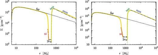
Comparison of the numerical solution (thick yellow solid lines) with the asymptotic analytical approximations in the various zones (dotted, dashed and dash–dotted lines, labelled as in Table 2) for the surface density of the disc around a 105 M⊙ primary. The mass ratio and binary separation are (q, rs) = (0.01, 500 M) and (0.1, 1000 M) on the left- and right-hand panels, respectively. In both cases the disc is in the overflowing steady state. The tidal torque is unsaturated in the near zone outside the Hill radius on the left-hand panel, but it is saturated on the right-hand panel. The disc structure is significantly modified in both cases in an extended region around the secondary.
5.2 Brightening factor
As stated in the previous sections, the ks parameter sets the angular momentum flux and the brightness of the disc in the middle zone relative to the unperturbed value, and determines the state of the disc.
Remarkably, the disc parameters can differ dramatically from the unperturbed values not only in the near zone, where the tidal effects dominate, but also in the middle zone, where tidal effects are already negligible. The tidal effects of the secondary are short range, but the corresponding effect is communicated to distant regions by setting an effective boundary condition. The size of this region can be  times larger than the secondary orbital radius (see Table 3). This long-range behaviour is confirmed in our full numerical solutions and is also present in Lodato et al. (2009) and Chang et al. (2010) for a circumbinary disc with a cavity. The same ks parameter also sets the increase in the scaleheight, as well as the migration speed of the secondary. We have derived the analytical formulae for ks in the four relevant regimes summarized in the previous section. Due to its extended radial size, the integrated luminosity of the middle zone is often larger than that of the near zone in the torque-unsaturated case, overflowing state. However, the near zone may be brighter than the middle zone, when the system is in the torque-saturated, overflowing state (see Paper II for further discussions).
5.3 Migration rate
Finally, we have derived the migration speed of the secondary; approximate analytical formulae for our results are listed in Table 2. We find that in the regimes when a cavity forms, the migration in our solution is slower than the standard steady-state secondary-dominated Type II migration rate (Syer & Clarke 1995) by a factor λ11/16 ∼ 2. The Type II rate may be further reduced in non-steady state models if the accretion rate or the gas mass is limited (Ivanov et al. 1999; Lodato et al. 2009). However, in the new ‘Type 1.5’ regime we identify, with a partial pile-up and overflow, the migration is even slower.

In general, Type 1.5 migration is more rapid at larger rs, in contrast with the Type II rate, which is nearly constant, and the GW inspiral rate, which strongly decreases with rs. Therefore, as a real system evolves, it will first transition from an initial Type II migration at large radii to Type 1.5 migration at smaller radii, before finally being driven by GWs at still smaller separations.
Regarding the dependence on the primary mass, Type II is nearly constant, while the Type 1.5 speed increases with M•. This implies that at any fixed orbital separation, Type 1.5 migration is relevant for lower masses (roughly those in the range expected to be detectable by a space-based gravitational wave mission such as LISA, and Type II is relevant for higher-mass binaries (in the sensitivity range of Pulsar Timing Arrays; see Paper II). Type 1.5 migration may also be important for stellar mass binaries in proto-stellar discs or Jupiter-mass planets around M-type dwarf stars of mass (0.1–1) M⊙ (see Johnson et al. 2012, for a recent discovery of such a system). Finally, we note that Type 1.5 (Type II) migration operates for larger (smaller) accretion rates, if fixing all other parameters.
All of the above conclusions are based on the analytical solutions we obtained; however, we have verified, by numerically solving the equations presented in Section 2, that our solutions are accurate to within tens of per cent for a broad range of parameters. In particular, in Fig. 3 we show the analytical approximation of the migration rates for the case of rs = 1000 M• for M• = 105 M⊙, together with the rates obtained from a numerical solution. In this case, a disc is in the overflowing state for all values of q ≳ 10−3 shown, and the migration rate is significantly different from both Type I and II. As the figure shows, the analytical Type 1.5 formulae give a good approximation over a wide range of q for the migration speed.
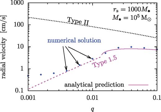
The migration speed of the secondary for different mass ratios for M• = 105 M⊙ at rs = 1000M• (or  ). The steady-state numerical solutions (blue) are well represented by our analytical formula for Type 1.5 migration (magenta), but not by those for Type I or II (black dotted). The dashed and solid magenta lines show the unsaturated and saturated Type 1.5 cases, respectively. The discrepancy between the numerical and analytical solutions becomes more significant at q < 0.002 due to the fact that the disc is not strongly perturbed there.
5.4 Caveats
Our findings are subject to many possible caveats.
- (i)
We assumed a radiatively efficient disc model in which the effective viscosity is proportional to the gas pressure in the disc with a constant α coefficient even in the radiation pressure-dominated regime. Future studies should investigate alternative models in which the viscosity is proportional to the total gas+radiation pressure (Shakura & Sunyaev 1973), or where the viscosity is generated by magneto-rotational instability (MRI; see Turner et al. 2003; Shi et al. 2012; Giacomazzo et al. 2012; Noble et al. 2012 for simulations of circumbinary discs leading to an ‘antigap’).
- (ii)
We assumed steady-state models where the accretion rate is constant over radius. This is expected to be valid as long as the gas inflow is much faster than the migration rate of the secondary over a large range of radii, if the total gas supply is not limited, and if the accretion rate is set at the inner or outer boundary (i.e. for the new Type 1.5 migration regime we focus on here). However, this assumption may be violated for tidally truncated circumbinary discs (Type II migration; Ivanov et al. 1999) or for models where the gas supply rate is limited at the outer boundary (Lodato et al. 2009; Rafikov 2012).
- (iii)
We assumed unequal-mass binaries, averaged over the azimuthal angle, assumed that the density waves generated by secondary are dissipated locally, and that the radial tidal torque profile follows the formula given by Armitage & Natarajan (2002). This assumes that the tidal torque saturates near the secondary at a radial distance closer than the scaleheight (
 ). We also assumed that the gas entering a distance comparable to the Hill radius can flow freely across the secondary's orbit. However, accretion on to the secondary may affect the Type 1.5 migration rate. Farther away from the secondary, the assumed torque density has a steep cutoff (
 ); extrapolating beyond r > 2rs might be inaccurate. The |r − rs|−4 scaling may also be inaccurate in the local non-linearly perturbed regime especially for comparable mass-ratio binaries (MacFadyen & Milosavljević 2008; Petrovich & Rafikov 2012; Roedig et al. 2012). These issues should be investigated using simulations, which could also address comparable mass binaries where the disc may be significantly non-axisymmetric (e.g. MacFadyen & Milosavljević 2008; Cuadra et al. 2009) and where the accretion of the secondary is non-negligible (Lubow et al. 1999).
 - (iv)
We neglected non-axisymmetric inflow into the secondary's orbit or on to the secondary if a cavity is formed. Inflow across the gap or accretion of the secondary reduces the amount of pile up outside the secondary, reduces the Type II migration rate and could affect the gap closing transition between the continuously overflowing solutions and the cases with a gap. We have also neglected the corotation torques in the overflowing case.
- (v)
We found that the enhanced pressure dominates over the increase in surface density outside the secondary's orbit, which makes the overflowing disc stable against gravitational fragmentation (see Paper II). However, the steep pressure gradient in the near zone around a massive secondary may lead to global non-axisymmetric dynamical instabilities (Papaloizou & Pringle 1985; Goldreich, Goodman & Narayan 1986). The corresponding enhancement of the effective viscosity and angular momentum transport in the disc might reduce the pile-up outside the secondary's orbit and further reduce the Type 1.5 migration rate. A detailed stability analysis and an investigation of its implications go beyond the scope of this paper.
- (vi)
We restricted our attention to circular binaries. However, binary eccentricity may be excited in cases with a cavity, when the masses of the two compact objects are comparable and the gap edge itself becomes significantly non-axisymmetric (Artymowicz 1992; Armitage & Natarajan 2005; Roedig et al. 2011, 2012). We note that such non-axisymmetries excited in discs with a gap diminish once the mass ratio is q ≲ 0.1 (D'Orazio, Haiman & MacFadyen 2012). Nevertheless, it remains to be seen if the binary develops significant eccentricities in the unequal-mass, overflowing state, with a significant pile-up.
- (viii)
We assumed that the binary is sufficiently widely separated that gravitational wave emission is negligible. For a complete picture, future studies should investigate the gravitational wave driven regime (Chang et al. 2010; Tanaka & Menou 2010; Farris, Liu & Shapiro 2011; Kocsis et al. 2011; Yunes et al. 2011; Bode et al. 2012; Baruteau et al. 2012; Giacomazzo et al. 2012; Noble et al. 2012; Tanaka, Menou & Haiman 2012).
6 Conclusions
In summary, we have presented new analytical solutions to disc properties and migration rates, obtained from self-consistent solutions of a coupled binary--disc system. The evolution equations are solved analytically in the strongly perturbed limit, including the angular momentum exchange between the disc and the binary and the modifications to the density, scaleheight and viscosity self-consistently, including viscous and tidal heating, diffusion limited cooling, radiation pressure and the orbital decay of the binary.
In addition to recovering solutions with a central cavity, similar to previous ‘Type II migration’ scenarios, we have identified a distinct new regime, applicable at smaller separations and masses, larger accretion rates and mass ratios in the range 10−3 ≲ q ≲ 0.1. For these systems, gas piles up outside the binary's orbit, but rather than creating a cavity, it continuously overflows as in a porous dam. The disc properties are intermediate between those in an unperturbed disc and a disc with a wide gap. The migration rate of the secondary in this ‘Type 1.5’ regime is typically slower than both Type I and Type II rates.
In this paper, we have presented simple analytical formulae that comprehensively describe binary systems with different parameters in various stages of evolution. The analytical results provide simple scaling relations, which may be useful to scale and interpret the results of numerical simulations to different disc or binary parameters. It allows us to map out the effects of varying α,  , or the binary parameters, over a wide range from planetary discs to active galactic nuclei around SMBH binaries.
We discuss the applicability of the new Type 1.5 regime and its physical implications for specific systems, as well as possible observable signatures in a companion paper (Paper II).
Acknowledgments
We thank Re'em Sari, Taka Tanaka, Alberto Sesana and Roman Rafikov for useful discussions. BK acknowledges support from NASA through Einstein Postdoctoral Fellowship Award Number PF9-00063 issued by the Chandra X-ray Observatory Center, which is operated by the Smithsonian Astrophysical Observatory for and on behalf of the National Aeronautics Space Administration under contract NAS8-03060. This work was supported in part by NSF grant AST-0907890 and NASA grants NNX08AL43G and NNA09DB30A (to AL) and NASA grant NNX11AE05G (to ZH).
References
Appendix A: Viscously and Tidally Heated Discs
Here we provide the details of the algebraic manipulations that give the disc model for fixed F and Dν for either α or β-discs (i.e. b = 0 or 1).
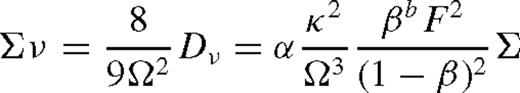
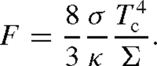
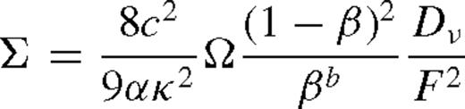
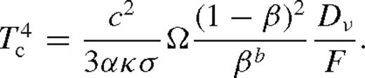
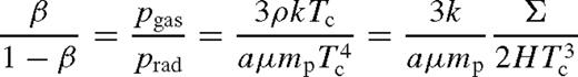
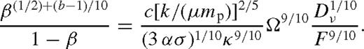
Finally equations (154) and (155) can be simplified by eliminating 1 − β using equation (157), which leads to (21)–equations (22).
Here ν ∝ pgas and ν ∝ (pgas + prad) are, respectively, known as α- and β-models. We formulate our problem for a general α- or β-disc in Section 2, but then derive the analytical results for the special case of a β-disc viscosity.
 and
and  . T refers to torque, Tν and Td are viscous and tidal torques as in Chang et al. (
Liu & Shapiro (2010) used equation (5) with f = 10−2. Chang et al. (2010) adopted a torque model, extrapolating equation (18) of Goldreich & Tremaine (1980) (with a modified constant prefactor of  ), such that their torque density approaches a constant at r ≫ rs. The linear perturbative analysis of Goldreich & Tremaine (1980) is not applicable if q ≳ α2 or q ≳ (H/r)3 (Meyer-Vernet & Sicardy 1987; Ward 1997; Korycansky & Papaloizou 1996).
Recent simulations (Dong et al. 2011a; Rafikov & Petrovich 2012; Duffell & MacFadyen 2012) have shown that the original Goldreich & Tremaine (1980) torque density is correct close to the secondary, but the actual torque decreases in amplitude and changes sign outside of rs + 3H. However, the relative contribution of these outer regions to the total torque is negligible.
As stated above, we neglect the accretion on to the secondary for simplicity (however, see Lubow, Seibert & Artymowicz 1999).
Note that the gas is not degenerate and is not isentropic, therefore the assumption of p ∝ ρ5/3 or ρ4/3 made in most numerical simulations of accretion discs is inappropriate. In fact,  for a radiation-pressure dominated standard Shakura–Sunyaev disc with no secondary.
One possible source of inconsistency is that convective vertical heat transport is conventionally neglected here. This may be significant for optically very thick, radiation pressure-dominated discs (especially the so-called β discs) with a large vertical temperature gradient (Blaes et al. 2011). The heat transport in this regime may be analogous to the convection zones of stars.
We add a factor of 2 that appears to be missing in Lodato et al. (2009); this enters because of the two disc faces.
We find a small difference in the density and temperature normalization constants, due to Goodman (2003) neglecting a 4/3 prefactor in the vertical diffusion equation  .
.
The model is furthermore self-consistent only outside the secondary's Hill sphere since the gravity of the secondary is accounted for as a perturbation to the primary's gravitational field, and the equations are linearized in the derivation of the torque formula. The tidal torque model is nevertheless often interpolated to within this region as well (e.g. Goldreich & Tremaine 1980; Armitage & Natarajan 2002). Here we avoid this extrapolation by excising the region within the Hill radius from our domain, assuming that gas entering this region flows across the secondary orbit.
The tidal torque is monotonically increasing interior to the secondary's orbit and it is decreasing exterior to it. The solution is uniquely determined by the initial value Tν(rISCO) and Tν(ri) in the two domains. However, ri can be arbitrary as long as r0 > rs.
In practice, we generate solutions for many different ri. We seek the radius rg at which the tidal torque cuts off in the numerical solution: Td(rg) = 0.1 Td(rpeak) where rg > rpeak and rpeak is where Td(r) attains its maximum. We use this value as the gas velocity vr(rg) in equation (37). We find that the gas velocity is nearly constant in the neighbourhood of rg and the surface density is near its peak, so the solution is insensitive to the details of this convention.
Here  using the Syer–Clarke parameter
  .
.
This is different from a transient truncated circumbinary disc where the migration velocity is comparable to the local gas accretion velocity, which can exhibit hysteresis throughout the middle zone (Rafikov 2012).
Note that matching the derivatives at the interface does not contradict  there.
The disc rotates with nearly the local Keplerian angular velocity, but slightly slower due to a radial pressure gradient: (ΩK − Ω)/ΩK ∝ H2/r2 9see equation (78) in Kocsis et al. (2011)].
Note that in this section we use δr ≡ r − rs instead of Δ since in this region Δ = max (δr, H) = H (see equation (6)).
The Lambert W-function is defined to be the inverse of the function  , where we need the real branch with the larger absolute value,
  , defined on f > −e−1 = −0.368. The approximation in equation (111) is correct to within 20 per cent for all 0 < a < 1/e.
Recall that Tbc = Tν at the interface between the near and middle zone.
We have further restricted the near zones to lie outside the Hill radius of the secondary.
If either  ,
,  ,
,  or
or  is less than one, then the disc does not have a middle zone by definition, and the disc is not strongly perturbed.
Here we assume that GW emission is negligible, and the disc drives the binary. See Paper II for further discussion.
Author notes
Einstein Fellow.
