


Abstract
Imaging of latex particles, especially those with low glass transition temperature (Tg) has been a challenging issue. Different sample preparation methods for characterization of the morphology of a poly(n-butyl acrylate)/polystyrene two-phase latex are discussed and compared in this study. A method via hydroxyethyl cellulose embedding combined with ruthenium tetraoxide (RuO4) staining for scanning transmission electron microscope (STEM) observation is developed. By using this method, the spherical shape of latex particles can be maintained without deformation. The degree of incorporation of RuO4 into latex particles and cellulose matrix is different, which makes latex particles readily identifiable from cellulose matrix under STEM. A series of latexes with different structures such as copolymer latex and organic-inorganic hybrid latex were also successfully investigated by this method. The results indicate this specimen preparation method can be applied to study the morphology of a wide range of latex systems.
Introduction
Synthetic latex is of great interest as these materials have very wide industrial applications such as coatings, paintings, and adhesives. With increasingly versatile synthetic routes, latex particles with a wide variety of morphological structures can be produced (Gaillard et al., 2007). The most commonly seen structures include core-shell, phase-separated, and latex-inorganic particle hybrids. The morphological study of structured latex is essential for a better understanding of their formation mechanism and thus, in turn, to guide the design of latex, optimization of synthesis strategy, and trouble shooting of failed batches.
Transmission electron microscopy (TEM) and scanning electron microscopy (SEM) are the most widely used techniques for latex imaging due to their broad range of magnification. However, challenges remain in the observation of latex particles by SEM or TEM. Both techniques require high vacuum operation. Liquid samples such as latex are completely dried under high vacuum condition. Without special pretreatment, latex particles with glass transition temperature (Tg) lower than room temperature deform and aggregate, and eventually form a film in the drying process. This makes the observation of individual latex particles very difficult, and like other polymers, latex particles are composed of elements with low atomic number, so their signal contrast with the electron microscope is low (Echlin, 2009). It is necessary to enhance the contrast of latex components chemically or physically for electron microscopy observation.
Currently, negative staining is one of the most commonly applied sample preparation techniques for latex particle observation. This technology was first developed for the observation of biological specimens and is seeing broader use for the characterization of polymer samples (Segall et al., 1995; Kirsch et al., 1999). In general terms, the principle of negative staining for TEM involves imaging of a thinly spread particulate material by surrounding it with a heavy metal–containing salt solution. Differential electron scattering by the heavy metal stain versus the lower atomic mass content of the material under investigation generates reverse-contrast negative electron optical images (Harris et al., 1999). Other sample preparation methods for latex morphology characterization include cryo-microtomy combined with RuO4 staining (Lee, 2006) and cryo fracture (Disanayaka et al., 1990).
The sample preparation techniques mentioned above have been intensively developed during the past decades. However, all exhibit certain limitations. For example, the preparation of negative stain solutions is complex (Harris & Horne, 1994). Uranyl acetate, a common ingredient in negative staining solutions, is radioactive and toxic. Microtomy preparation of frozen latex solutions combined with proper staining is helpful for study of the interior structure of latex, but the structure of latex particles can be broken during microtomy.
Development of cryogenic scanning electron microscopy (cryo-SEM) (Luo et al., 2007) and cryogenic transmission electron microscopy (cryo-TEM) (Crassous & Ballauff, 2006) techniques significantly simplified sample preparation of latex. The microstructure of latex is preserved through rapid freezing, and the particle aggregation phenomenon is minimized by observing the sample under a cryogenic environment, but the cost of the cryo unit is high.
Scanning transmission electron microscopy (STEM) in an SEM is a fairly recent technology (Guise et al., 2011). Compared with conventional TEM, the image contrast of STEM is considerably greater than in the TEM image. Because the operation energy of STEM is relatively low (15–30 kV), STEM is more suitable for characterizing beam-sensitive samples. By collecting electrons transmitted through the sample with a STEM detector, TEM-like images can be obtained on typical polymer morphologies such as a phase separated components of a polymer blend or crystalline lamellar structures within polymers. In the past few years, there are many examples of STEM imaging for characterizing polymer samples (Bogner et al., 2007; Garcia-Meitin et al., 2008; Barkay et al., 2009; Maraloiu et al., 2010).
In this communication, practical aspects of characterizing a poly(n-butyl acrylate)/polystyrene two-phase latex by STEM were explored. A fairly simple and fast method of cellulose embedding combined with RuO4 staining was developed. Representative latex samples composed of different monomers and with different structures were also studied by this method. By successful imaging of these samples, it is shown that this method is very effective in characterizing a wide range of latex samples.
Materials and Methods
Materials
In this study, a series of commercially available or research latex samples developed by the Dow Chemical Company (Midland, MI, USA) were investigated. A description of these latex samples is listed in Table 1. A series of colloidal materials including acrylic emulsion (AC261, Dow), hydroxyethyl cellulose (HEC) (QP 4400 H, Dow), polyethylene oxide (POLYOX WSR 301, AMERCHOL), and carboxymethyl cellulose sodium salt (CRT 100 PA, Dow) were applied as embedding media for the latex samples. Each specimen was stained in RuO4 vapor by placing the specimen above a 2% solution of RuO4 made by combining ruthenium (III) chloride hydrate (Sinopharm Chemical Reagent Co., Ltd., China) with 5.25% aqueous sodium hypochlorite (Sinopharm Chemical Reagent Co., Ltd.) (Blackson et al., 2007).
Materials Description.
| Designation | Description |
|---|---|
| C1 | Phase-separated PBA/PS latex |
| C2 | Poly(BA-co-MMA) latex |
| C3 | Blend of poly(BA-co-MMA) latex |
| C4 | Poly(BA-co-MMA)/nano silica composite latex |
| C5 | Poly(BA-co-MMA) latex with TiO2 encapsulated inside |
| Designation | Description |
|---|---|
| C1 | Phase-separated PBA/PS latex |
| C2 | Poly(BA-co-MMA) latex |
| C3 | Blend of poly(BA-co-MMA) latex |
| C4 | Poly(BA-co-MMA)/nano silica composite latex |
| C5 | Poly(BA-co-MMA) latex with TiO2 encapsulated inside |
Specimen Preparation
The samples are treated via different sample preparation methods as follows to image the latex particles.
- •
Method 1: One droplet of the original sample (35 μL) was placed on top of a pin holder and frozen in the FC 6 cryo-sectioning chamber of a Leica EM UC 6 microtome (Leica Microsystems, Wetzlar, Germany) at −100°C. Sections of 100 nm thickness were collected from the frozen sample at −100°C using a DiATOME Cryo 35° diamond knife (DiATOME, Hatfield, PA, USA) on the Leica EM UC 6 microtome and transferred to copper grids (400 mesh) inside the cryo chamber. The sections were stained with RuO4 for 15 min and then observed by STEM.
- •
Method 2: Two to three droplets (70–105 μL) of sample were dispersed in 50 mL of DI water. One droplet (35 μL) of the diluted sample was placed on a copper grid with a carbon film by a pipette, and excessive liquid was removed by filter paper. After drying at room temperature, specimens were stained with RuO4 for 15 min and observed by STEM.
- •
Method 3: Two to three droplets (70–105 μL) of sample were placed in 2 mL of AC 261. The mixture was dried into a film at room temperature. Sections of 100 nm thickness were collected from the dry film at −100°C using a DiATOME Cryo 35° diamond knife on a Leica EM UC 6 microtome. The sections were stained with RuO4 for 15 min and then observed by STEM.
- •
Method 4: Two to three droplets (70–105 μL) of sample were dispersed in either a 50 mL HEC water solution (0.6 wt%), a cellulose sodium salt (CMC) water solution (1 wt%), or a polyethylene oxide (PEO) water solution (1 wt%). One droplet (35 μL) of each above mixture was placed on a copper grid with a carbon film, and excessive liquid was removed by filter paper. After drying at room temperature, specimens were stained with RuO4 for 15 min and observed by STEM.
STEM Characterization
In this experiment, all STEM images were acquired on a FEI Nova NanoSEM 630 system (FEI Company, Hillsboro, OR, USA) equipped with a STEM detector. The optimum accelerating voltage was determined to be 15–20 kV, and the beam spot size was 3.5–5. The working distance was set at around 5–7 mm.
Atomic Force Microscopy Characterization
Atomic force microscopy (AFM) images were obtained on a Multimode III AFM (Bruker Nano Inc., Santa Barbara, CA, USA). The microscope was operated in the tapping mode, where the lever is oscillated at resonance and the feedback control adjusts for constant tapping amplitude. Scanning was carried out in air using commercially available silicon cantilevers and tips with nominal force constants of 48 N/m (LTESPW tapping mode). Estimated normal scanning forces under these conditions are in the 10−8 to 10−9 N range. The images were recorded using free amplitudes (A0) of A0 = 2 V and set-point amplitudes (Asp) of Asp = 1.4 V at moderate tapping in the overall repulsive interaction regime. The images were processed offline by applying a plane fit procedure to all images using the software IGOR Pro 6.04. Digital images are 512 × 512 pixels and pseudo-colored according to the measured property (height and phase).
Results and Discussion
Method Development
Multistage latexes that have more than one phase are widely used in industrial applications. This approach can give latex film properties that cannot be achieved by a physical blend of two or more different latexes. In this work, a poly (n-butyl acrylate)/polystyrene two-stage latex was chosen for the detailed study of various sample preparation techniques on the microscopic analysis of latex particles. The two-stage latex has a structure illustrated in Figure 1. Polystyrene domains (approximately 100 nm) were phase separated from poly (n-butyl acrylate) (PBA particles approximately 400 nm) and formed a salami-like morphology. The challenge to observe this type of structure is that PBA tends to form a cohesive film at room temperature, which makes the observation of individual particles very difficult.
Structure of phase-separated polystyrene/poly (n-butyl acrylate) latex.
If the sample was directly placed on a copper grid and naturally dried, the film formed would be too thick for STEM observation. To get specimens thin enough for STEM characterization, microtomy was used to prepare the sample. Sections of 100 nm thickness were collected from frozen sample and stained with RuO4 (method 1). Figure 2 shows STEM images of the sample prepared by this method. Black particles assigned to hard polystyrene (PS) domains can be observed distributed densely and evenly in the section. The contrast difference was due to selective incorporation of RuO4 to the PS hard domain, which resulted in stronger electron scattering, and hence a dark appearance of the particles in bright-field images. The PBA particles could not be observed through this method. The reason for this type of morphology was probably because the sections were collected from the original, nondiluted sample. The density of the PBA particles was very high. Coalescence occurred between PBA particles and a film of PBA was subsequently formed during the drying process at room temperature. The hard PS domains within PBA would then aggregate together and form this morphology, which appears as a high density of black particles. The two-stage latex particle with salami-like structure was not observed using this method. Also the PS particles observed were oval in shape. This might be caused by stretching during sectioning of the frozen sample.
STEM images of the two-stage latex collected from sections of frozen sample.
Results of the first trial indicate that to observe PBA particles the sample must be diluted to keep the particles from coalescing. Figure 3 shows STEM images of the water diluted sample, where the dilute solution was placed directly on a copper grid and subsequently stained with RuO4 following method 2 described in the Methods section. In contrast to the image acquired by cryo microtomy, bundles of PS aggregations were observed. Many PS bundles were encapsulated inside particles of around 800 nm (Fig. 3B). The outside particles should be PBA particles and the entire encapsulation structure should belong to a two-stage latex particle. Through this fairly simple approach, the structure of PBA/PS two-stage latex could be observed. The shape of the outside particle was not well defined, and the overall size is much larger than its exact size of 400 nm (particle size analysis). Meanwhile, structure of a lot of the two-stage latex seemed broken, and single PS particles could be found scattered on the carbon film. These observations indicate that appropriate water dilution can keep the particles from aggregating but cannot prevent them from deformation after being dried. The deformed two-stage structure could only be found in very rare places on the copper grid (Fig. 3A). This was probably due to the hydrophobicity of the carbon support film, so that most latex particles were unable to wet the carbon film when the sample was placed onto it.
STEM images of the two-stage latex dispersed in water by dripping the sample on the copper grid covered with a carbon film: (A) overview image and (B) high magnification image.
From the above it is clear that drying down from water will not be able to reproducibly fix the latex particle for imaging. To maintain the spherical shape of latex, a series of colloidal materials were used to disperse and hopefully play the role of fixing PBA particles. PRIMALTM AC 261 by Dow Chemical is pure acrylic latex with small particle size that can be applied to a broad spectrum of paint formulations, resulting in coatings with excellent long-term durability. With minimum film formation temperature around 16°C, AC 261 is able to form a continuous elastic film with low foaming. Since it is pure acrylic latex, a good dispersion of the two-stage latex in AC 261 is expected. However, the film formed on the copper grid was too thick for STEM observation by using AC 261 to disperse the sample. Sections of 100 nm thickness of the dry film were collected and observed with STEM as described in method 3. The PS bundles could be observed distributed evenly in the section (Fig. 4A). Compared with results obtained in the water dispersion method, the shape of PS bundles was rounder (Fig. 4B). Because the section thickness (100 nm) was thinner than the size of the two-stage latex (400 nm), most of the two-stage latex particles were cut during microtome. We observed sliced two-stage particles, so the size of most particles was smaller than their actual size. The contour of PBA particles was not observed by this method. This was probably due to PBA being composed of acrylic monomer, resulting in improved compatibility between PBA particles and acrylic emulsion particles. Coalescence occurred between PBA particles and acrylic emulsion particles, so their boundaries were not observable. However, it is possible to observe boundaries of the AC 261 matrix particles on close examination of Figure 4B.
STEM images of the sections collected from two-stage latex embedded inside AC 261: (A) overview image of 100 nm section and (B) high magnification image of 100 nm section.
To generate images with good particle shape as well as observable PBA contour, other colloidal materials such as PEO, CMC, and HEC were also applied to disperse the latex as described in method 4. Figure 5 shows STEM images of the two-stage latex dispersed in these materials. The distribution of latex particles in PEO was comparatively good, and the contour of latex particles was comparatively sharp in PEO. But PEO itself gives lamellar-like features after staining, which interferes with observation of the latex particles (Fig. 5A). Aggregation of latex particles in CMC was comparable to the acrylic emulsion, again lacking contrast for contour of the latex particles (Fig. 5B). The best image quality was obtained when HEC was used to disperse the sample (Fig. 5C). The contour of PBA particles in HEC was very sharp, and the contrast difference between PBA and PS was also strong, which made the two-phase structure of the PBA shell and PS domain very easy to observe. Structure of the two-stage latex was very well maintained through this method. Distribution of latex particles in HEC was good with no obvious coalescence occurring between the PBA particles. This method is comparatively simple and fast. If the HEC solution is ready, this method takes less than 2 h from sample preparation to morphology characterization.
STEM images of the two-stage latex embedded by different materials: (A) embedded by PEO, (B) embedded by CMC, and (C) embedded by HEC.
Application to Other Latex Systems
To demonstrate the success and broad applicability of the HEC embedding method for latex morphology, images from a range of latex particles with different structures are also presented in this article.
Butyl Acrylate–Methyl Methacrylate Copolymer Latex
Butyl acrylate (BA)–methyl methacrylate (MMA) copolymer latex is the most commonly used type of copolymer latex for architectural coatings. In the BA-MMA latex system, BA is a “soft” monomer while MMA is a “hard” monomer. By adjusting the ratio of BA and MMA, latexes from very rigid to very elastic can be obtained (Pei et al., 2004). Figure 6 shows the bright-field STEM images of BA-MMA latex with minimum film-forming temperature around 0°C by using HEC as the embedding material. It can be observed that the particles are well separated and easily identified. Since acrylic latex cannot pick up RuO4 stain, they appear as white particles in the images. Cellulose can be preferentially stained by RuO4, so it appears as a dark matrix in the STEM image surrounding the latex particles. The particle size of the latex is around 100 nm, which agrees with the particle size analysis results. This indicates that the particle structure of latex is preserved very well in HEC.
STEM images of a BA-MMA copolymer latex with particle size around 100 nm: (A) overview image and (B) high magnification image.
BA-MMA Copolymer Latex/Nano Silica Composite
The research of organic-inorganic hybrid nanocomposites has been an active area for a couple of decades (Luna-Xavier et al., 2002; Sherman & Ford, 2005). The supposed advantage of hybrid materials is that they combine the best properties of each component. They are widely used in plastics, rubbers, cosmetics, and coatings. Final performance of the hybrid material is often determined by the dispersion of inorganic particles in the polymer matrix. To get a good dispersion, the inorganic particles usually need to be functionalized or coated onto the polymer by means of electrostatic or chemical interaction. Morphology observation can provide direct evidence of functionalization condition of the inorganic particles on the polymer matrix. Figure 7 shows STEM images of a BA-MMA copolymer latex/nano silica composite. The small dots are nano silica and the big particles belong to BA-MMA copolymer latex. The nano silica particles are found distributed evenly on both latex particles and the medium around the particles. Although STEM does give high-resolution information for the sample, the result is a two-dimensional image projected from a three-dimensional structure. It is difficult to tell whether the silica particles are bound to the surface of the latex or buried inside the latex from STEM images. AFM can provide a surface image of a material with very high resolution. An AFM experiment was carried out to confirm the structure. HEC was applied to prevent the particle from coalescence. In contrast to the STEM sample preparation, the mixture of the sample and HEC was spin coated into a thin film on mica substrate for AFM observation with a KW-5 spin coating system (Institute of Microelectronics of Chinese Academy of Sciences, Beijing, China). Figure 8 shows the AFM height image and phase image of the latex composite. From the AFM phase image, we can clearly observe that nano silica deposits on the surface of the latex particle. Cellulose fixation combined with spin coating for AFM observation can be used for surface morphology characterization of latex, which is a good supplement to STEM observation.
STEM images of the BA-MMA copolymer latex/nano silica composite.
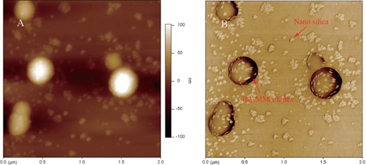
AFM height image and phase image of the BA-MMA copolymer latex/nano silica composite: (A) height image and (B) phase image.
TiO2 Particles Encapsulated by BA-MMA Copolymer Latex
Encapsulation of inorganic particles in a polymer shell has been a long-term objective in the coating industry because this strategy will help to prevent the agglomeration of inorganic particles and improve durability (Erdem et al., 2000). Emulsion polymerization is one of the most commonly applied techniques for encapsulation of inorganic particles. Morphology investigation is important for the study of polymer encapsulation systems because it can help verify whether the encapsulation is successful, determine the uniformity of the shell thickness, and help in understanding the encapsulation mechanism.
Figure 9 shows STEM images of TiO2 particles encapsulated with BA-MMA copolymer latex. The contours of latex particles are very sharp, and the contrast difference between TiO2 particles and polymer shell is obvious. It is easy to identify TiO2 particles and the latex shell from the images. All TiO2 particles are encapsulated inside the BA-MMA copolymer latex shell, and for most of the encapsulation, there is only one TiO2 particle within a BA-MMA copolymer latex, so the particles are very well separated without aggregation. The thickness of the shell is quite uniform, which demonstrates good control of the encapsulation process.
STEM images of TiO2 encapsulated by BA-MMA copolymer latex: (A) overview image and (B) high magnification image.
Summary
Morphology of the polyBA/PS two-stage polymer was observed with STEM. Different sample preparation methods were explored. RuO4 was applied to stain the sample. A series of colloidal materials including HEC, CMC, AC 261, and PEO were employed as embedding media for the latex particles. The results showed that by dispersing PBA/PS two-stage latex in HEC and staining with RuO4, the two-stage structure of PS domain encapsulated inside PBA particles could easily be observed. This is due to the differential incorporation of RuO4 into PS, PBA, and cellulose matrix. PS could be readily stained by RuO4, so that black particles are present in the image. Cellulose is amorphous and can be stained more than PBA particles by RuO4, so they appear as a gray matrix in the image. PBA is stained least by RuO4, so they appear as white particles in the image. Using HEC the spherical shape of PBA particles were very well maintained, which indicates the particles were well fixed by cellulose. This method was also applied to study a series type of latex with different structures including copolymer latex, latex-inorganic hybrid, and latex with inorganic particles encapsulated. Artifact-free images can be generated by this method demonstrating the broad applicability of this method for study of latex morphology. This morphology study can help researchers to observe the size, shape, and structure of the latex directly to better understand the efficacy of polymer synthesis schemes to produce desired properties. In addition, the preparation of the latexes for STEM imaging using HEC is rapid, taking less than 2 h.
Acknowledgments
We would like to thank Dow Coating Material business and Dow Advanced Functional Material business for the support of the project. We would also like to thank Georg Bar, Robert Cieslinski, John R Reffner, and Bob Vastenhout for valuable discussions.
