


Summary
The Taleghan fault (TF) is a major active fault of the Central Alborz mountain range in Iran. Located 50 km northwestwards of Tehran, this 80-km-long fault represents one of the major structures threatening 15 million people living in the capital of Iran and the surrounding cities (e.g. Karaj). The TF could be the source of some of the strongest historical earthquakes recorded in the Tehran region, notably the 958 AD event (estimated magnitude M 7.7). To characterize the kinematics and activity of the fault, we carried out a detailed morphological and palaeoseismological study combining aerial photographs, digital elevation models and fieldwork. We show that, unliked described so far, the TF is not a reverse fault but a left-lateral strike-slip fault with a normal component. Its strike, dip and rake within its eastern part are 105, 60 and –20/–40, respectively. Our palaeoseismological analysis shows that a sequence of 2–3 events with magnitudes Mw ≥ 7 occurred during the past 5300 years. If we consider a three-event scenario, the average recurrence interval is ∼2000 years, and the most recent event is younger than 80 AD. If we consider a two-event scenario, the time interval between the second and the first events ranges between 3760 and 830 years, and the elapsed time since the last event ranges between 3529 and 1599 years. Combined with morphotectonics data, our palaeoseismological analysis allows estimating a minimum horizontal slip rate of 0.6–1.6 mm yr−1 and a minimum vertical slip rate of ∼0.5 mm yr−1. Taking the ∼450-m total vertical displacement observed across the fault, we conclude that the kinematical change along the TF (from reverse to left-lateral + normal) occurred ∼1 Ma.
1 Introduction And Tectonic Setting
The Taleghan Fault (TF) is located near the southernmost border of Central Alborz, 50 km northwestwards of Tehran, the capital of Iran (Fig. 1). This 80-km-long EW trending fault extends from 50°30′E longitude (where it connects the southern Central Alborz piedmont) to 51°15′E longitude (where is connects the Karaj valley). With other nearby active faults such as the North Tehran fault (Nazari 2006; Ritz et al. 2008) or the Mosha fault (Ritz et al. 2003, 2006), the TF fault represents an important seismic hazard for the Tehran metropolis and its western suburbs (i.e. Karaj city), where more than 15 million people live. It might have been the source of one of the strongest historical earthquake in Alborz: the 958 AD earthquake of modified Mercalli intensity (MMI) = X (estimated equivalent surface wave magnitude Ms = 7.7) that devastated the region of Taleghan–Rey (Taleghan is a city in the valley northwards of the TF fault; Rey was a city located in the region where is now the southern suburbs of Tehran metropolis) and was felt as far as Baghdad (Ambraseys & Melville 1982; Berberian et al. 1993; Berberian & Yeats 1999, 2001) (Fig. 1). During history, the city of Rey has been destroyed by several other earthquakes (with estimated magnitude M > 6.5) in 312–280 BC, 743 AD, 855 AD, 856 AD, 1177 AD and 1830 AD (Fig. 1) (Ambraseys & Melville 1982; Berberian & Yeats 1999, 2001), and some of them might also be associated to the TF.
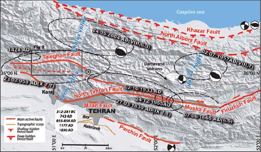
Seismotectonic sketch map of Central Alborz: Black dashed circles represent the epicentral areas and dates of historical earthquakes; dates inside the white diamond correspond to historical earthquakes that damaged the Tehran/Rey area (after Berberian et al. 1993; Berberian & Yeats 1999, 2001). Focal mechanisms of instrumental earthquakes after McKenzie et al. (1972); Jackson et al. (2002); Tatar et al. (2007). The asterisk indicates the location for Fig. 5. The grey area, mapped from Google Earth, corresponds to the urban area of Tehran and Karaj.
In the geological maps at 1:100 000 and 1:250 000 scales (Annells et al. 1977, 1985; Vahdati-Daneshmand et al. 1991, 2001), at large scale, the TF fault appears as a south-dipping thrust, with Precambrian and Jurassic deposits overthrusting lower Cenozoic formations (Karaj Formation). The fault is also described as a south-dipping thrust at present (e.g. Berberian & Yeats 1999, 2001; Allen et al. 2003; Guest et al. 2006).
However, a recent morphotectonics study showed that when observed at a smaller and more recent timescale, the TF fault has a left-lateral strike-slip movement associated with a normal component (Ritz et al. 2006). Together with the nearby Mosha fault, the TF fault defines a transtensional wrenching zone inside Central Alborz. This pattern is interpreted by Ritz et al. (2006) to be associated with the recent partitioning (see Jakson et al. 2002; Allen et al. 2003) between thrusting deformations within the external borders of Central Alborz and left-lateral strike-slip deformations inside the range. According to the orientation of pre-existing structures, the strike-slip motion can be associated with a normal component (Ritz et al. 2006). An interesting feature of the TF fault, as with the eastern Mosha fault, is therefore to have changed their kinematics very recently. This change is so recent that the previous relief, created during the compression, has not been reversed yet. This reversal is well visible, at smaller scale, within the northern flank of the massif bounding the Taleghan valley, where a wide topographic scarp (clearly identifiable even in Google Earth) forms a counter-slope (Fig. 2). To go further in characterizing precisely the geometry and kinematics of the fault, as well as its recent seismic activity (i.e. ages and magnitudes of the past earthquakes that occurred during the Holocene), we carried out a detailed morphotectonics and palaeoseismological study of the TF fault.
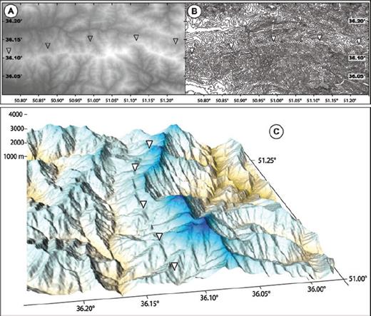
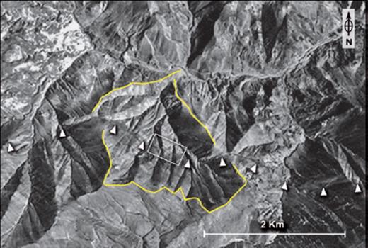
The Taleghan fault in the morphology (triangles point out the counter-slope scarp observed all along the fault). (a) Shaded topographic map. (b) Topographic map with 100-m contour levels. (c) 3-D view of a digital elevation model of the eastern part of the Taleghan fault (from the digitized topographic map of Asara 1:50 000).
2 Morphotectonics
Our analysis in morphotectonics is based on air photographs, digital elevation models (DEM) and field observations. Fig. 3 shows a map of the morphological features, interpreted as fault scarps, which are observed along the TF fault from air photographs analysis. Fig. 4 shows a few examples of these fault scarps observed in the field. At all scales of observation, the fault is characterized by a wide topographic scarp whose counter-slope morphology indicates a left-lateral normal motion along a main south-dipping plane.
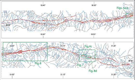
(a) Map of the morphotectonics features observed along the Taleghan fault from stereoanalysis of air photos: black lines (crest lines), blue lines (drainage) and red lines (fault scarps). Rectangles enclose areas shown in the following figures.
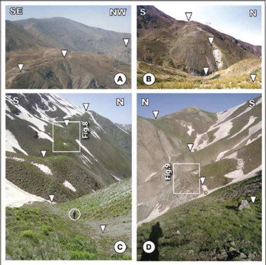
Field pictures of the fault scarps along the Taleghan fault (see Fig. 3 for location). Triangles indicate the main fault rupture. Panels (a) and (b) show the fault zone within its central part. Panels (c) and (d) show the fault within its eastern part. Note the southern dip of the main rupture (people circled for scaling the pictures).
Within its western and central parts, the fault scarp zone reactivates an EW to ENE–WSW trending old thrusting shear zone between the Palaeozoic and Precambrian formations (hangingwall, south) over Cenozoic deposits (footwall, north). In some places, one observes several lines of surface ruptures defining a wide topographic bench with an almost flat slope (Figs 4a and b). Within its eastern part (east of 51.10°, see Fig. 3), the rupture zone is less complex with a single main rupture line trending WNW–ESE (with few associated secondary surface ruptures), reactivating a thrust contact of Cretaceous–Jurassic deposits (hangingwall, south) overlying the Neogene Karaj Formation (footwall, north) (Figs 4c and d).
The main rupture appears steeper within the western and central zones (where it bounds to the north of the rupture zone, see Fig. 4b) than within the eastern part, where its more sinuous trace in the morphology defines a 60° dipping plane (Fig. 4c). The TF fault extends to the east as far as the valley of Karaj, where it is underlined by a brown gouge zone cutting through the bedrock (Fig. 5). Slickensides along a fault plane (small-scale feature) within the gouge zone indicate a strike, dip and rake of 120, 30 and –30, respectively. This characterizes a left-lateral strike-slip movement with a normal component.
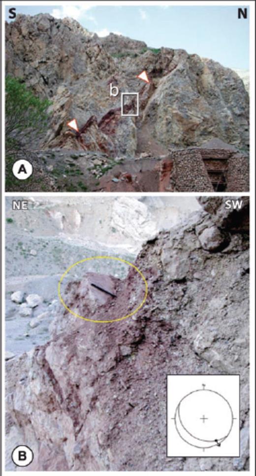
(a) Picture taken on the right side of the Chalus–Karaj road following the valley of Karaj River showing the Taleghan fault (brown gouge zone) cutting through the bedrock (see asterisk in Fig. 1 for location). (b) Close-up of fault slip data observed within the gouge zone showing slickesides, and plot of the fault plane and the slip vector on a Wullf stereoplot (lower hemisphere).
2.1 Kinematics of the Taleghan fault
Using the digital topography at large scale, we made a first, preliminary reconstruction of the kinematics of the TF fault. We focused our analysis on two shifted crest lines in the central part of the fault (Fig. 6). A first crest line is offset horizontally of 250 ± 50 m (A′B′ in Fig. 6a) and vertically of 80 ± 40 m (A′B′ in Fig. 6b2). A second crest line is offset horizontally of 150 ± 50 m (C′D′ in Fig. 6a) and vertically of 70 ± 20 m (C′D′ in Fig. 6b1). Using the trigonometric functions Vf = V/sin δ and ρ = artg(Vf/H), where H is the horizontal component, V the vertical component, Vf the vertical component projected along the fault, δ the dip and ρ the rake (see Fig. 6c), we estimated a rake for the slip vector comprised between –20 and –30.

(a) Digital topographic map (UTM coordinates) showing left-lateral offset features (drainage and crest lines) within the central part of the Taleghan fault (see Fig. 3 for location). Black lines (crest lines) and orange and green lines (offset axes of crest lines within the fault). (b1, b2) Vertical profiles along the offset crests axes with estimates of the cumulated vertical component. Minimum values correspond to the difference in height between the highest points in the green footwall profiles and the lowest points in the orange hangingwall profiles. Maximum values correspond to the vertical separations between the projections of the footwall and hangingwall profiles on a 60° south-dipping fault plane (this dip value is constrained by field observations). (c) Diagram defining the parameters for the calculation of the rake (ρ) of the slip vector (SV): H, horizontal component; V, vertical component; Vf, vertical component projected along the fault; δ, dip of the fault plane.
We constrained better the kinematics of the fault at a smaller scale within its eastern part, where a small catchment basin and its ridges and talwegs are shifted left laterally along one single main rupture (Fig. 7). We carried out a topographical survey within two shutter ridges (see Figs 4c and d) by means of a kinematic Global Positioning System (GPS) station. Fig. 8 shows the results of our study within the ridge that is the most displaced. From the mapping of the rupture on the digital topography (the intersection of the fault with the topography defines a plane. From its gradient, the azimuth and dip are calculated), we determined a fault strike of 105° and a dip of 59° towards the south. The dip is very consistent with the value (60 ± 5°S) measured in trenches opened across the fault scarp west of the most displaced shutter ridge and within the second studied shutter ridge (see Fig. 8b for location of trenches). The horizontal shift of the ridge (H) is 14 ± 2 m (Fig. 8c) (a crude estimate of 16 ± 5 m is obtained within the talweg west of the ridge). The maximum and minimum values of the vertical component (V) are 9 m and 5 m, respectively, which yield an average value of 7 ± 2 m (Fig. 8d). Using H, V and the dip (δ), we estimated the rake (ρ) to be comprised between –20 and –40 (the average horizontal and vertical component—14 m and 7 m, respectively—yield a mean rake value of –30). We also made a second estimate of the rake of the fault in the eastern part of the surveyed area showing a smaller shutter ridge (Fig. 9). This estimate is rather crude, given the difficulty to define piercing lines. From the detailed digital elevation model, we estimated 7 ± 2 m of horizontal displacement (Fig. 9c) and 3 ± 2 m of vertical displacement (Fig. 9d). These values yield a rake comprised between –8 and –50 (the average horizontal and vertical component—7 m and 3 m, respectively—yield a mean rake value of –26).
Aerial photo of the active Taleghan fault in its eastern part showing the left-lateral normal displacement of a drainage basin (yellow line), its crests and talwegs (see Fig. 3 for location). White triangles indicate the fault line. The white rectangle indicates the area studied in details.
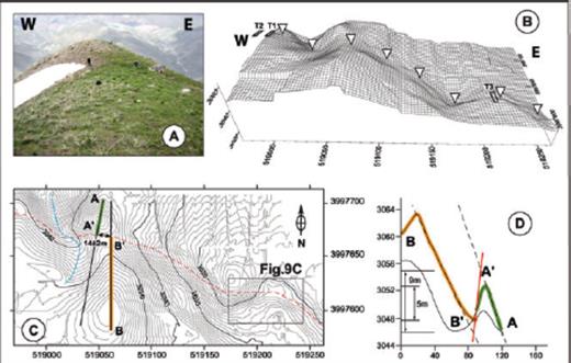
Result of the detailed topographic survey carried out within the offset drainage basin along the estern part of the Taleghan fault (see Fig. 7 for location). (a) Northward view of the main crest line shifted left laterally. (b) 3-D view of the digital elevation model obtained from GPS kinematics survey with locations of trenches (triangles indicate the fault line). (c) Topographic map showing the fault line (red dashed line) and the main shifted crest lines within the hangingwall (orange line) and the footwall (green line). (d) Vertical profiles along the offset crests axes with estimates of the cumulated vertical component. The minimum value corresponds to the difference in height between the highest points in the green footwall profiles and the lowest points in the orange hangingwall profiles. The maximum value corresponds to the vertical separations between the projections of the footwall and hangingwall profiles on the fault (considering a straight 60° dipping fault plane, erosion within the footwall scarp and ponding at the base of the hangingwall slope).
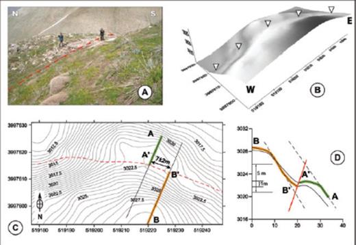
Details of the western part of topographic survey (see Fig. 8 for location, same captions).
3 Palaeoseismology
After having characterized the kinematics of the TF, we analysed its past seismic activity to provide an estimate of the recurrence intervals of earthquakes and their magnitude. Three trenches were hand-escavated at the site where we perfomed the morphotectonics study (see Fig. 8c for location). Two trenches located ∼15 m apart were dug within the narrow elongated sag depression westwards of the shutter ridge offset by 14 ± 2 m (Fig. 10a). A third trench was dug within the site described in Fig. 9, where the sag pond is smaller.
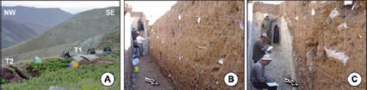
(a) Field picture showing the trenches T1 and T2 dug across the fault scarp, immediately west of the topographic survey shown in Fig. 8. (b) Northward view of trench T1. (c) Close-up of the fault zone within the eastern wall of the trench T1.
The three trenches cut through the fault and reached a depth of about 4 m (Fig. 10, 12–14). We logged the eastern walls (for reasons of light) of the three trenches, with a reference grid of 1-m square, at a 1/10 scale. In the three trenches, we observe a south-dipping fault separating sheared Cenozoic volcano-sedimentary rocks (Karaj Formation) in the footwall from colluviums deposits in the hangingwall.
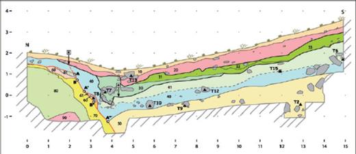
Log of the eastern wall of the trench T1 opened on the Taleghan fault. Unit 10: dark brown organic soil with roots, 40% clasts (5 mm–5 cm); unit 20: unstratified light brown colluviums with silty matrix, 30% clasts (5 mm–8 cm) with few big cobbles at the base; unit 30: unstratified light brown colluviums with silty matrix, 30% clasts (3 mm–5 cm), with big carbonate clasts (some >50 cm) at the base; unit 31: sorted, unstratified, light brown-to-beige colluviums with silty matrix, 20% clasts (3 mm–2 cm); unit 32: sorted, unstratified brown colluviums with silty matrix, 30% clasts (3 mm–2 cm); unit 33: well-sorted, unstratified, brown-to-dark brown colluviums with silty matrix, 10% clasts (3 mm–3 cm); unit 40: sorted, unstratified light brown colluviums with silty matrix, 10% clasts (5 mm–5 cm), a few big cobbles at the base; unit 41: sorted, unstratified, light brown colluviums with silty matrix, 20% clasts (3 mm–3 cm); unit 50: sorted, unstratified, brown-to-dark brown colluviums with silty-clayed matrix, 10% clasts (5 mm–15 cm), a few big cobbles (>25 cm); unit 60: yellowish brown layer of volcano-sedimentary rocks (Eocene bedrock, Karaj Formation); unit 61: beige-to-white layer of volcano-sedimentary rocks (Karaj Formation); unit 70: greenish-to-brownish gouge zone made of clayey material; unit 80: beige-to-white volcano-sedimentary rocks with alterations (Karaj Formation); unit 90: light grey volcano-sedimentary rocks (Karaj Formation); black thick lines and arrows with “e” indicate the event horizons (ground surface at the time of each event).
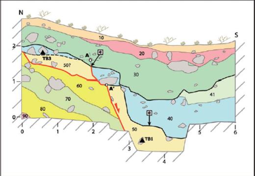
Log of the eastern wall of the trench T2 opened on the eastern part of the Taleghan fault. Unit 10: Dark brown modern organic soil; unit 20: unstratified, light brown-to-grey colluviums with silty-sandy matrix, 50% clasts (3 mm–5 cm), with big cobbles at the base; unit 30: sorted, unstratified light brown colluviums with silty-clayey matrix, 30% clasts (5 mm–7 cm), a few cobbles (>25 cm) at the base; unit 40: unstratified brown colluviums with silty matrix, 10% clasts (5 mm–7 cm), a few big cobbles (>25 cm) at the base; unit 41: unstratified, brown colluviums with silty matrix, 50% clasts (1 cm–4 cm); unit 50: unit mixing reddish brown silty muddy colluviums with green argillaceous rocks, 60% clasts (1 cm–7 cm), a few cobbles (>15 cm); unit 60: greenish-brownish gouge zone made of clayey material; unit 70: beige-to-white volcano-sedimentary rocks (Eocene Karaj Formation); unit 80: greenish-brownish gouge zone made of clayey material; unit 90: yellowish brown volcano-sedimentary rocks (Karaj Formation); black thick lines and arrows with “e” indicate the event horizons.
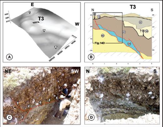
Palaeoseismological analysis of trench T3 on the eastern part of the Taleghan fault. (a) Location of the trench on the digital topography. (b) Log of the eastern wall of the trench. Unit 10: dark brown modern soil with roots, 50% clasts (10–100 cm); unit 20: brown-to-dark brown colluvium with clayed-silty matrix, 30% clasts (2–20 cm); unit 30: brown colluvium with clayed matrix, 60% clasts (5–50 cm); unit 40: brown-to-grey colluvium with silty-sandy matrix, 80% clast (10–100 cm); unit 50: light brown tectonic breccia made of Karaj material; unit 60: yellowish-to-greenish sheared volcano-sedimentary rocks from Karaj Formation; black thick lines and arrows with “e” indicate the event horizons. (c, d) Pictures of the eastern wall.
Within the colluviums, several units can be distinguished. The different units are unstratified, with cobbles generally found at the base, covered by a more or less sorted, fine pebbly material, included in silty or clayey matrix. Given the stratigraphy and structures in the trenches, it was difficult to recognize individual palaeoearthquakes. We could not distinguish the scarp-derived material (i.e. colluvial wedges, see, e.g. McCalpin 1996; Yeats et al. 1997) from the material derived from the southern topographic slope. Some units can be interpreted as a new influx of material, mixing colluviums derived both from the degradation of a fresh scarp (assumed to be associated to a coseismic slip along the fault) and from the steep southern slope. In this interpretation, this new influx begins with the rapid deposition of coarse material (occurring during or just after the earthquake) and is followed by the slow ponding of finer material. However, other units look simply being associated with climate changes and/or slope processes, notably those associated with the melt or the avalanche of the snow cover (the studied site is at ∼3000-m altitude and is covered with snow for a large part of the year) or possible landslides due to coseismic shaking produced by nearby faults.
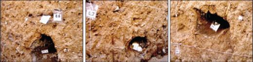
Within the cobbles, we observed an unusual feature: a thin dark brown layer of organic material is enclosing many of them, whereas no clear organic material or tracks of alteration is observed within the covering finer deposits—notably within their upper parts (Fig. 11). Our interpretation is that the cobbles rolled down into the sag pond, carrying with them pieces of the soil in which they were incased upslope (this interpretation is strengthened by the fact that we observed upslope the scarp dried soil material inside fissures of fractured blocks still embedded in the ground). In this hypothesis, the age of this organic material is older than the end of the soil formation and, therefore, predates each new influx of material that is trapped against the scarp. We used this interpretation to constrain the timing of the events.
Pictures showing examples of organic material found around cobbles (note that no organic material or tracks of alteration are observed within the finer deposits).
3.1 Trench T1
This trench is located ∼70–80 m westwards of the most displaced shutter ridge (see Fig. 8b for location). It exposes a set of colluviums in the hangingwall and the Cenozoic volcano-sedimentary rocks from the Karaj Formation in the footwall (Fig. 12). The rupture occurs along a 55° south-dipping gouge zone, ∼50-cm-thick (unit 70), splitting near the surface into two branches. A steep branch affects the colluviums (units 10–50) found above the 55° dipping fault, whereas a shallow branch flattens along the gouge zone towards the north. From the analysis of the trench wall, we interpreted two events.
3.1.1 First event
We interpret the colluvial unit 20, covering and eroding the underlying colluvial units, as the most recent event. In its northern part, unit 20 is dipping south and is derived from the scarp, covering unit 40 (which appears cut by the fault) and unit 30. In the southern part of the trench, unit 20 is dipping north and covers units 31, 32 and 33. This first event is younger than AD 80, which is the age found at the base of unit 30 (sample T7) below unit 20 (Fig. 12; Table 1). The age of unit 10 given by sample T13 collected around the large cobble is younger than 1660 AD (therefore, between the mid-1600 and the present); thus, we cannot constrain the upper limit for this first event.
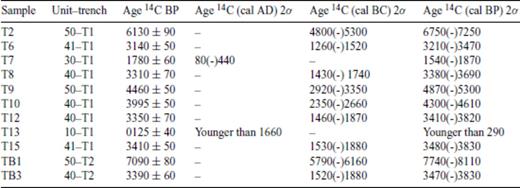
Calculated dates from 14C dating analysis of the organic material. Dendrochronologically calibrated calendar age ranges were calculated using the data set of Stuiver et al. (1998) with 2 standard deviation uncertainty. The age ranges are rounded off to the nearest decade.
Colluvial unit 20 could correspond to a deposit following one of the strong historical earthquakes (855 AD, 958 AD, 1177 AD, 1665 AD and 1830 AD) that occurred in the region (Ambraseys & Melville 1982; Berberian & Yeats 2001) and that could be associated to the TF fault or to the nearby Mosha or North Tehran faults. If the event occurred along the TF fault, it could coincide with the 958 AD earthquake, classically attributed to the Taleghan–Western Mosha faults system (see Fig. 1) or to the 1177 AD earthquake that affected the region between Qazvin and Rey (Qazvin is situated 100 km to the west of Karaj).
It is not possible to estimate straightforwardly the vertical displacement associated with this most recent event. A maximum estimate can be made by considering that the displacement of the bedrock units 60 and 61 along the fault (piercing points AA′, BB′ = 0.94, 1.34 m) is associated only to this youngest event. A minimum estimate can be made from the thickness of unit 20 (∼0.50 m), assuming that the unit results mainly from the destruction of a fault scarp, whose height was roughly equal to or larger than the thickness of the deposits (e.g. McCalpin 1996; Philip et al. 2001). This yields a vertical displacement (Vf) along the 55° dipping fault ranging between 0.6 and 1.34 m and a total offset ranging between 1 and 4 m, considering the –20/–40 rake estimated for the fault (see previous section).
3.1.2 Second event
We interpret the warping (drag) of units 40–41 along the fault as the evidence for a second event. This warping created a depression in which colluvial unit 30 deposited in a direction parallel to the fault, eroding underlying units 40–41. Taking the youngest radiocarbon age (sample T6) among samples in units 40–41 (samples T8, T10, T12, T15 and T6) and the age given by sample T7 in unit 30, this event occurred between 3470 and 1540 calibrated years BP (see Table 1). There is only one historical earthquake that can be associated to this event: the 312–280 BC earthquake of intensity MMI = X (equivalent estimated magnitude Ms = 7.6). This was classically attributed to the Parchin–Garmsar fault, ∼140 km to the southwest (Berberian & Yeats 1999, 2001); therefore, if it occurred along the TF, it was mislocated in the historical catalogue.
Although, we do not know what was the geometry of the base of unit 40 at the time of its deposition, an estimate of the maximum displacement associated with the second event is obtained by assuming that point A (top of the bedrock in the footwall) and point A′ (top of unit 50 in the hangingwall) were coincident before the event. Subtracting the displacement estimated for the first event (AA′, BB′ = 0.94, 1.34 m) from the distance A″ (2.8 m) yields a value of 1.46–1.86 m for the vertical displacement along the fault, and then taking into account the rake value, a maximum coseismic offset ranging between 2.26 and 5.10 m is obtained.
3.1.3 Other events
Considering the cumulated displacement observed within the morphology (the ridge situated immediately to the east of the trench is shifted horizontally of 14 ± 2 m; see Fig. 8), more than two events could be potentially recorded in the sag pond behind the scarp. It is possible that part of the unit defined as unit 50 corresponds to an event, but we could not distinguish whether the part against the fault corresponded to a faulted wedge.
3.2 Trench T2
The second trench T2 is situated ∼15 m west of T1 (Figs 10a and 13). As in T1, the footwall is made of sheared Cenozoic volcano-sedimentary rocks from the Karaj Formation (units 60–90) affected by a gouge zone (unit 60). A main 65° south-dipping plane is observed, separating the sheared bedrock units in the footwall from the colluvial deposits trapped within the hangingwall. The analysis of the trench wall allowed us to identify two events.
3.2.1 First event
We interpret the colluvial unit 30 (similar to unit 30 in the trench T1), covering and eroding unit 40 (similar to unit 40 in trench T1), as evidence for the most recent event. This event occurred after 3830 calibrated years BP, date of organic material (sample TB3) found around a cobble in unit 40, which is cut by the fault. An estimate of the amount of slip associated with this event can be made by proposing that point A′ (contact between units 40 and 50, along the fault, in the hangingwall) has been displaced ∼1 m from point A (intersection of two lines projecting the fault and the contact between units 40 and 50 in the footwall).
3.2.2 Second event
The second event is recognized by interpreting unit 40, covering and eroding unit 50 (similar to unit 50 in trench T1), as a post-event deposit, post-dating the wrapping (drag) of unit 50 along the fault. According to radiocarbon dating, this event occurred between 3470 and 8110 calibrated years (cal) BP, ages obtained for the organic material found beneath cobbles in units 40 (sample TB3) and 50 (sample TB1), respectively. It is not possible to quantify the displacement for this event.
3.3 Trench T3
The trench T3 is smaller than the other two and is located ∼300 m east of them, at a location where a shutter ridge is shifted horizontally (left-lateral) of 7 ± 2 m and vertically of 3 ± 2 m (normal) (Figs 8b, 9 and 14). T3 was opened after T1 and T2 were analysed to study the relationships between the offset topography and the sedimentary record within the sag pond (Fig. 14b). The trench shows a 55° dipping fault zone, with a section at 45° underlain by a tectonic breccia made of detrital material from the Karaj (Eocene) Formation. Near the surface, the fault rupture splits into two branches: a steep branch cuts through colluvial deposits (unit 40), whereas a shallow dipping branch extends further north. Note that within the steep branch, the brecciated Karaj material (unit 50) taken in the fault is found above the colluviums (unit 40), suggesting an apparent reverse movement. We interpret this geometry as the consequence of the lateral shift of contacts whose strikes are oblique to the rupture direction.
Within the hangingwall, the trench through the sag pond shows a ∼3-m-thick sequence of coarse colluviums, which is consistent with the vertical component (3 ± 2 m) estimated from the shutter ridge (see Fig. 9). We interpret the structures and stratigraphy exposed in this trench as the result of a maximum of two events: the first event is recognized by interpreting unit 10 as a post-event unit. We interpret a second event from the shape of unit 40 and its convex basal faulted contact along the bedrock, featuring a drag deformation similar to that proposed for units 40–41 in trench T1. Unit 30 can be interpreted as a post-event deposit, filling the depression subsequent to the deformation of unit 40. Both the lack of organic material and the coarseness of the colluvium precluded the possibility of constraining the ages of these events.
4 Seismic Behaviour of the Taleghan Fault
4.1 Moment magnitude Mw
From the vertical displacements measured along the fault (Vf, see Fig. 6c), we calculated the horizontal component using the rake value (−20/–40) determined from the morphotectonics analysis and then calculated the total offset (O) per event (Table 2). These offsets are comprised between ∼1 m and 5 m (with an average coseismic slip of ∼2.5 m). Assuming these offsets correspond to average displacements (AD), we estimated the corresponding moment magnitude Mw, using the Wells & Coppersmith (1994) empirical relationships for strike-slip faults (Mw = 7.04 + 0.89 logAD) (Table 2). After our displacement estimates, the magnitude maximum Mw expected for this fault ranges between 7.2 and 7.7. This is consistent with the magnitude estimated by Berberian & Yeats (1999) for the 958 AD historical earthquake (see Fig. 1) and suggests that strong earthquakes can rupture the entire 80-km-long TF (Wells & Coppersmith 1994 relationships yields a 7.3 magnitude for a surface rupture length of 80 km).
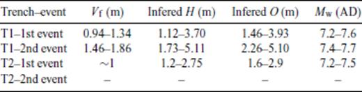
Table synthetizing the offsets parameters in metres and the corresponding moment magnitude Mw for the different events observed in trenches T1 and T2. Vf is the vertical offset measured along the fault (see Fig. 6C), H is the horizontal offset inferred from Vf and the rake value (–20/–40) and O is the total offset per event using the Pythagore theorem. Mw is the moment magnitude calculated from Wells & Coppersmith (1994) functions, considering O as an average displacement (AD).
4.2 Recurrence intervals of earthquakes
Our palaeoseismological data within trench T1 suggest that two events with magnitude Mw ≥ 7 occurred on the TF fault since 3470 calibrated years BP (youngest age obtained for units 40–41). The most recent event would be younger than 1870 calibrated years BP (AD 80). The second event occurred between 3470 and 1540 calibrated years BP. Our palaeoseismological data from trench T2 account for only one event since 3830 and a second event between 3470 and 8110 calibrated years BP.
The fact that we do not observe the youngest event in trench T2 is puzzling. Given the stratigraphy and structures in the trench, we cannot rule out the possibility that we have overinterpreted the features in trench T1. Indeed, we are not absolutely certain of the occurrence of a rupture cutting through unit 40 and sealed by unit 20 (the feature was logged as a dashed line in trench T1). Another possibility may be that this rupture is contemporaneous with the feature that we interpreted as a second event, that is, the warping (drag) of units 40–41 along the fault, followed by the normal deposition of unit 30.
However, this interpretation is difficult to admit when considering trench 3, where similar features (i.e. the split of the rupture into a steep branch and a shallow dipping branch) cannot be easily interpreted as a single event. There, the steep rupture cutting through unit 40 looks younger than the warping (drag) of the unit. Thus, another interpretation is that the youngest event in trench T2 is occurring along the shallow-dipping branch—as in the oldest event affecting unit 50—but cannot be seen, given the lack of northwards extension of the trench. This interpretation may explain why we do not measure the same total offset for unit 40 between trenches T1 and T2.
The correlation among trenches (T1 and T2) and ages (Fig. 15) allows tightening the time span during which the past 2–3 earthquakes occurred at 5300 calibrated years BP (the youngest age found in unit 50 from sample T9 in trench T1). The maximum recurrence time is 3760 years. If we consider a three-event scenario, the time intervals are 2295 ± 1465 years between the third and the second events and 1735 ± 1735 years between the second and the first events, yielding an average recurrence interval of ∼2000 years. If we consider a two-event scenario, the time interval between the second and the first events is 2295 ± 1465 years.
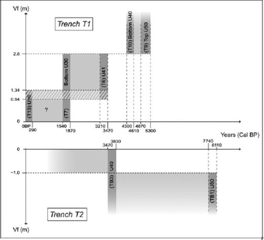
Sketch synthetizing the vertical offset projected along the fault offset Vf (see Fig. 6C) versus the time (calibrated years BP) of past events observed in trenches T1 and T2 (the third event in trench T1 is inferred from the correlation with trench T2). Bottom and top limits of oblique white dashed line bands define the minimum and maximum values of offsets. Dark grey bands correspond to the range of calibrated years BP bracketing the events (with indications of samples and units numbers). Light grey shaded areas describe our interpretations of the time windows during which the events occurred.
4.3 Elapsed time
If we consider a three-event scenario, the maximum elapsed time since the most recent event is 1929 years. The minimum elapsed time cannot be constrained by the radiocarbon age of post-event unit 10 in trench T1 (between the mid-1600 and the present). One hundred fifty years is a reasonable minimum bound, considering that if a magnitude M ≥ 7 earthquake had occurred along the TF since 1900 AD, it would have been recorded instrumentally. If we consider a two-event scenario, the elapsed time since the most recent event is ranging between 3529 and 1599 years.
4.4 Slip rates
We combined the results from the morphotectonics and palaeoseismological analyses to estimate horizontal and vertical slip rates along the TF fault. In trench T1, AA″ provides the separation (Vf = 2.8 m) along the fault since 5300 calibrated years BP (age of the top of unit 13 in trench T1). Taking an average fault dip of 60° and a fault rake comprised between –20 and –40, we estimate a minimum horizontal slip rate of 0.6–1.6 mm yr−1 and a minimum vertical slip rate of ∼0.5 mm yr−1.
4.5 Inception of the Taleghan fault activity
From the vertical slip rate, knowing the total vertical deformation and assuming that the slip rate is constant through the time, we can estimate when the left-lateral normal kinematics along the TF fault started. On the basis of several profiles across the digitized topographic map (see Fig. 2), we estimate a maximum value of ∼450 m for the total vertical displacement along the Taleghan cumulated fault scarp. Dividing this value by the ∼0.5 mm yr−1 vertical slip rate yields an age of ∼1 Ma for the beginning of the transtensional movement along the TF fault.
5 Conclusions And Discussion
Our detailed morphotectonics study along the TF allowed us to show that this active structure is a left-lateral strike-slip fault with a normal component (strike, dip and rake being 105, 60 and –20/–40, respectively). This transtensional deformation, reversing a previous thrusting deformation, is notably characterized by a counter-slope scarp observed all along the 80-km-long fault (see Fig. 2).
Our palaeoseismological analysis suggests that a sequence of 2–3 events with magnitudes Mw ≥ 7 occurred during the past 5300 years. The maximum recurrence time is 3760 years. If we consider a three-event scenario, we calculate an average recurrence interval of ∼2000 years. The most recent event is younger than 80 AD and could coincide with the 958 AD historical earthquake (estimated magnitude M = 7.7) classically attributed to the Taleghan–Western Mosha faults system (see Fig. 1). It could also be the 1177 AD earthquake (M = 7.2) that affected the region between Qazvin and Rey. If we consider a two-event scenario, the time interval between the two events is 2295 ± 1465 years, and the elapsed time since the last event ranges between 3529 years and 1599 years. Only one strong historical earthquake (312–280 BC) could coincide with this last event, but it is classically attributed to the Parchin–Garmsar fault ∼140 km to the southwest.
These results, as those obtained along the North Tehran fault (Nazari 2006; Ritz et al. 2008) or along the eastern Mosha fault (Ritz et al. 2003), show that it is difficult to determine the ages of palaeoearthquakes in this kind of arid and mountainous environment where the Holocene sedimentary record is coarse, irregular, intermittent in deposition and difficult to date. Our study also shows that attributing large historical earthquakes to a specific fault is difficult even in a country like Iran where there is an outstanding record of the historical seismicity.
From the morphological and palaeoseismological data, we estimated a minimum vertical and horizontal slip rate along the TF fault of ∼0.5 mm yr−1 and 0.6–1.6 mm yr−1, respectively. These rates are very consistent with those found along the eastern Mosha fault, also described as a left-lateral strike-slip fault with a normal component (Ritz et al. 2003, 2006). Similar to what is observed for the Mosha fault, the present transtension observed along the TF fault cannot be too old, considering that it did not cumulate enough deformation to reverse the previous relief (resulting from an earlier compressional deformation). After our estimates, the beginning of the transtensional movement along the TF fault would have started ∼1 Ma. This is consistent with the 1–1.5 Ma time period estimated for the beginning of the left-lateral normal motion along the Mosha fault (Ritz et al. 2006) and strengthens the idea that a regional kinematical change occurred recently within the South Caspian–Central Alborz region.
Acknowledgments
This study was carried out in the framework of a French–Iranian joint research project on the seismic hazard in Tehran region and was supported by the Geological Survey of Iran, the Centre National de la Recherche Scientifique (CNRS), the Agence National pour la Recherche (ANR) and the French Embassy in Iran. We are grateful to M.T. Korei, A. Saidi and D. Hatzfeld, coordinators of this projet. We thank M. Asad Beigi, A. Karbalai Hasan and S. Abedini for their help during trenching. We thank S. Solaymani for fruitfull discussions, A. Delplanque for drawings and F. Radjaie and G. Ganem for helping in editing the first and the final version of the manuscript, respectively. We also thank three anonymous referees for their thorough reviews that helped improving the manuscript. Radiocarbon analyses were performed in the framework of the LMC14 Artemis INSU programme.
References
