-
PDF
- Split View
-
Views
-
Cite
Cite
Simon J. Walsh, Ganesh Manoharan, Omar J. Escalona, Jose Santos, Noel Evans, John McC. Anderson, Mike Stevenson, J. Desmond Allen, A.A. Jennifer Adgey, Novel rectangular biphasic and monophasic waveforms delivered by a radiofrequency-powered defibrillator compared with conventional capacitor-based waveforms in transvenous cardioversion of atrial fibrillation, EP Europace, Volume 8, Issue 10, October 2006, Pages 873–880, https://doi.org/10.1093/europace/eul086
Close - Share Icon Share
Abstract
Aims To investigate the feasibility and efficacy of novel low-tilt biphasic waveforms in transvenous cardioversion of atrial fibrillation (AF), delivered by a radiofrequency-powered defibrillator.
Methods and results The investigation was performed in three phases in an animal model of AF: a feasibility and efficacy study (in 10 adult Large White Landrace swine), comparison with low-tilt monophasic and standard capacitor-based waveforms, and an assessment of sequential shocks delivered over several pathways (in 15 adult Suffolk sheep). Defibrillation electrodes were positioned transvenously under fluoroscopic control in the high lateral right atrium and distal coronary sinus. When multiple defibrillation pathways were tested, a third electrode was also attached to the lower interatrial septum. The electrodes were then connected to a radiofrequency (RF)-powered defibrillator or a standard defibrillator. After confirmation of successful induction of sustained AF, defibrillation was attempted. Percentage success was calculated from the effects of all shocks delivered to all the animals within each set of experiments. Of the low-tilt (RF) biphasic waveforms delivered during internal atrial cardioversion, 100% success was achieved with a 6/6 ms 100/−50 V waveform (1.45±0.01 J). This waveform was similar in efficacy to low-tilt (RF) monophasic waveforms (88 vs. 92% success, 1.58±0.01 vs. 2.67±0.03 J; P=NS; delivered energy 41% lower) and superior to equivalent voltage standard monophasic (50% success, 0.67±0.00 J; P<0.001) and biphasic waveforms (72% success, 0.69±0.00 J; P=0.03). Sequential shocks delivered over dual pathways did not improve the efficacy of low-tilt biphasic waveforms.
Conclusion A low-tilt biphasic waveform from a RF-powered defibrillator (6/6 ms 100/−50 V) is more efficacious than standard monophasic or biphasic waveforms (equivalent voltage) and is similar in efficacy to low-tilt monophasic waveforms.
Introduction
Atrial fibrillation (AF) is the most common sustained cardiac arrhythmia. Atrial fibrillation affects a broad range of patients and remains a challenging arrhythmia to manage in clinical practice. We previously reported that a novel passive implantable atrial defibrillator (PIAD) was a feasible method of internally cardioverting AF.1 This device uses an external radiofrequency (RF) energy transmitter to transfer energy to an internal defibrillator. Delivery of a low-tilt monophasic waveform by this method was shown to be highly efficacious for internal cardioversion of AF in the animal model.1 This novel waveform was also shown to be superior to tilted capacitor-based monophasic and biphasic waveforms.1,2
Several studies of epicardial and endocardial atrial defibrillation have demonstrated biphasic waveforms to be superior to their monophasic counterparts of equivalent overall duration. This has been shown in animal models3 of AF as well as in patients.4,5 We hypothesized that the PIAD efficacy could be improved by delivery of a low-tilt biphasic waveform. We explored methods of reducing the peak voltage of the defibrillation waveforms in order to make the method as clinically applicable as possible. Leading edge voltage is known to be an important determinant of pain during internal atrial defibrillation in patients,6–8 rather than total delivered energy.7 Delivery of sequential shocks over several pathways has been shown to reduce defibrillation thresholds previously9–12 and this method was also assessed.
The aims of this study are to investigate the feasibility and efficacy of delivering low-tilt biphasic waveforms for transvenous correction of AF, to compare the performance of these novel biphasic waveforms delivered from the RF defibrillator with a low-tilt monophasic waveform, conventional tilted (capacitor-based) monophasic and biphasic waveforms and assess whether delivery of sequential low-tilt biphasic shocks over several pathways would enhance the efficacy of atrial defibrillation.
Methods
All work was carried out in accordance with the United Kingdom Animals (Scientific Procedures) Act of 1986.
Equipment
Experiment 1
A custom-built rectangular waveform generator was developed. Novel rectangular biphasic waveforms (Figure 1, waveforms B and C) could be produced at a variety of phase-1 and phase-2 pulse durations. Both the phase-1 and phase-2 amplitude could also be adjusted, and the peak amplitude of the negative phase of the waveform was set as a percentage of the positive first phase. This equipment allowed a series of rectangular biphasic waveforms to be tested in an animal model of AF.
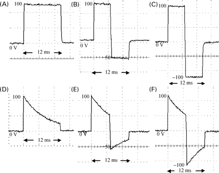
Waveforms tested during the investigation. Waveforms B and C are examples of those tested during experiment 1. The RF defibrillator generated waveforms A–C during experiment 2. Waveform A, rectangular monophasic waveform; waveform B, asymmetric rectangular biphasic waveform (phase-2 peak voltage reduced to 50% of phase-1); waveform C, symmetrical rectangular biphasic waveform (phase-2 peak voltage=phase-1). Waveforms D–F were generated by the Ventritex HVS-02. Waveform D, conventional monophasic waveform; waveform E, conventional asymmetric biphasic waveform (phase-2 peak voltage reduced to 50% of phase-1; equivalent time constant for both phases); waveform F, conventional symmetrical biphasic waveform (phase-2 peak voltage=phase-1).
Experiment 2
An RF power source was developed for the rectangular waveform generator. This unique device used two coils to transmit and receive RF energy via an inductive link. Rectified power levels of 200 W were transferred through an air gap (to simulate transcutaneous energy transfer; Figure 2) between the primary and the secondary coils. The primary coil (radiofrequency transmitter in Figure 2) represents an external power source, and the secondary coil was designed as a passive stand-alone DC pulse generator. The DC produced by the secondary coil was subsequently converted to a monophasic or biphasic rectangular waveform by the rectangular waveform generator.
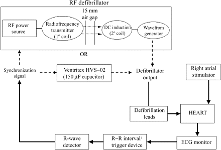
Schematic diagram of equipment layout for experiment 2. RF, radiofrequency; DC, direct current.
A Ventritex HVS-02 defibrillator (Ventritex, Sunnyvale, CA, USA) was used to deliver tilted, capacitor-based (150 µF) monophasic and biphasic waveforms. For the biphasic waveforms, both phase-1 and phase-2 were generated from a discrete 150 µF capacitor discharge. The performance of the tilted waveforms was compared with the rectangular waveforms delivered from the RF defibrillator.
Experiment 3
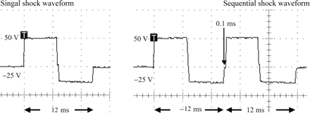
Modifications were required to enable the device to deliver two sequential shock waveforms across different pathways. The device was capable of delivering a single shock waveform or two sequential shock waveforms separated by 0.1 ms (Figure 3). The standard defibrillation pathway (right atrium to coronary sinus) could be used for delivery of a single or two sequential shock waveforms. When dual pathways were used, the atrial septum electrode was a common cathode and either anode (coronary sinus or right atrium) could be selected for the first or second shock. The initial 12 ms shock of the sequential waveform could be delivered across the left atrium or right atrium, and after 0.1 ms, the second 12 ms shock was delivered across the opposite pathway.
Procedure
In experiment 1, the rectangular waveform generator was assessed in a porcine model of AF (adult swine, n=10, mean weight 58±SD 2 kg, mean impedance between defibrillation electrodes 48±SD 5 Ω). Biphasic waveforms of differing pulse durations (3/3 and 6/6 ms) and phase-1 and phase-2 amplitudes (25–100 V) were assessed. In experiments 2 and 3 of the investigation, adult sheep were used as the experimental model of AF (experiment 2: n=10, mean weight 65±SD 12 kg, mean impedance between electrodes 48±SD 6 Ω; experiment 3: n=5, mean weight 64±SD 13 kg, varying impedances for each pathway). Both the porcine and sheep models of AF employed in this investigation have been previously described.1–3,9,13,14
The animals were anaesthetized with a 20–30 mg/kg bolus of intravenous pentobarbitone (Sagatal 60 mg/mL, Rhone Merieux Ltd, Harlow, UK), intubated and ventilated with room air (Model 16/24, Ideal Respirator, CF Palmer Ltd, London, UK). Anaesthesia was maintained with a continuous infusion of pentobarbitone (7–15 mg/kg/h titrated to maintain a steady plane of anaesthesia).
For experiments 1 and 2, defibrillation catheters were positioned in the high lateral right atrium (active fixation, Perimeter RA 7205, InControl Inc., Redmond, WA, USA) and the distal coronary sinus (Perimeter CS 7109, InControl Inc.) under fluoroscopic control (Figure 4). For experiment 3, a third defibrillation catheter (Perimeter RA 7205) was attached to the lower interatrial septum.
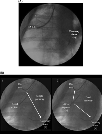
Fluoroscopic images of defibrillation leads. (A) Defibrillation leads for experiments 1 and 2. S, stimulator; RA, right atrium; (−), cathode; (+), anode. (B) Defibrillation leads for experiment 3. The standard single pathway is shown in panel 1, whereas the defibrillation electrodes used for dual pathway shocks are shown in panel 2. RA, right atrium; (−), cathode; (+), anode.
A single bolus of heparin (5000 U) was delivered at the beginning of the experiment. After the leads were positioned, the internal impedance between the leads was measured. The implanted electrodes were subsequently attached to the appropriate defibrillator during each experiment. AF was induced (100 Hz, 2 ms duration, 5 V stimulus) by burst pacing in the right atrium, via a bipolar catheter and a Grass stimulator (Grass S44 Stimulator). After confirmation of successful induction of AF, defibrillation was attempted.
The surface ECG, synchronization spikes (all shocks were R-wave synchronized) and arterial pressure tracings were displayed on a polygraph (Gould 2400 S). Body temperature and oxygen saturation were also monitored throughout the experiments. Temperature was maintained within normal limits by the use of a homeothermic blanket.
The voltage and current delivered during each shock were captured on an oscilloscope (Tektronix TDS 420A, four-channel digitizing oscilloscope, Tektronix Inc., Beaverton, OR, USA) and stored for analysis. The mean peak voltage, peak current, energy, and impedance were calculated from the stored data. The energy delivered was calculated by summing the areas under the instantaneous voltage–current product curves at 0.1 ms intervals. The ECG was assessed for evidence of pro-arrhythmia or atrioventricular block after defibrillation.
Protocols
Experiment 1
A total of 14 rectangular biphasic waveforms was randomly tested on each pig. The waveforms were assessed at two durations, 3/3 and 6/6 ms. At each duration, the waveform was assessed at four different phase-1 peak voltages (25, 50, 75, and 100 V). The phase-2, the voltage was set at either 100 or 50% of the first phase. The device could not generate waveforms at 25/−12.5 V, so these were not investigated.
Experiment 2
A total of 7 different waveforms was randomly assessed in each animal. All waveforms were 12 ms in duration, with biphasic waveforms delivered at 6 ms duration for each phase. Rectangular waveforms were delivered as monophasic or biphasic. The rectangular biphasic shocks were either symmetrical in amplitude or had the phase-2 peak voltage reduced to 50% of phase-1. Equivalent voltage capacitor discharges were delivered by the Ventritex HVS-02. However, the HVS-02 cannot deliver a 50/−25 V biphasic shock, as 50 V is the lowest voltage produced by this device.
For experiments 1 and 2, shocks were delivered between the right atrial (cathode) and distal coronary sinus electrodes (anode). Each waveform setting was evaluated five times in each animal, giving a total of 50 shocks per waveform. Percentage success was calculated from the effects of all 50 shocks in the 10 animals.
Experiment 3
Single pathway shocks (single or sequential waveforms) and dual pathway sequential shocks were assessed in random order. A single shock was 6/6 ms in duration, 50/−25 V in amplitude and rectangular. This voltage was chosen on the basis of the results from experiment 2. Approximately 70% success was anticipated and an increase in efficacy would be easier to demonstrate at this lower voltage level. Two identical sequential shock waveforms were delivered with a separation of 0.1 ms. A single shock was delivered between the standard right atrial to distal coronary sinus electrodes (as used in experiments 1 and 2). Sequential shocks were delivered over the standard single pathway or over 2 pathways. When dual pathways were used, the right atrial and distal coronary sinus electrodes were both anodes and the atrial septal electrode was a common cathode. The shocks could be delivered across the right atrium (septum to high lateral right atrium) or left atrium (septum to distal coronary sinus) in either order. Each waveform setting was evaluated 10 times in each animal, giving a total of 50 shocks per waveform. Percentage success was calculated from all 50 attempted defibrillation episodes in the five sheep.
Definitions
Sustained AF (>30 s in duration) was defined as a narrow QRS complex rhythm without P or flutter waves and with an irregular ventricular response. A return to sinus rhythm within five beats of shock delivery was deemed a successful cardioversion. Reversion to sinus rhythm beyond this interval was considered to be spontaneous and therefore a shock failure. Reversion to another arrhythmia was also deemed to be a shock failure.
Statistical analysis
All data are expressed as mean±standard deviation or standard error. The non-parametric Friedman test was used to evaluate differences between the success rates, mean energy, peak voltage, and peak current for the waveforms tested. Further assessment was made by means of logistic regression. All analyses were processed using the SPSS 12 for Windows software package (SPSS version 10, SPSS Inc., Chicago, IL, USA). Differences were considered significant at a value of P<0.05.
Results
A total of 1250 shocks (experiment 1: 700, experiment 2: 350, experiment 3: 200) were delivered, without induction of ventricular arrhythmias, precipitation of AV block, or haemodynamic compromise.
Experiment 1
All waveforms tested were rectangular biphasic waveforms, with phase-2 peak voltage equivalent to phase-1 peak voltage or reduced to 50% of phase-1 peak voltage (waveforms B and C, Figure 1). Success rates and delivered energy for each of the waveforms are presented in Figure 5. A dose–response was observed for waveforms of both 3/3 and 6/6 ms duration. The 6/6 ms 50/−25 V waveform was superior in efficacy compared with the equivalent voltage 3/3 ms waveform (92 vs. 58% success, P<0.001) and equivalent in performance compared with the 6/6 ms 50/−50 V waveform (92 vs. 80%, P=0.08). Similarly, the 6/6 ms 75/−37.5 V waveform was superior in efficacy compared with the equivalent voltage 3/3 ms waveform (98 vs. 84%, P=0.02) and equivalent in performance compared with the 6/6 ms 75/−75 V waveform (both 98%, P=1.0).
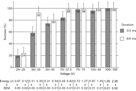
Cumulative success for waveforms tested in experiment 1. SEM, standard error of mean.
Multivariable analysis was also performed by binary logistic regression. Factors included in the analysis were delivered voltage, delivered current, delivered energy, waveform duration, and calculated impedance during the shock. This confirmed that the 6/6 ms duration shocks were more likely to correlate with a successful outcome (P<0.001) than those at the 3/3 ms duration. Phase-1 voltage correlated strongly with successful cardioversion (P<0.001), with each increase of 1 V raising the odds ratio for success by a factor of 1.08 (or 8%). The phase-2 voltage had much less impact on shock success. The correlation did not reach significance (P=0.081) and each increase of 1 V in the phase-2 value only increased the odds ratio for success by a factor of 1.02 (or 2%).
Experiment 2
Waveforms investigated are shown in Figure 1. Waveforms of 12 ms total duration were chosen for further investigation on the basis of the results of experiment 1. The rectangular RF monophasic (100 V), symmetrical biphasic (100/−100 V), and asymmetrical biphasic waveforms (100/−50 and 50/−25 V) all possessed <5% tilt. Capacitor-based waveforms included a monophasic discharge (100 V, 75% tilt), a symmetrical biphasic waveform (100/−100 V, 55%/55% tilt), and an asymmetrical biphasic waveform (100/−50 V, 55%/55% tilt). The results of experiment 2 are summarized in Figure 6.
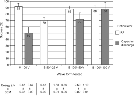
Cumulative success for 12 ms waveforms tested in experiment 2. SEM, standard error of mean; B, biphasic; M, monophasic.
Univariate analysis showed the RF 6/6 ms 100/−50 V rectangular waveform to be equivalent in efficacy to the RF 100 V monophasic and 100/−100 V rectangular waveforms. However, the 100/−50 V waveform delivered significantly less energy than both these waveforms (1.58±0.01 vs. 2.67±0.03 and 2.50±0.02 J, respectively, P<0.001). The RF 100/−50 V waveform was significantly more efficacious than the 100/−50 V capacitor discharge (P=0.03), although more energy was delivered (1.58±0.01 vs. 0.69±0.00 J, P<0.001). The RF 100/−50 V waveform was statistically equivalent in efficacy to the higher voltage capacitor-based 100/−100 V waveform (both 88% successful, P=1.0) and superior to the conventional tilted monophasic waveform of 12 ms duration (P<0.001): delivered energy was higher with the RF 100/−50 V waveform (1.58±0.01 vs. 1.10±0.01 J; P<0.001 and 1.58±0.01 vs. 0.67±0.00 J; P<0.001, respectively). In addition, the 50/−25 V RF waveform was equivalent in performance to the 100 V monophasic capacitor discharge (P=0.1) and 100/−50 V capacitor-based waveform (P=0.8), despite delivering significantly less energy than both of these waveforms (P<0.001 for both).
Experiment 3
Results obtained in experiment 3 are summarized in Table 1. The mean impedance across the standard right atrium to coronary sinus pathway was 51±SD 4 Ω, compared with 28±SD 6 Ω across the interatrial septum to right atrium and 55±SD 6 Ω across the interatrial septum to coronary sinus pathways. Therefore, the pathway across the right atrium was of low impedance.
| Shock type . | Pathway . | Electrodes . | Mean energy±SEM (J) . | % Success . |
|---|---|---|---|---|
| Single | Single | RA (−) to CS (+) | 0.37±0.00 | 70 |
| Two sequential | Single | RA (−) to CS (+) | 0.73±0.01 | 70 |
| Two sequential | Dual | First shock: IAS (−) to RA (+) Second shock: IAS (−) to CS (+) | 0.94±0.01 | 78 |
| Two sequential | Dual | First shock: IAS (−) to CS (+) Second shock: IAS (−) to RA (+) | 0.94±0.01 | 72 |
SEM, standard error of mean; CS, coronary sinus; RA, right atrium; IAS, interatrial septum; (−), cathode; (+), anode.
| Shock type . | Pathway . | Electrodes . | Mean energy±SEM (J) . | % Success . |
|---|---|---|---|---|
| Single | Single | RA (−) to CS (+) | 0.37±0.00 | 70 |
| Two sequential | Single | RA (−) to CS (+) | 0.73±0.01 | 70 |
| Two sequential | Dual | First shock: IAS (−) to RA (+) Second shock: IAS (−) to CS (+) | 0.94±0.01 | 78 |
| Two sequential | Dual | First shock: IAS (−) to CS (+) Second shock: IAS (−) to RA (+) | 0.94±0.01 | 72 |
SEM, standard error of mean; CS, coronary sinus; RA, right atrium; IAS, interatrial septum; (−), cathode; (+), anode.
There was no significant difference in the performance of the single shock across the standard pathway and any of the sequential shocks tested. Sequential shocks led to a significant increase in delivered energy compared with the single shock (all P<0.001). The greater energy delivery that was observed with the dual pathway shocks occurred due to higher current delivery across the low impedance pathway in the right atrium.
Discussion
Feasibility of the RF defibrillator and a novel biphasic waveform
The RF-powered defibrillator reliably produced biphasic and monophasic waveforms for internal atrial defibrillation. Experiment 1 demonstrated that transvenous atrial defibrillation can be achieved with rectangular biphasic waveforms at very low voltage and energy. One hundred per cent success was seen with energies as low as 1.45±0.01 J in this porcine model. The improved efficacy of the 6/6 ms waveform over the 3/3 ms waveform reflects a prolonged voltage exposure for the myocardium and enhanced chance of success. These observations are in keeping with previous investigators, who studied ventricular fibrillation and reported biphasic waveforms of ∼10 ms (6–16 ms total duration) as being highly efficacious.15–18 The results of Manoharan et al.1 in the animal model and Cooper et al.5 in patients also show optimal waveform duration of 10–12 ms for transvenous cardioversion of AF. This method is therefore, feasible, reliable, and highly efficacious at low voltage and energy.1,2
Waveform voltage, tilt, and energy
Radiofrequency monophasic and biphasic waveforms were highly effective in converting AF at low voltage and energy. Reduction of the phase-2 peak voltage to 50% of phase-1 did not reduce the efficacy of 6/6 ms rectangular biphasic waveforms for transvenous atrial defibrillation (similar performance of 6/6 ms 100/−100, and 100/−50 waveforms within experiments 1 and 2). These results are also in keeping with the findings of Schuder et al.,19 who examined rectangular biphasic waveforms in ventricular defibrillation in the calf. However, their results did show a reduction in waveform efficacy if these waveforms have phase-2 peak voltage reduced to less than 50% of phase-1.
Although the tilt of a capacitor-based waveform has previously been shown to be important in transvenous atrial defibrillation,7,20 in these experiments, rectangular monophasic and biphasic waveforms offer a significant improvement in efficacy compared with tilted capacitor-based waveforms at the same voltage setting (except the 100/−100 V biphasic capacitor-based waveform). Manoharan et al.1,2 also reported previously that a low-tilt monophasic waveform (100 V) was superior in efficacy compared with capacitor-based monophasic and biphasic waveforms (including a 100/−100 V waveform).
Irnich21 adapted the fundamental law of electrostimulation and applied this to ventricular defibrillation waveforms. When tilted waveforms are employed, if the concept of near-field and far-field rheobase (lowest current strength which successfully stimulates myocardium) is introduced, then attempted defibrillation with shock voltage below rheobase may be effective in stimulating myocardial cells close to the electrode (nearfield) but fail to affect cardiac tissue at a remote site (farfield).22 In theory, the reduction in voltage throughout the capacitor-based discharge is likely to decrease far-field voltage (in a sufficient percentage of the fibrillating myocardium) to a sub-therapeutic level, thus allowing fibrillation to continue. This may explain our superior results with rectangular waveforms.
Although these RF waveforms deliver more energy than their capacitor-based equivalents, leading edge voltage is a more important determinant of patient tolerability of internal atrial shocks.7 We have shown that removing the tilt from a waveform maximizes the efficacy obtained for a given voltage.
Monophasic versus biphasic waveforms
The majority of investigators have reported that capacitor-based biphasic waveforms offer superior efficacy compared with their monophasic counterparts (of similar overall duration) in terms of superior or equivalent efficacy at a lower peak voltage and delivered energy. This has been reported in animal models of internal atrial defibrillation3 as well as in patients.4,5 These results are also consistent for transthoracic cardioversion of AF23,24 as well as during many investigations of ventricular fibrillation.
Several theories have been suggested to explain why biphasic waveforms are superior to their monophasic counterparts. These include effects on ion channels with biphasic waveforms that do not occur with monophasic waveforms15 as well as more homogeneous dispersion of refractory period after biphasic pulses.25
We found a similar efficacy for a 100 V RF monophasic waveform compared with the 100/−50 V RF biphasic waveform. Although the production of the asymmetrical biphasic waveform facilitated a significant decrease in delivered energy compared with the 100 V monophasic waveform, there was no increase in efficacy. This result may be explained by the enhanced efficacy of the RF monophasic waveform and warrants further investigation.
Sequential shocks and the use of several pathways
Cooper et al.9,10 reported on the use of two sequential shocks delivered across ‘dual current pathways’. This method led to a reduction in atrial defibrillation threshold (ADFT) in sheep and patients.
Zheng et al.11,12 further reported on studies of dual current pathways with short duration (4 ms, capacitor-based) tilted biphasic waveforms in an animal model of AF. In their most recent investigation, using a purpose-built atrial/coronary sinus catheter, the dual current pathway associated with the lowest ADFT was the atrial septal electrode (cathode) to distal coronary sinus followed by the atrial septal electrode (cathode) to right atrial appendage.12 In keeping with our findings, a low impedance pathway was noted across the right atrium compared with the left atrial pathway.
Although we observed a non-significant increase in efficacy (from 70 to 78%) where two sequential shocks crossed the right atrium followed by the left atrium, our findings did not mirror those of Cooper or Zheng. This may be due to different defibrillation electrodes employed and the use of a novel asymmetric rectangular biphasic waveform rather than the conventional capacitor-based discharge.
There was also no increase in efficacy associated with delivering two sequential shock waveforms over the standard right atrium to distal coronary sinus (anode) pathway. This represents the delivery of a quadriphasic low voltage pulse over 24 ms, a manoeuvre that is unlikely to be successful as prolongation of discharges beyond 14 ms is known to have little additional benefit.18 Furthermore, given the disappointing effects of triphasic and quadriphasic waveforms, there is no rationale for the use of this quadriphasic pulse.26–28
Conclusions
An asymmetric rectangular 6/6 ms biphasic waveform (phase-2 peak voltage to 50% of phase-1 peak voltage) was as efficacious as the low-tilt monophasic waveform but delivers 41% less energy. This asymmetric rectangular biphasic waveform was significantly more efficacious than equivalent voltage conventional capacitor-based biphasic and monophasic waveforms. This novel technology could be incorporated into implantable defibrillators for efficacious low voltage and energy cardioversion of symptomatic paroxysmal AF in patients.
Acknowledgement
S.J.W. was the recipient of a Research and Development Fellowship from the Northern Ireland Health and Personal Social Services Office.


