


Introduction
Catheter-based therapies for tricuspid regurgitation have gained increasing interest over the last years. While edge—to edge repair procedures show great acceptance both on mitral and tricuspid valve, transcatheter annuloplasty procedures with the cardioband tricuspid valve reconstruction (TVR) system (Cardioband, Edwards Lifesciences, Irvine, CA, USA) remain rare.1,2 The complex implantation procedure is demanding accurate placement of several anchors in the direct vicinity of the tricuspid valve annulus. Multimodal imaging has been reported essential for the safety of the patient and the outcome of the procedure.3 XR fluoroscopy and transesophageal echocardiography (TEE) are combined for peri-procedural navigation with a special focus on guiding the proper placement of the anchors. However, even with the TEE guidance, the identification of the pre-procedurally planned anchor locations remains challenging and time-consuming and additional navigation support appears attractive. It is the objective of this report to describe an approach on how to perform a fusion of pre-procedural CT-based planning data and live XR fluoroscopy to facilitate navigation to the anticipated anchor implantation sites during cardioband transcatheter tricuspid valve annuloplasty. The feasibility of the approach is demonstrated using commercially available software tools already established in clinical routine.
Pre-procedural evaluation
Patients referred to our hospital with refractory symptomatic severe tricuspid regurgitation are determined for transcatheter annuloplasty with the Cardioband system according to the heart team decision and the 2017 ESC/EACTS Guidelines for the management of valvular heart disease.4 In each candidate, pre-procedural non-invasive imaging is used to identify those patients with suitable valve anatomy and to perform patient-specific procedure planning. As reported earlier,3 pre-procedural planning including anchor positions and orientations, Cardioband size, and optimal peri-procedural XR fluoroscopy orientations is performed, using the 3mensio Structural Heart Tricuspid Valve package (3mensio version10.1, Pie Medical Imaging BV, Maastricht, The Netherlands).
Image fusion preparation
During planning, anatomic landmarks including the right coronary artery (RCA), valve annulus, coronary sinus (CS) ostium, and the aortic root circle are identified. Further to the anatomic details, the first anchor position, the implant device including all anchors, and a line connecting the anchor heads (trajectory) are identified and indicated in the CT volume, thus providing a reference for ensuring a safe distance to the hinge point and indicating vessel proximity (Figure 1A). From the annotated CT, 3D models of the planning details are generated (Figure 1B). Further, a 3D model of the aorta is generated from the contrast-enhanced 3D cardiac CT data.
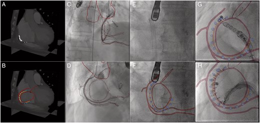
Prior to the intervention, the planning details (RCA, valve annulus, CS ostium, aortic root circle, trajectory) are marked in the pre-procedural CT (A). Subsequently, the planning details and required anatomical structures (e.g. aorta) are segmented (B). For better visibility of the trajectory, only the anchors of the Cardioband are segmented. Coregistration between XR and CT is obtained at the beginning of the procedure, based on RCA angiograms acquired in right anterior oblique (C) and surgical ‘en face’ orientation (D). In contrast to live XR fluoroscopy without augmentation (E), live XR fluoroscopy with augmentation is now provided throughout the procedure. Image fusion at different stages of the anchor implantation are shown in F (beginning), G (initial stage), and H (intermediate stage). Further interaction steps are limited to manual refinement of the registration during the procedure if required. Colour-coded overlay: anatomic landmarks (red), planned anchor positions (blue), trajectory (orange).
Peri-procedural image fusion
The procedure is performed conventionally in a hybrid catheterization lab in general anaesthesia under fluoroscopic and transesophageal echocardiographic guidance. During the procedure, additional to the standard configuration, the pre-procedural 3D CT-derived models and planning details are superimposed onto the XR fluoroscopy data (EP navigator Release 5.1.1.4, Philips Healthcare, Best, The Netherlands) and displayed side-by-side with the original XR fluoroscopy and TEE data in a separate window. The additional information is meant to provide anatomical details supporting efficient guidance of manoeuvring and anchor placement.
Coregistration between 3D CT and XR fluoroscopy is obtained from two angiographic views obtained in the right anterior oblique (Figure 1C) and in surgical ‘en face’ orientation (Figure 1D). Where a coarse initial coregistration is done by matching the projection of the 3D CT-derived model of the aorta with XR fluoroscopy, for fine-tuning the RCA is used as an anatomic landmark. Proper coregistration throughout the procedure is ensured by manual refinement based on a balance middleweight guidewire (Abbott Vascular, Wetzlar, Germany) positioned in the distal RCA.
How to use image fusion to assist navigation/representative results
Navigation during the procedure is assisted by the easier perception of the underlying anatomy derived by overlaying the planning data on the live XR fluoroscopy (Figure 1E,F). In general, the overlay of the anatomic landmarks and planning details is considered very helpful in illustrating the distance between RCA and the annulus. As indicated in Figure 1G, e.g. the planned anchor orientation can be adjusted by alignment of the orientation of the catheter with the superimposed 3D model of the anchor. The trajectory overlay (Figure 1G,H) is considered especially helpful. Even though the realized anchor positions are frequently adapted on-the-fly during the procedure, the trajectory overlay nicely reveals the anchor heads being still aligned to the trajectory, thus ensuring safe distance to the critical structures.
Discussion
With tools already approved for clinical routine, augmentation of the XR fluoroscopy by the patient-specific 3D planning details during cardioband TVR can be realized. The augmentation greatly facilitates the perception of the patient’s specific anatomy and thus may yield future reduction of procedure time. The combined display of the pre-planning with anatomical landmarks leads to a quick localization of the correct position of the first anchor. For the subsequent anchors, the trajectory and anchor alignment can be used as orientation. Additionally, the representation of the RCA in correlation to the annulus supports safe positioning of the anchors.
The accuracy of the image fusion and overlay is still limited. It is static and not adapted to the heart or respiratory movements visible in fluoroscopy. Further, the overlay is obtained from a pre-procedural CT, which may differ to the patient's specific volume load during the procedure. Hence in the presented approach, the fusion may not yet be suitable for final anchor placement and TEE is still required for accurate identification of the anchor position and orientation. Whether a side-by-side display of the TEE and the CT-XR fusion is sufficient, or more advanced fusion approaches e.g. combining CT, XR, and TEE may further improve navigation needs to be further investigated. However, CT-XR fusion has the potential to especially improve the initial positioning of the anchor and to restrict the application of TEE to the final implantation phase. Whether full compensation of cardiac and respiratory motion will be required in the end is still open. However, experiences made for other interventions such as TAVI5 imply that even without accurate motion compensation significant improvements regarding radiation and contrast dose, and procedure time could be achieved.
Even though exemplarily described for the Cardioband procedure and the EP navigator fusion software, the introduced approach can be generalized to other interventions and available CT-XR fusion software packages.
Considering the known geometry of the imaging system, in a further step, 3D reconstruction of the selected implant position of the anchors with subsequent visualization in the anatomic models and/or CT data may further facilitate anatomical correct implantation and documentation during the procedure.
In summary, the overlay of patient-specific 3D anatomical and planning data onto live fluoroscopy during cardioband TVR is feasible on a clinical system. Even though not yet motion-compensated and with only limited accuracy, the additional structural information facilities easier navigation.
Conflict of interest: none declared.
Acknowledgements
The authors would like to thank Mr Corc Savas (Edwards Lifesciences). The project on which this report is based was funded by the Federal Ministry of Education and Research under the funding code 13GW0372C. Responsibility for the content of this publication lies with the authors.
References
Author notes
Sinisa Markovic and Ina Vernikouskaya authors shared last authorship.
