


Abstract
Transcatheter tricuspid valve therapies are an emerging field in structural heart interventions due to the rising number of patients with severe tricuspid regurgitation and the high risk for surgical treatment. Computed tomography (CT) allows exact measurements of the annular plane, evaluation of adjacent structures, assessment of the access route, and can also be used to identify optimal fluoroscopic projection planes to enhance periprocedural imaging. This review provides an overview of current transcatheter tricuspid valve repair and replacement therapies and to what extent CT can support these interventions.
Introduction
An at least severe tricuspid regurgitation (TR) affects a rising number of patients in the industrialized world.1 Primary TR arises from intrinsic abnormalities in the valvular apparatus, whereas secondary or functional TR occurs predominantly as a result of left-sided heart disease and/or pulmonary hypertension.2 The tricuspid valve (TV) compromises an asymmetric saddle-shaped annulus, three attached leaflets (anterior, septal, and posterior), and a subvalvular supporting tension apparatus consisting of chordae tendineae and papillary muscles.3,4 Mediated by atrial and/or ventricular right heart enlargement, secondary TR results in an annular dilatation with a more circular and flattened shape.5 Furthermore, distortion of the spatial relationships among valvular components leads to leaflet tethering and malcoaptation.6 Secondary causes represent ∼90% of relevant TR cases and have been shown to have a poor prognosis if left untreated.7 A further differentiation between atrial TR (due to long-standing atrial fibrillation resulting an annular dilation) and ventricular TR [due to right ventricular (RV) dysfunction leading to RV remodelling with leaflet tethering] is of importance to define the optimal therapy approach (leaflet device, annuloplasty, or replacement) and also relates to the prognosis of the patient. To better characterize the extent of initial regurgitation and the effect of treatment, a novel grading scheme including five grades (additional Grade 4: massive and 5: torrential) has been introduced.1 There is a Class I recommendation for concomitant TV treatment in patients with severe TR undergoing left-sided valve surgery.8 In contrast, isolated TV surgery generally carries an increased mortality and morbidity burden due to an often incomplete assessment of the regurgitation pathophysiology and aetiology as well as RV function. Furthermore, the missing awareness of the medical community for the disease of the ‘forgotten valve’ leads frequently to a ‘too late’ instead of early referral of this patient group to minimal invasive therapy options.9 Therefore, many patients with severe TR who would benefit from valve repair or replacement therapy are restricted to conservative treatment. Thus, the need for a less invasive, transcatheter-based treatment approach is substantial. To date, several devices for interventional therapy have been developed, including leaflet repair and annuloplasty devices, heterotopic valve implantation in the caval veins and orthotopic transcatheter valve replacement. Additionally, percutaneous combination therapy has been reported.10 Replacement may provide a promising therapeutic option in suboptimal repair candidates or patients with massive TR. However, replacement approaches are still in development with a few ‘first-in-man’ experiences published.11,12 Given the complex TV anatomy and the specific interventional requirements, pre-procedural imaging is a key to a successful transcatheter treatment. This review provides an overview of the role of pre-interventional computed tomography (CT) imaging to support novel transcatheter TV therapies. It briefly sketches the different currently available transcatheter devices without any claim to completeness.
Multimodality imaging in patients with TR
Echocardiography is the first-line imaging modality for assessment of the aetiology and severity of TR and right heart chambers. However, the complex valve configuration in anterior location challenges the echocardiographer. Cardiac magnetic resonance tomography can assist in quantification of TR when echocardiographic assessment is insufficient. However, routine application is limited by restricted availability and contraindications. CT is particularly well suited for morphologic imaging of the heart. It offers a high spatial resolution with an excellent endocardial definition. CT’s isotropic resolution allows to reconstruct data sets in any desired plane without losing the ability to perform exact measurements.13 Multiphasic, cardiac-gated image acquisition provides an accurate evaluation of biventricular function and volumes.14
For planning TV interventions, CT imaging can provide several pieces of valuable information:
dimensions and morphology of the TV,
assessment of the device landing zone,
dimensions and function of the right ventricle (RV),
anatomic relationships with surrounding structures and possible impediments,
prediction of an optimal fluoroscopic projections for device implantation, and
assessment of the vascular access route.
Additionally, CT allows the concomitant evaluation of coronary, pulmonary, and thoracic conditions. However, radiation exposure and the need of iodinated contrast are drawbacks.
General aspects of CT image acquisition for transcatheter TV interventions
Specific acquisition requirements depend on the planned intervention and CT scanner, but some general principles should be taken into consideration:
Scanner system: multi-slice scanner systems (at minimum a 64-detector row scanner) should be used that provide a reconstructed slice width of 0.6–0.75 mm with a minimal increment.
Patient preparation: CT imaging should be ideally performed in a recompensated hydration state within a close time interval to the procedure. Beta-blocker use in patients with a heart rate >100 bpm is preferable.
Acquisition: standard anterior/posterior and lateral scouts of the thorax are performed. The cardiac window should extend from the tracheal bifurcation to shortly below the apex of the heart with complete coverage of the enlarged atria. A subsequent delayed non-gated scan with optimal venous opacification (∼70 s after the first scan) from the base of the skull to the groin for assessment of vascular access routes may be considered. The entire heart cycle should be registered allowing reconstructions every 5–10% of the R-R cycle. The available acquisition mode complies with the applied scanner system. Tube voltage and current settings should be chosen according to patient’s weight and size.15
Contrast administration: for optimal right-sided opacification, a simultaneous contrast injection should be ideally applied in both femoral and antecubital veins to avoid inhomogeneous enhancement of the right atrium and streak artifacts.16 For the sake of clinical reality though, a single right antecubital venous access route can be chosen to decrease possible streak artifacts caused from contrast crossing the mid-line.15 For optimal timing of contrast injection, a bolus tracking technique is frequently used (scan initiation threshold: 180 Hounsfield Units). Depending on the planned intervention and the need to visualize the right coronary artery (RCA) and its relation to the tricuspid annulus, the region of interest should be either placed in the middle of the RV (solely RV opacification) or in the proximal ascending aorta (RV and RCA opacification) with the contrast protocol tailored to ensure optimal right heart opacification. A triphasic injection protocol is recommended to minimize streak artifacts. Several approaches to provide excellent opacification of the right heart have been published.15,17 Our institutional contrast media protocol, which is specifically tailored to our institutional scanners and adopted from the method of Pulerwitz et al.,15 is provided in Table 1.
CT and contrast media protocol for optimal right heart opacification
| Total contrast volume (mL) | kV | mAS | Phase I (Contrast/ Saline) | Flow (mL/s) | Phase II | Flow | Phase III | Flow | Trigger (HU)/ scan delay (s) | |
|---|---|---|---|---|---|---|---|---|---|---|
| BMI <30 kg/m2 | ∼70 | 100 | Automatic | 90 (60/40) | 4 | 65 (25/75) | 4 | 20 (0/100) | 4 | 180/5 |
| BMI ≥30 kg/m2 | ∼75 | 120 | Automatic | 90 (60/40) | 4.5 | 85 (25/75) | 4.5 | 20 (0/100) | 4 | 180/5 |
Contrast protocols and kV/mAs settings should be tailored to scanner type and patient characteristics, e.g. scanners with longer scan time require a higher total contrast volume or young patients/patients with BMI <25 kg/m2 can be scanned with lower kV settings. For combined coronary and right heart opacification increase Contrast/Saline ratio in Phase I to 80/20, increase flow rate to 5 mL/s and decrease scan delay to 2 s.
HU, Hounsfield Unit; BMI, body mass index.
CT-based assessment of TV components
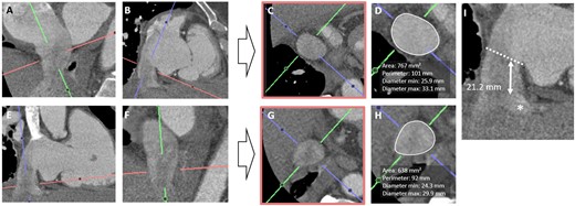
Using multiplanar reconstruction, a short-axis plane at the annular level can be reconstructed from RV two- and four-chamber views (Figure 1A–E). Cross-sectional area, perimeter, and anteroposterior and septolateral diameters can be obtained with excellent intra- and interobserver reproducibility being reported.5,18 For CT-based measurement, a mean perimeter of 148 ± 16 mm and mean area of 1612 ± 295 mm2 for patients with at least severe (TR grade ≥3) vs. 129 ± 13 mm and 1237 ± 257 mm2 in patients with TR grade ≤2 have been reported.19 Current patient treatment populations at our valve treatment centre exceed these values for massive or torrential TR by far. Given the dynamic change in annular size, measurements should be performed both in end-systole and mid-diastole.18 However, a major disadvantage of this 2D approach is that it does not accurately address the complex annular geometry. Systematic errors with underestimation of annular parameters derived from 2D compared with 3D measurements have been shown using a semi-automated software (3mensio Structural Heart, Pie Medical Imaging BV, Maastricht, The Netherlands).17 In a cross-validation study between transoesophageal echocardiography and CT, Praz et al.20 reported an optimal agreement for annular measurements between both modalities for a semi-automated approach. Perimeter was identified as the most reliable annular parameter for inter-modality comparison which is likely attributable to greater variations in area than perimeter over the cardiac cycle. Consequently, minor differences in the time point of measurement will result in higher differences in area than perimeter. In view of pre-procedural CT imaging, Praz et al.20 suggested that 3D-derived measurements may be favourable for annuloplasty planning as the device targets the nonplanar annular surface, whereas 2D-planar sizing may be more advantageous for replacement planning with sizing of a cylindrical transcatheter prosthesis. Semi-automated software approaches have been implemented for CT-assessment.21 After automated segmentation of the TV, the annulus is manually traced by selecting the hinge points (Figure 1F–J). Annotated dimensions are automatically calculated. Furthermore, assessment of the RCA course and its distance to the annulus, simulation of virtual device implantation, and prediction of an optimal projection angle are part of a comprehensive software-based pre-procedural assessment. The extent of leaflet tethering including tenting height, angle, and area can be assessed at mid-systole with a good to excellent intra- and interobserver variability being demonstrated (Figure 2).18 Though tricuspid calcification is an extremely rare finding, it should be reported if present, as this may majorly influence the success of direct annuloplasty and leaflet repair treatment.
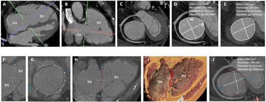
CT-assessment of the tricuspid annulus. (A–E) Manual approach: from a four- (A) and two-chamber views (B), a short-axis view of the tricuspid annulus is reconstructed (C). 2D-derived parameters in end-diastole (D) and mid-systole (E). (F–J) Semi-automated software-based approach: (F and G) After automated segmentation, the annulus is traced by selecting the hinge points (white dots). 2D- (H) and 3D-annular view (I). (J) Apical view of the annular plane in end-diastole: the commissures (anteroseptal, SA, pink; AP, blue; posteroseptal, SP; green) are depicted. Annular parameters are automatically calculated. AP, anteroposterior; RA, right atrium; RV, right ventricle; SL, septolateral.
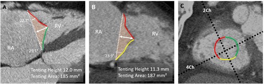
CT-assessment of leaflet tethering. (A) In a reconstructed RV four-chamber view, tenting height is measured as the distance between annular plane (dashed white line) and coaptation point between the anterior (red) and septal (green) leaflets. Tenting angle and area (orange-coloured area) can also be obtained in this view. (B) In a reconstructed two-chamber view, tenting angle for the posterior leaflet (yellow) and area is assessed. (C) Short-axis view of annulus. 4Ch, four-chamber plane; 2Ch, two-chamber plane; RA, right atrium.
Specific aspects of CT image acquisition for transcatheter TV intervention
Available transcatheter TV techniques include leaflet repair treatment, annuloplasty, heterotopic valve implantation in the caval veins, and orthotopic valve replacement (Figure 3). Depending on their respective location and anchoring mechanism, more comprehensive pre-procedural imaging may be required (Table 2). With the rising number of treatment approaches, we only included devices in an advanced stage of clinical study/trial or already approved, without any claim of completeness.
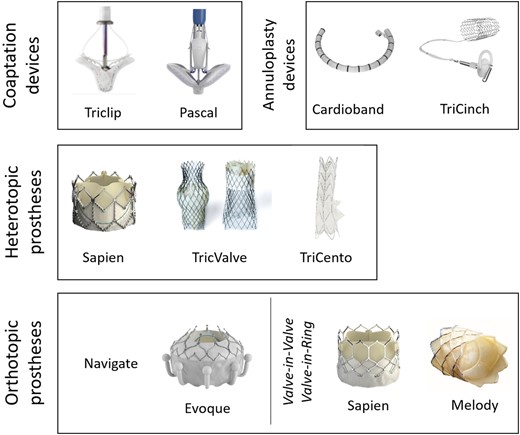
Devices for transcatheter tricuspid valve repair and replacement. No claim to completeness.
Reporting scheme for pre-interventional CT imaging before TV interventions
| Structure | Orientation and location | Parameter to report |
|---|---|---|
| Tricuspid annular dimensions | Short-axis view at annular level in
| Area Perimeter Anteroposterior and septolateral diameter |
| Course and distance of RCA | Short-axis view at annular level in end-systole and mid-diastole | Sub-, trans- or supra-annular course of RCA Minimal distance to tricuspid annulus
|
| Leaflet tethering | RV two- and four-chamber views | Height, area, angle of tenting |
| Right atrial and caval dimensions | RV two- and four-chamber views Double-oblique orientation:
| Atrium: Area and diameter IVC/ SVC: Maximal and minimal diameter |
| Tricuspid annular and subvalvular anatomy and abnormalities | Annular calcifications Distance between the RV apex and annulus Location of moderator band and prominent trabeculae | |
| Cardiac and non-cardiac incidental findings | ||
| Additional reportinga | ||
| Prediction of optimal projection angle | ||
| Dimension of coaptation defect | ||
| Virtual device implantation |
May require dedicated software solutions. Other specific measurements may be required, according to specific devices.
IVC, inferior vena cava; RCA, right coronary artery; RV, right ventricle/ventricular; SVC, superior vena cava.
‘Edge-to-edge’ and ‘edge-spacer-edge’ leaflet repair devices
Leaflet repair devices aim to improve the coaptation of tricuspid leaflets, thereby reducing the amount of regurgitation volume. Interventional Alfieri-styled ‘edge-to-edge’ repair has been successfully adapted from the mitral valve to the TV being the most commonly applied transcatheter method for treating TR.22 The Triclip system (Abbott Vascular, Santa Clara, CA, USA) is a grip device which grasps and coaptates the leaflets, thereby reducing the regurgitation area.23 The Pascal device (Edwards Lifesciences, Irvine, CA, USA) is an ‘edge-spacer-edge’ device and combines the idea of ‘edge-to-edge’ repair with a central spacer system to increase the native leaflet coaptation surface by occupying the regurgitant orifice area.24
Role of CT imaging
Pre-procedural CT imaging is not routinely performed for leaflet repair device implantation. However, if CT data are available, the dimensions of the coaptation defect and annulus should be assessed. Additionally, the anatomical relationship of the inferior vena cava (IVC) and the annulus can be examined as a very anterior or shallow entry of the vein challenges the operational distance between delivery system and leaflets.
Annuloplasty devices
Annuloplasty devices target annular dilation as the major pathophysiological mechanism in secondary TR by reducing the diameter either by a transfemoral ring- or suture-based approach.
The Cardioband (Edwards Lifesciences) consists of a flexible band that is anchored on the atrial side into periannular tissue starting adjacent to the RCA ostium following along the lateral annulus to the distal coronary sinus.25,26 For annular re-shaping, the band is then cinched, which results in a controlled reduction of anteroposterior and septolateral annular diameters. The Tricinch device (4Tech Cardio, Galway, Ireland) consists of a nitinol coil for annular fixation, a connecting tensioning band, and a stent in the IVC. After positioning the coil in the pericardial space close to the anteroposterior commissure, tension is applied to remodel the tricuspid annulus. The stent is then implanted into the IVC to maintain the desired tensioning and annular remodelling.27
Role of CT imaging
A major concern with annuloplasty devices is the risk of RCA spasm or injury as it runs closely to the tricuspid annulus. Therefore, assessment of the vessel course and distance to the annulus is routinely performed (Figure 4). The closest distance is found between the distal RCA and the posterior leaflet (mean horizontal distance 4 ± 3 mm) and the largest between the proximal RCA and the anterior leaflet (9 ± 5 mm).19,28 The vessel course in relation to the annulus is variable. An RCA course at the annular level has been shown in 65% of patients, a superior (i.e. atrial) course in 10% and a crossing course in 25%.19 Additionally, leaflet tethering should be assessed. Based on echocardiography, a tenting distance >0.76 cm and area >1.63 cm2 have been determined as critical thresholds for persistence of relevant TR after surgical annuloplasty.29 For the Cardioband, anchor placement based on proximity to the annulus, the wall, and the RCA can be simulated (Figure 5A–F). For the Tricinch device, CT evaluation includes the selection of an anchor implant location along the lateral region of the annulus and assessment of the IVC diameter for stent sizing (Figure 5G and H).
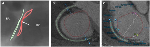
Tricuspid annulus in relation to the right coronary artery. CT-derived fluoroscopic (A) and short-axis view (B) of the tricuspid annulus (red line) and the RCA (green line) demonstrating a superior (atrial) course of the vessel in relation to the annulus. (C) Semi-automated assessment of distance from the tricuspid annulus to the RCA. RA, right atrium; RV, right ventricle.
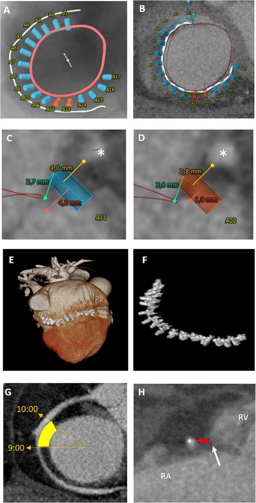
CT-assessment for annuloplasty intervention. (A–F) Cardioband: CT-derived fluoroscopic (A) and short-axis view (B) of the tricuspid annulus (red) with simulation of anchored device (white line with blue and orange anchors) in relation to the RCA (green). Blue anchors have a distance of at least 4 mm to the RCA (asterisk) (C), whereas orange anchors with a distance of <4 mm indicate a higher risk for RCA impairment (D). (E, F) Postprocedural 3D volume rendering data set with implanted cardioband device. (G, H) TriCinch device: (G) short-axis view of the tricuspid annulus, yellow area highlights the target zone for coil implantation (at 9:00 to 10:00). (H) Assessment of pericardial space distance (red double arrow) between RCA and annulus (white arrow) for coil implantation. RA, right atrium; RV, right ventricle.
Heterotopic caval valve implantation
Heterotopic implantation of valves in the caval veins aims on a reduction in blood backflow and prevention of systemic venous congestion.30 Balloon-expandable transcatheter aortic valve prostheses (Sapien XT, Edwards Lifesciences) were first applied after initial caval vein diameter reduction by a prior self-expandable stent implantation. The TricValve system (P&F Products and Features, Vienna, Austria) consists of two dedicated self-expanding valves, which are implanted in the superior and IVCs.31 The customized Tricento device (NVT AG, Muri, Switzerland) is deployed top down from the superior to the IVC without improving right atrial pressures nor the native TV function.32
Role of CT imaging
Dimensions of the IVC are measured at the transition level with the right atrium and at the level of the first hepatic vein in mid-systole (Figure 6). Furthermore, the distance between the junction plane of the IVC and right atrium and the first hepatic vein is measured to ensure for optimal valve positioning without hepatic vein obstruction. For the Tricento device, additional measurement of the right atrium is required.
CT-assessment for heterotopic valve implantation. Assessment of IVC dimensions (perimeter, area, and diameters) in a double oblique transverse plane at the transition level with the right atrium (A–D) and at the level of the first hepatic vein (D–F). Measurement of the distance between the junction plane of the IVC and right atrium (dashed line) and first hepatic vein (asterisk) to ensure optimal valve positioning without hepatic vein obstruction.
Orthotopic transcatheter TV prosthesis
With the overwhelming long-term results in transcatheter aortic valve replacement, transcatheter TV replacement for inoperable or high surgical risk patients is still in its infancy but raising large expectations.11,12 TV replacement is technically challenging due to the enlarged 3D-shaped annulus and the lack of calcifications providing a disadvantageous landing zone for the prosthesis. Furthermore, the annulus is dynamic with considerable modification in its diameter over the cardiac cycle.5 This may result in incomplete apposition of the prosthesis in the native annulus resulting in a possibly relevant paravalvular regurgitation. The theoretical advantage of TV replacement in terms of lower systolic pressures in the right heart is counteracted by the disadvantages of high annular size variability and delicate tricuspid leaflet tissue quality that necessitates dedicated valve systems. The AV node in the triangle of Koch is another TV specific vulnerable area that imposes bradycardia and pacemaker dependency in a relevant single-digit percentage of patients.
For the Gate bioprosthesis (NaviGate Cardiac Structures, Lake Forest, California) which is implanted via a 42-Fr large transjugular or transatrial access, an early single-site experience showed feasibility and safety.11 For the EVOQUE Tricuspid Valve Replacement System (Edwards Lifesciences) which is delivered through a 28-Fr transfemoral access, the first implantation has been recently reported and a clinical trial is underway (TRISCEND Study—NCT04221490).12
Transcatheter tricuspid valve-in-valve and valve-in-ring procedures are performed using either Sapien or Melody prostheses (Medtronic, Minneapolis, MN, USA). Due to device rotational orientation, the differences in effective inner diameters between ring types and radial forces on the implanted rings, we routinely confirm the effective 3D diameters in a preprocedural CT vs. the nominal size documented in the surgical report.33,34
Role of CT imaging
Assessment of valvular and subvalvular morphology for prosthesis sizing, vascular access route, and prediction of an orthogonal fluoroscopic angulation are key aspects in pre-procedural CT imaging (Figure 7). Given the large variety in shape of the developed prosthesis, specific sizing measurements will be subject to the particular valve. Pre-procedural planning can be additionally supported by virtual valve placement for assessment of implantation depth, prosthesis selection, and anchoring possibilities. Furthermore, distance between the RV apex and the annular plane and location of the moderator band and prominent trabeculae are of interest with regard to protrusion of the prosthesis into the RV during implantation. Assessment of the RV outflow tract can be considered. However, obstruction is of less concern than in transcatheter mitral valve replacement as the TV and inflow chamber is widely separated from the right outflow with pulmonary valve.
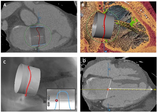
CT-assessment for orthotopic tricuspid valve implantation. (A) Virtual prosthesis implantation in the tricuspid annulus (right) for assessment of implantation depth, valve selection, and anchoring possibilities. (B) 3D-view visualizes possible interference of the device with trabeculae (green). (C) CT-derived simulated view for prediction of an optimal fluoroscopic projection angle. (D) Measurement of distance between annular plane (white-dashed line) and apex.
3D-printing and fusion imaging
3D-printing and fusion imaging offers an advanced imaging perspective for procedural planning and guiding. CT-based 3D-printing allows a stereometric visualization of the structure of interest and can be applied for prior hands-on simulation. Use of a 3D-printing model of the right heart structure for pre-interventional simulation of TV replacement has been reported.35 Fusion imaging integrates different imaging modalities on the same screen during the intervention, thereby combining their strengths and advantages for optimal procedural outcome.36 In the context of TV interventions, CT/fluoroscopy fusion imaging is applied for annuloplasty and transcatheter valve replacement (Figure 8).
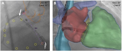
Fusion imaging for tricuspid valve interventions. (A) Annuloplasty: placement of first Cardioband anchor (arrow) supported by CT/fluoroscopy fusion imaging. Pink ring: right coronary artery ostium; orange outline: aortic root and ascending aorta; yellow rings: planned anchor placement. (B) Valve replacement: CT images of right atrium (red), right ventricle (green), caval veins (blue), and pulmonary veins (purple) are integrated into the live fluoroscopic views to support device positioning.
Summary
With the ongoing rise in complex TV interventions, procedural success highly depends on precise and comprehensive pre- and periprocedural imaging. CT imaging plays an important role in pre-procedural imaging for TV annuloplasty and replacement. Optimal opacification of the right heart structures requires specific CT protocols with adjustment of contrast injection. Assessment of the complex non-planar geometry of the annulus is challenging and can be supported by semi-automated software. CT data for 3D printing and fusion imaging may further support procedural planning.
Conflict of interest: F.K. reports having received speakers honoraria from Abbott Cardiovascular and Edwards Lifesciences. R.S.v.B. reports having received advisory board honoraria from Abbott Cardiovascular, Edwards Lifesciences, Boston Scientific, and Medtronic and trial steering committee and lecture honoraria from Abbott Cardiovascular and Edwards Lifesciences. All other authors have no conflicts of interest to declare.
