


Abstract
Duplex mode ultrasound imaging can detect the course of the main vascular structures in the face, which are known to be subject to variation. Once duplex mapping has been performed, measures can be taken to prevent injection into an artery, thereby avoiding skin necrosis or, worse, vision loss. For this reason, in particular, we predict that in the coming years sonography will become standard equipment in the offices of cosmetic doctors. We discuss the basics of vascular imaging by Doppler ultrasound, both in normal and pathologic situations. Starting from the 7 basic positions for the ultrasound probe, all facial arteries relevant in cosmetic medicine can be found.
Doppler ultrasound (DUS) is being promoted as a first-line imaging technique in cosmetic medicine. DUS can identify the location and depth of subcutaneous structures, as well as their 3-dimensional (3D) anatomic relations and the course of veins and arteries.1 Fillers are depicted as masses, being hypoechogenic (eg, hyaluronic acid) or hyperechogenic (eg, calcium hydroxyapatite).2-5 Filler complications such as inflammation, product migration, or vascular adverse events can also be visualized.4,6,7 Should the latter be caused by a hyaluronic acid fillers, hyaluronidase can be injected exactly into the errant filler deposit under ultrasound guidance.8,9 Part 1 of this study described standard anatomic positions that can be utilized as starting points to form a mental 3D image of the anatomy in every facial area. Here, attention will be directed to clinical application of DUS, specifically regarding safety in relation to vascular structures.
It is better to prevent vascular complications than to treat them. Vascular adverse events leading to skin necrosis, and in the worst case blindness, may occur when filler material is injected directly into the lumen of a vessel. To avoid this, sound knowledge of vascular anatomy is essential. However, variations in the course of every artery10-16 are known to exist and may also be acquired after trauma, surgery, or nonsurgical procedures of the face. DUS enables these variations to be observed before filler treatment is performed.17,18 Other structures to identify and avoid injecting into are the infraorbital and mental foramen in order to prevent functional impairments caused by compressing nerves or vessels and the parotid gland and duct.
As with many things, there is no meaning without context. Hence, there is little point in placing the ultrasound probe on an injection spot without assessing the whole picture of the area. Therefore, one should always begin at one of the standard positions and work from there to assess aberrant anatomy and the unexpected presence of vascular or other structures, eg, lymph nodes or old fillers. The standard positions in part 1 are chosen in such a way as to allow the physician to form a mental picture of the 3D structure of the area.
DUS Technique
The Doppler effect describes the observed change in frequency that occurs when a transmitter, eg, blood, has a different speed to that of an observer. Due to the movement of the transmitter the successive wave peaks are received at shorter intervals, causing an apparent increase in frequency by the observer.19 A well-known example of this phenomenon is provided by a train heading towards an observer, and the change in frequency of the whistle as it passes. In the case of DUS the moving blood cells transmit (in this case actually reflect) sound waves and move towards the transducer, which is the initial transmitter and at the same time the receiver (observer) of the sound wave.
With sonography, in this case in duplex mode, the angle of the transducer relative to the blood vessel is of importance. If the transducer is placed perpendicular to the vessel, no speed can be measured. The required angle can be created manually by tilting the transducer. In many machines, software can present the same feature by shifting the angles in the color box on the video screen. There will be a blue coloration of a blood flow moving away from the transducer and a red coloration when flow is towards the transducer.20 In cosmetic medicine, it is of no great importance which color is seen. However, in the case of occlusion, the vessel proximal to the blocking agent will become wider, a situation termed “hypervascularity.” Turbulence is seen as mixture of blue and red proximal to the occlusion. Collateral vessels expand, creating an image like a “Medusa head” with duplex ultrasound (Figure 1).
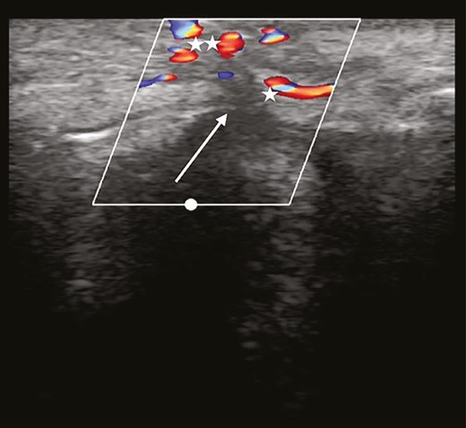
Complete occlusion. Turbulence is found proximal to the blocking agent. Collateral vessels increase in diameter, leading to a particular duplex ultrasound image, resembling a “Medusa head” (asterisk).
Veins can be distinguished from arteries by the absence of pulsations. In addition, veins are wider and can be compressed easily with the transducer to stop the flow. The parotid and submandibular salivary glands can be identified as homogeneous hyperechoic structures.
Standard Ultrasound Transducer Positions in the Face
For every area of the face a set of standard positions with a predefined orientation of the ultrasound transducer is defined. In these positions fixed anatomic structures (reference points) can be found easily. Starting from these reference points, the courses of the main vascular structures, and other structures relevant to the cosmetic physician, can be sought. The patient provided written consent for the facial examination. The examinations and study were conducted in accordance with guidelines of the Declaration of Helsinki as they are included in our standard of patient care.
Position 1: Jawline (Figure 2A-C)
• Reference point: masseter muscle
• Vascular structures: facial vein, facial artery, submental artery, external carotid artery
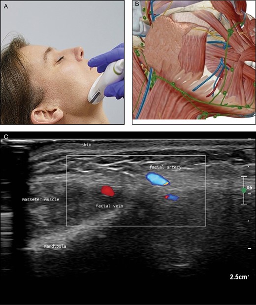
(A) Position of the probe on jawline. Female model; age, 39 years. (B) Anatomic overview of the structures visible in the ultrasound image Figure 2C. (C) Position 1: jawline. The facial vein (V) is ventral (medial) to the masseter muscle and the facial artery (A) is more ventral (medial) than the vein. The different colors are artifacts produced by the ultrasound device because of the rapid blood flow in the vessel (alienation).
The facial vein and artery can be picked up with the probe positioned transversely at the lower edge of the mandible, directly anterior to the masseter muscle. As will be apparent, the facial vein is a straight structure. Rotation of the transducer can visualize the vein along its length. Sliding medially, the facial artery can be seen as a small structure anterior to the vein (Figure 2). By sliding the probe cranially, the tortuous course of this artery can be followed and the origins of the inferior and superior labial arteries can be found close to the corner of the mouth. Returning to the edge of the mandibula again and following the facial artery in a caudal direction, the junction of the submental artery can be found below the lower edge of the mandible.
On top of the masseter muscle the parotid gland can be identified as a homogeneous, slightly hyperechoic structure (Figure 3). The external carotid artery can be identified posteriorly inside the gland. Inside the gland, the more or less horizontally running anechoic duct can be seen.
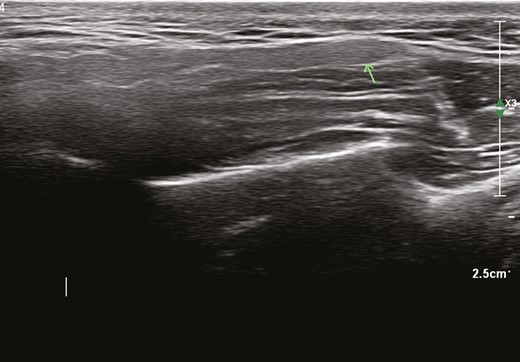
Homogeneous fine granular hypoechoic structure (arrow: parotid gland) on top of masseter muscle.
Technique Pitfalls and Recommendations
The tortuous aspect of the facial artery may be difficult to follow. Rotation of the probe, as described in Part 1, may help to follow its course.
Interpretation Pitfalls and Recommendations
The facial vein appears larger in diameter than the facial artery and may be misinterpreted. A vein is easy to compromise by compression with the ultrasound probe, whereas an artery is not.
Position 2: Chin and Lower Lip (Figure 4A-C)
• Reference point: depressor anguli oris muscle (DAO)
• Vascular structures: inferior labial artery, submental artery, mental artery

(A) Position of the probe on chin. Female model; age, 39 years. (B) Anatomic overview of the structures visible in ultrasound image. (C) Position 2: chin. Parts of the inferior labial artery can be seen superficial and deep to the orbicularis oris muscle.
The inferior labial artery can be found by placing the transducer on the edge of mandibular bone, then sliding upwards to end on the vermillion part of the lower lip (Figure 4). Rotational movements may be necessary because the artery can be very small. Once identified, the course of the artery can be backtracked to its origin at the facial artery. After picking up the submental artery at or below the mandibular rim (in position 1), we can follow its course medially, sometimes to the midline anastomosing with the mental artery and even the inferior labial artery. The mental artery can be identified emerging from the mental foramen, running anteriorly and medially.
Technique Pitfalls and Recommendations
The infralabial artery varies often in its individual course and instead of branching off from the facial artery, it branches off from the submental artery. If this artery is difficult to bring into sight, start from the lower lip and trace its course backwards
Interpretation Pitfalls and Recommendations
Follow the whole infraorbital artery to visualize whether the course is straight or whether it is tortuous and may run through several planes (and sometimes very superficial).
Position 3: Upper Lip (Figure 5A-C)
• Reference point: orbicularis oris muscle and teeth
• Vascular structures: superior labial artery, columellar artery
(A) Position of the probe on upper lip. Female model; age, 39 years. (B) Anatomic overview of the structures visible in ultrasound image. (C) Position 3: upper lip. A tortuous superior labial artery is running both superficial and deep to the orbicularis oris muscle (asterisk), resembling a “dancing snake.” In the blue parts the blood streams away from the probe; in the red part the blood streams towards the probe. Teeth are visible (double asterisk).
By sliding the ultrasound probe transversally along the edge of the lip, the plane and depth of the superior labial artery can be followed (Figure 5). Many variations exist because the course of these arteries may be subcutaneous, intramuscular, or submucosal. In some instances its course changes vertically to a different layer, giving it a tortuous course (looking like a “dancing snake”). The superior labial artery may give off branches to the nose. Place the transducer in the midline. By sliding cranially, a columellar artery, when present, can be seen.
Technique Pitfalls and Recommendations
If the supralabial artery turns out to have a tortuous aspect, it may be difficult to follow. Rotation of the probe, as descriped in Part 1, may help to follow it.
Interpretation Pitfalls and Recommendations
Because the columellar artery runs superficially and will be difficult to notice if the supralabial artery runs deep, it is necessary to change plane and look for it.
Position 4: Midface (Figure 6A-C)
• Reference point: zygomaticus major muscle
• Vascular structures: transverse facial artery, infraorbital artery, angular artery, lateral nasal artery
(A) Position of the probe on midface. Female model; age, 39 years. (B) Anatomic overview of the structures visible in ultrasound image. (C) Position 4: midface. The infraorbital artery enters the midface area through the infraorbital foramen (arrow).
Lateral from the zygomaticus major muscle at the lower edge of the zygoma bone, the usually small transverse facial artery can be picked up and followed to the midface area. The transverse facial artery can run inside the parotid gland. In the midpart of the face blood supply is provided by the angular, infraorbital, and transverse facial arteries in varying proportions.
The angular artery, being a continuation of the facial artery after giving off the superior labial artery, runs superficially and usually laterally to the nasolabial fold. However, a lot of variation exists. Cranial to the nasolabial fold the angular artery starts to run more medially and close to the nose. It gives off the lateral nasal artery to the alar nasi. The angular artery can be followed to the medial corner of the eye where it anastomoses with branches from the ophthalmic artery and the supratrochlear artery. The angular artery is not always present. In these cases a dominant infraorbital artery or a dominant transversal artery are responsible for the blood supply in this area. The infraorbital artery emerges from the infraorbital foramen, which is seen as a “gap” in the bone (Figure 6), generally 1 cm below the inferior orbital rim, slightly medial to the midpupilar line.
Technique Pitfalls and Recommendations
An infraorbital artery with a small diameter may not always be seen with a 12-MHz probe.
Interpretation Pitfalls and Recommendations
The infraorbital notch may appear as a discontinuation of the bone or as a small, black, oval structure with posterior enhancement.
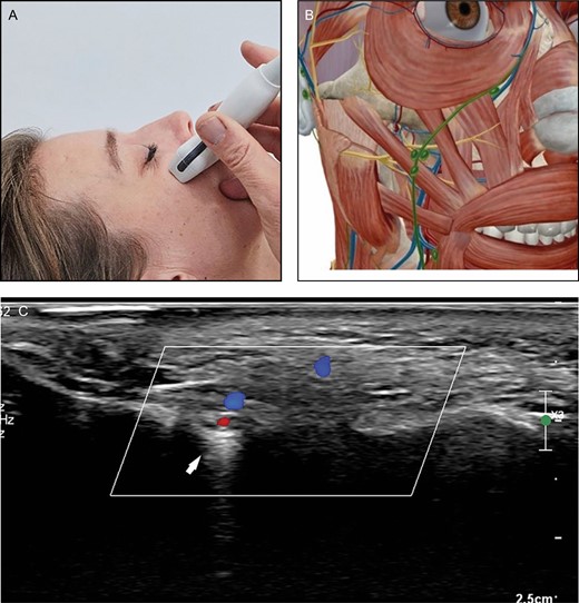
Position 5: Nose (Figure 7A-C)
• Reference point: nasal bone and cartilages
• Vascular structures: dorsal nasal artery, intercanthal vein, external nasal artery
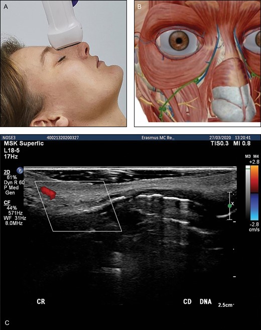
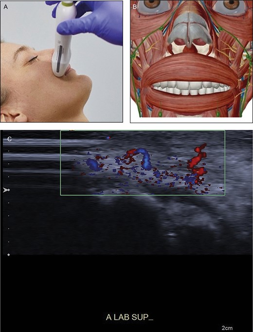
(A) Position of the probe on nose. Female model; age, 39 years. (B) Anatomic overview of the structures visible in ultrasound image. (C) Position 5: nose. Transverse position of the probe. DNA, dorsal nasal artery.
At the base of the nose we can identify the dorsal nasal artery on both sides (Figure 7). We can follow these to the tip of the nose. At the nostrils we can pick up the lateral nasal artery crossing the midsection of the nose. A columellar artery may be present, coming from the upper lip and supplying the nose tip. At the radix of the nose we can identify the intercanthal vein. It anastomoses with the vein from the contralateral side. Small venous structures may be identified draining the caudal part of the nose.
Technique Pitfalls and Recommendations
The shape of the nose is angled; a lot of ultrasound gel should be placed on the probe to make good contact. For Asian noses, a hockey stick may be advisable. Because the nasal vessels are small in diameter, no pressure should be applied with the probe
Interpretation Pitfalls and Recommendations
The intercanthal vein runs at the radix of the nose, connecting the angular veins bilaterally, is often found in the intercanthal line, and may be misinterpreted as the nasal artery. A vein is easy to compromise by compression with the ultrasound probe, whereas an artery is not.
Position 6: Temporal Area (Figure 8A-C)
• Reference point: temporal muscle
• Vascular structures: superficial temporal artery, zygomatico-orbital artery, frontal branch of the superficial temporal artery
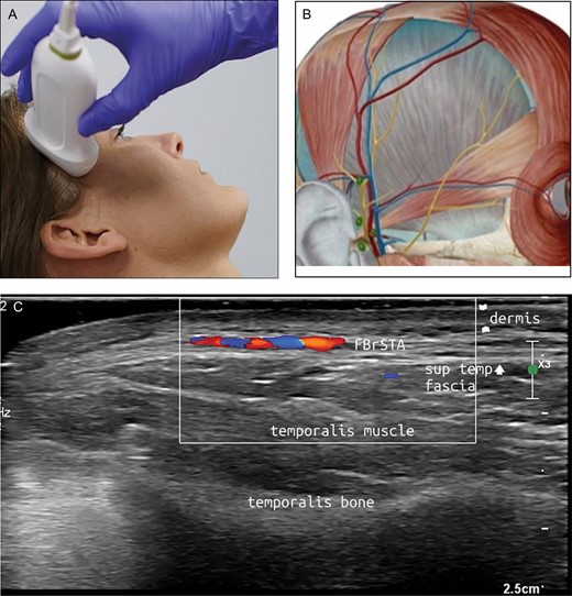
(A) Position of the probe on temporal area. Female model; age, 39 years. (B) Anatomic overview of the structures visible in ultrasound image. (C) Position 6: temporal area. FBrSTA, the frontal branch of the superficial temporal artery between the superficial and deep temporal fascia.
The superficial temporal artery, the zygomatico-orbital artery, and the frontal branch of the temporal artery form the main vasculature of the temples. These arteries run superficial to the temporal muscle. For the most part, the veins accompany their arterial counterparts.
With the probe placed in a longitudinal position, the superficial temporal artery can be most easily located at the very lateral side of the temporal area near the tragus of the ear. Sliding cranially, the first side branch above the zygoma is the zygomatico-orbital artery, an artery with different morphologies described. It may have an anastomosis with the ophthalmic artery, rendering it an important hazard when performing filler injections. The second branch is the frontal branch of the superficial temporal artery (Figure 8). The course of this branch can be traced to the lateral boundary of the frontalis muscle and the eyebrow. This artery anastomoses in small branches with the supraorbital artery.
The deep temporal arteries, anterior and posterior, ascend between the temporalis muscle and the pericranium. These arteries supply blood to the temporalis muscle and should be taken into account when injecting deep in the periost in this region.
Technique Pitfalls and Recommendations
The superficial temporal artery may run more laterally into the hairline. If not located in the current position, slide the transducer to a more lateral position.
Interpretation Pitfalls and Recommendations
To appreciate all the layers of the temples, start counting from above (skin) or underneath (bone).
Position 7: Forehead (Figure 9A-C)
• Reference: frontal bone and muscle
• Vascular structures: supraorbital artery, supratrochlear artery.
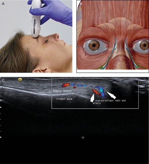
(A) Position of the probe on forehead. Female model; age, 39 years. (B) Anatomic overview of the structures visible in ultrasound image. (C) Position 7: forehead. The supraorbital artery runs above the corrugator muscle.
To pick up both supraorbital and supratrochlear arteries, the probe is positioned in a transverse position on the upper edge of the orbital rim (Figure 9). Because these arteries stem from the ophthalmic artery, they are a major concern for filler treatment in this area. At a certain distance cranial to the rim (usually 2 cm) the course of these arteries changes from deep (dorsal of the frontal muscle) to superficial (ventral of the frontal muscle).
Technique Pitfalls and Recommendations
A supraorbital artery with a small diameter may not always be seen with a 12-MHz probe; however, the notch can be seen easily. Sufficient ultrasound gel should be applied and pressure should be avoided
Interpretation Pitfalls and Recommendations
We recommend taking the point where the supraorbital artery and the supratrochlear artery penetrate the subcutaneous layer as the cutoff point where these arteries run superficial instead of deep.
DISCUSSION
The variability of the course of arteries in the face can easily be appreciated with the use of DUS in duplex mode.17,21 Both the depth and distribution of arteries may vary.22 If the course of the artery runs in a different plane than expected,18 the plane of injection can be adjusted accordingly. If the course turns out to be deviant, this can be marked on the skin before injection or under ultrasonography guidance, the blood vessels can be easily visualized, and the tip of the cannula or needle can be identified, thereby reducing the risk of intravascular infusion of filler. Vascular mapping with duplex mode before and during filler injections may diminish the risk of intra-arterial injections and will thereby increase safety.23 We believe that, over time, sonographic examination will be just as normal in cosmetic medicine as it is in phlebology. Fifteen years ago most phlebologists referred to radiologists to perform these examinations in their patients. Presently, at least in the Netherlands, all phlebologists perform DUS analyses of their patients themselves. However, one has to invest time and money when introducing DUS into daily practice.
Finally, there is an ethical component. In particular, when it is proved that DUS examination may prevent filler complications or will lead to better outcomes, physicians will be obliged to use the device. But, even at this moment in time, it seems to us that doctors performing filler injections have to gain as much knowledge as possible about the area in which they want to inject, and should perform DUS prior to their filler treatments.
CONCLUSIONS
DUS examination of the face visualizes the course of the arteries and veins. Before performing filler treatment, vascular mapping of the area to be treated can reveal the individual vascular variations. Should a vascular adverse event leading to skin necrosis occur, it may be helpful to monitor the process to detect the location of the adverse events; ultrasound-guided injections of hyaluronidase can be administered to restore flow if hyaluronic acid filler has been injected into a blood vessel. In this way, DUS may therefore increase the safety of filler treatments
Funding
The authors received no financial support for the research, authorship, and publication of this article.
Disclosures
Dr Kadouch is consultant for Merz Pharma (Frankfurt, Germany). Dr Schelke, Dr Velthuis, and Dr Jansen are trainers for Cutaneous, facial ultrasound (Noord, Holland). Dr Cotofana is consultant for Merz, Allergan (Dublin, Ireland), and Galderma (Lausanne, Switzerland). Dr Ascher is Scientific Director of the IMCAS.
Acknowlegments
The authors gratefully acknowledge Visible Body (Boston, MA) for the provision of the anatomical images that support the ultrasound images in this article.
REFERENCES
Author notes
Dr Velthuis is a dermatologist and Dr Schelke is a cosmetic physician, Department of Dermatology, Erasmus University Medical Center Rotterdam, Rotterdam, the Netherlands.
Dr Jansen is an intervention radiologist, Department of Radiology, Ommelander Ziekenhuis Groningen, Groningen, the Netherlands.
Dr Moon is a plastic surgeon in private practice, Seoul, South Korea.
Dr Kadouch is a dermatologist in private practice, Amsterdam, the Netherlands.
Dr Ascher is a plastic surgeon in private practice, Paris, France.
Dr Cotofana is an anatomist, Department of Clinical Anatomy, Mayo Clinic College of Medicine and Science, Rochester, MN, USA.

