


Abstract
Ultraprecise single-ion irradiation is of practical interest for the application of research and development of quantum materials and devices. To achieve this, a single-ion irradiation system, consisting of a linear Paul trap (LPT) and electrostatic bipotential lenses, is being developed at Takasaki Institute for Advanced Quantum Science, National Institutes for Quantum Science and Technology. In this paper, we conduct detailed multiparticle simulations on the controlled ejection of single ions from a two-component Coulomb crystal generated in the LPT, followed by the bipotential lens for strong focusing and acceleration of ejected cold ions, to investigate the feasibility of nanobeam formation. Two different schemes, which employ any of a string, planar, or shell crystal, are considered for selective single-ion ejection from the LPT. The present numerical results show that, in both ion ejection schemes, silicon ions sympathetically cooled through laser-cooled calcium ions can be ejected selectively from the LPT with an ultralow-emittance of the order of 10−15 m·rad or less and focused below 10 nm on the target after bipotential acceleration to 100 keV. The ion dynamics and focusing characteristics of the lens system are discussed.
1. Introduction
Focusing an energetic ion beam on the micro- and nanometer scale is an essential accelerator technology for various applications including local analysis, modification, and microfabrication of materials [1]. Especially, ultraprecise irradiation (or implantation) of single ions has gained more attention in the research and development of quantum materials and devices as a crucial means of introducing impurities and creating defects in materials on the nanometer scale [2,3]. An ultimate goal for these applications would be single-ion irradiation with nanometer-scale targeting precision and a high probability of achieving a controlled number of implanted ions. To achieve such small transverse size and targeting precision of the ion beam, the beam from an ion source or accelerator is often significantly collimated to reduce the effective emittance before final focusing [1]. Furthermore, a target sample may be masked by a pinhole for localized beam irradiation. However, this common approach to emittance reduction is limited, making controlled single-ion irradiation more challenging because of stochastic ion transmission in collimators and pinhole masks. Therefore, the development of a qualitatively different nanobeam formation method, which enables us to control an ultralow-emittance state more reliably independent of the conventional microbeam technology mentioned above, is important practically.
Here, we consider a precise single-ion irradiation method utilizing Coulomb crystals as an ultralow-emittance beam generator [4–6] for the several following reasons. A Coulomb crystal is an ultimate ordered state of charged particles, generated by the laser-cooling technique in an ion trap, where trapped ions cooled down to the mK range are well balanced between the external focusing force and the inter-ion Coulomb repulsion [7]. The emittance of a Coulomb crystal is theoretically almost zero and thus each ion is almost fixed at a specific position. Due to these characteristics, the existence of a small number of crystallized ions can be directly observed through laser-induced fluorescence and the individual ions can be manipulated reliably. Additionally, by applying sympathetic cooling [8], ions of various species (including highly charged ions and molecular ions) that are difficult to laser-cool directly can, in principle, be made ultralow-emittance through Coulomb collisions and, eventually, a multicomponent Coulomb crystal can be formed with laser-coolable ions. If such ultracold ions can be properly extracted from a trap and accelerated, a nanobeam can be formed with ultralow emittance. It was numerically shown that, by precisely controlling the confinement potential in the direction along the trap axis, cold single ions can be selectively extracted from a linear Paul trap (LPT) without significant emittance deterioration [9].
Regarding the fine focusing of cold ions extracted from an LPT, a few studies using an Einzel lens were carried out numerically and experimentally [5,10,11]. Recently, it was demonstrated that sympathetically cooled nitrogen ions can be extracted from a microfabricated trap by high-voltage switching and focused to the 100-nm level at 5.9 keV [12]. However, the dynamics in the process of ion extraction, acceleration, and focusing have not been studied in detail yet, especially in an acceleration-focusing system using bipotential lenses, which enables higher kinetic energies.
In this paper, we perform detailed 3D multiparticle tracking simulations to explore the nanobeam formation in a single-ion irradiation system combining a conventional four-rod LPT and electrostatic bipotential lenses, currently under development at Takasaki Institute for Advanced Quantum Science, National Institutes for Quantum Science and Technology (QST). We advance our previous studies of ion traps [9,13] and focusing lenses [14,15] to achieve precise single-ion irradiation in the higher-energy range of 50–100 keV. Heavy ions, such as nitrogen and silicon, in this energy range reach a relatively long penetration depth of around 100 nm in materials including diamond. This makes it possible to broadly control the quality and positioning of color centers created by ion implantation while mitigating the influence of surface conditions of the material [2,16]. We primarily choose Si as a possible ion species for precise irradiation since it is one of the ion species commonly utilized in ion implantation, e.g. for quantum applications including creation of color centers [16]. The entire process of single-ion irradiation is considered, from laser-cooling of trapped ions to focusing of extracted ions on the target. First, a two-component Coulomb crystal, composed of several Ca and Si ions, is generated sympathetically through laser-cooled Ca+ ions in the LPT, considering the Doppler cooling process under practical laser parameters such as intensity and detuning. Then, ultracold single Si ions are ejected selectively from the LPT by manipulating the axial potential barrier in two different ejection schemes according to the structure of the Coulomb crystal, and are ultimately accelerated and focused by the two-stage bipotential lens.
The paper is organized as follows: In Section 2, we first outline the single-ion irradiation system under development at QST Takasaki Institute. Multiparticle tracking simulation results on single-ion ejection and nanobeam formation are described in Section 3. Section 4 discusses the parameter dependence of the nanobeam formation on the bipotential lens voltage and the temperature of sympathetically cooled ions before ejection. Finally, the present results are summarized in Section 5.
2. Single-ion irradiation system
For later convenience, we make a brief explanation of our single-ion irradiation system here. A schematic overview of the system is shown in Fig. 1. In this simulation study, three main components are considered, i.e. a standard LPT for laser cooling and crystallization of trapped ions and ejection of cold ions, a two-stage electrostatic bipotential accelerating-focusing lens, and a target. Various species of ions, such as Si and N, will be provided from an external ion source (not shown in Fig. 1, as it is beyond the scope of this paper) to the LPT. For sympathetic cooling of ions supplied from the ion source, we adopt 40Ca+, whose Doppler limit is 0.54 mK, as a “coolant” ion species that can be directly laser-cooled.
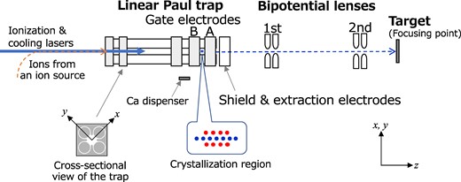
Schematic overview of the system setup for precise single-ion irradiation using a Coulomb crystal, under development at QST Takasaki Institute. Ions delivered from an external ion source (not shown) are captured and sympathetically cooled with laser-coolable Ca ions in the LPT (177.5 mm length in total). A two-component Coulomb crystal is prepared in the crystallization region (6.0 mm in length) between the Gate A and B electrodes for the controlled ejection of cold ions. The extracted ions are accelerated and focused on a target by a 50-kV two-stage electrostatic bipotential lens. The axial direction of the LPT is denoted by z and two transverse directions perpendicular to the z-axis named x and y. The origin of the z-axis is set at the center of the crystallization region between Gates A and B. The path length from the LPT center to the focusing point is approximately 400 mm. The cross-sectional view of the quadrupole and gate electrodes of the LPT is also depicted.
The electrical potential difference between the LPT and the grounded target, namely, the total extraction and acceleration voltage of the lens system, can be adjusted up to 50 kV. To reach an ion kinetic energy of 100 keV at the target, we also plan to use doubly charged ions (e.g. Si2+ and N2+) for irradiation in addition to singly charged ions.
2.1. LPT
The LPT is axially segmented into three regions: (i) a region for capturing ions from the external source, (ii) a region for generating and trapping Ca+ ions, and (iii) a region where a Coulomb crystal is prepared for ion extraction (denoted as the “crystallization region” in Fig. 1). The LPT consists of cylindrical quadrupole electrodes with a diameter of 6.88 mm and several gate electrodes with a thickness of 12 mm (except for the Gate A electrode, which is 17 mm thick) to confine ions in the transverse (x and y) and axial (z) directions, respectively. The distance from the trap’s z-axis to the quadrupole rods is 3.0 mm. The total length of the quadrupole electrodes is 177.5 mm, with the option to electrically divide them into two sections for efficient capture of ions from the external source. An rf voltage of 2.0 MHz is applied to the rod electrodes. The axial transport of ions between these segmented regions is managed using gate electrodes, to which a dc voltage of a few volts is applied. The axial length of the crystallization region, situated between Gate A and Gate B, is 6.0 mm. These gate electrodes are employed for the ejection of cooled ions from the LPT, as described later in Section 3. The ejected slow ions are electrostatically extracted (preaccelerated) to a few keV through a disk electrode with an aperture of 5.0 mm near the downstream end of the LPT to match the initial kinetic energy necessary for the bipotential lens system.
Doppler cooling (and ionization) lasers for Ca+ ions are directed along the z-axis (from the left side in Fig. 1).
2.2. Bipotential acceleration-focusing lens
The acceleration and strong final focusing of ions extracted from the LPT are achieved using the electrostatic two-stage bipotential lens, consisting of a pair of two parallel disk electrodes with an aperture [14]. The bore diameter and gap length of the first (second) lens are 2.0 mm (5.0 mm) and 2.0 mm (10.0 mm), respectively. The distance from the center of the crystallization region in the LPT to the first lens gap center is 113 mm, while the distance between the first and second lenses is 171 mm. A design study of the lens system will be detailed elsewhere (by Y. Ishii et al., manuscript in preparation).
The total length from the LPT center to the focusing point (target position) is approximately 400 mm. As demonstrated later, a relatively long working distance of about 80–100 mm, measured from the lower edge of the second lens electrode to the target where the ions are focused, can be achieved by selecting appropriate gap voltages G1 and G2 applied to the two lenses.
It is worth noting that the present system is operated electrostatically as much as possible (except for rf focusing of the quadrupole rods and ejection using the gate electrode) to prevent unwanted heating of laser-cooled ions during extraction and acceleration.
3. Simulations of single-ion ejection, acceleration, and focusing
Systematic tracking simulations are performed to investigate the ion behavior from ejection to acceleration and focusing. For this purpose, we utilize a 3D multiparticle tracking code developed for ion traps and related systems. The original code integrates the equations of ion motion in a symplectic manner, taking Coulomb interaction among individual ions into account [9]. The effect of collisions with background gases is ignored for simplicity. The external electrical potential data are provided by CST Studio Suite [17], assuming the actual 3D electrode configuration of the irradiation system. In addition, it is possible to simulate the Doppler cooling process in consideration of such parameters as laser power and detuning, which enables us to make a reliable estimate of the achievable beam size on the target. The laser cooling force incorporated in the present tracking simulation is outlined in Appendix A. In the following, we mainly consider 28Si as a possible irradiation ion species (unless otherwise noted) useful for ion implantation in some quantum applications [16]. A sufficient number of Ca+ ions are trapped simultaneously for sympathetic cooling of Si ions.
To properly eject only a Si ion from the LPT while preventing the ejection of unwanted Ca+ ions, we here employ two different schemes of ion-selective ejection [9]. One is a fast ejection scheme, where the voltage of the Gate A electrode is rapidly switched. The other is a slow ejection scheme, where the voltage of Gate B is gradually increased over a long period of milliseconds.
3.1. Fast ejection scheme
3.1.1 Use of a string crystal
We first focus on the simplest structure of a Coulomb crystal, i.e. a string crystal, where trapped ions are aligned one-dimensionally on the trap’s z-axis. As already studied in Refs. [9,13], a condition on the ion configuration of a two-component string crystal must be fulfilled for successful fast ejection without serious collisional heating: One irradiation ion (here, Si+) must be positioned at the leading end of the crystal along the ejection direction in the crystal. For this purpose, the axial ion configuration of a two-component string crystal must be arranged, while it is generally random. Experimentally, it is possible to change the configuration by modulating the dc gate voltage for axial confinement and/or laser cooling force. Otherwise, the ion configuration can also be controlled by exciting vibrational modes [18]. Once the desired configuration is achieved, the ejection process is initiated. For the sake of simplicity, we have, therefore, chosen the case of such an equilibrium configuration (as shown in Fig. 2) among several cooling simulations with random initial conditions. In the simulation, the rf rod voltage Vrf and the dc voltage VA = VB of Gates A and B have been set to 30 V and 0.5 V, respectively. Two Ca+ ions were Doppler-cooled with modest laser parameters of a peak saturation parameter S0 = 0.1 and a detuning δ = −24 MHz, and one Si+ ion was sympathetically cooled via Coulomb collisions with the laser-cooled Ca+ ions. In the equilibrium state after sympathetic cooling is completed, the temperatures of the Si+ ion were 0.9 mK and 1.1 mK in the two (x and y) transverse directions, respectively. The corresponding normalized root-mean-squared (rms) emittances of the Si+ ion are 1.8 × 10⁻¹⁵ m·rad and 2.2 × 10⁻¹⁵ m·rad in the x- and y-directions, respectively.
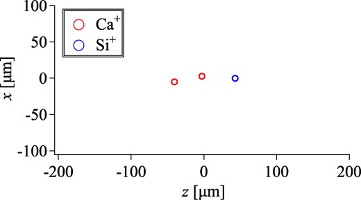
Spatial distribution of a two-component string crystal. Each red (blue) circle represents a single Ca+ (Si+) ion. The confinement condition of the LPT is Vrf = 30 V and VA = VB = 0.5 V.
In order to selectively eject only the leading Si+ ion toward the target, the voltage VA of Gate A is rapidly manipulated. First, the voltage VA is switched off (within 0.2 µs) to initiate the downward motion of all three ions. Then, VA is quickly returned to 0.5 V at an appropriate timing, preventing the two following Ca+ ions from passing through Gate A [9]. The time evolution of the ions’ position along the axial direction during this VA manipulation is shown in Fig. 3.
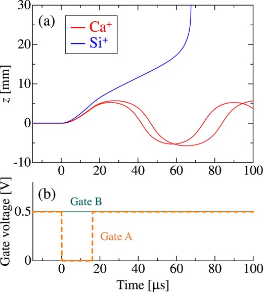
(a) Temporal evolution of the axial coordinate z of the three ions in Fig. 2 and (b) the corresponding timing diagram of the gate voltages VA and VB during fast ejection. The origin of the abscissa is the time when the Gate A electrode is promptly switched off. Only the leading Si+ ion is ejected from the LPT toward the target while the two following Ca+ ions are reflected backward after the recovery of the Gate A voltage VA to 0.5 V at 16 μs. Note that the Gate A electrode (17 mm in length) is located at 3 mm ≤ z ≤ 20 mm.
To evaluate statistical properties such as the emittance and spot size of the single Si+ ions ejected from the LPT, 100 independent ejection simulations were performed using randomly different initial conditions. The transverse trajectories of three ions arbitrarily chosen among them are plotted along with the kinetic energy in Fig. 4. After ejection, the single Si+ ions have a beam waist at the axial coordinate z ≈ 29 mm due to quadrupole focusing of the LPT, and then are preaccelerated to 2.5 keV by the extraction electrode with a voltage Vext set to −2.5 kV to match the kinetic energy for the subsequent bipotential lens system. The normalized rms emittance of the extracted ions remains almost unchanged from the values in the LPT, which indicates little collisional heating during the fast ejection.
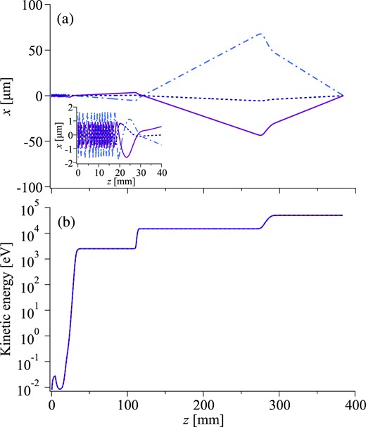
(a) Transverse trajectories and (b) kinetic energy of three Si+ ions arbitrarily chosen from 100 independent ejection simulations along the axial coordinate z. The inset in (a) is an enlarged view of the trajectories from the LPT to the extraction electrode. The extraction and acceleration voltages are as follows: Vext = −2.5 kV, G1 = 12.5 kV, and G2 = 35 kV. Namely, for singly charged ions, the extracted ions are extracted at 2.5 keV and then accelerated to 15 keV by the first bipotential lens and finally to 50 keV by the second. The kinetic energies of the three ions are almost identical. The slight deceleration at z ≈ 5 mm is due to the recovery of the Gate A voltage VA to 0.5 V at 16 μs (see Fig. 3).
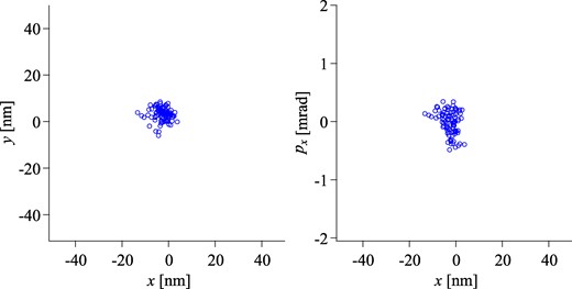
Next, the 2.5-keV Si+ ions proceed through the two-stage bipotential lens system toward the target. The ions are initially overfocused toward the second lens by the first bipotential lens. The final focusing is achieved by the second lens. In the case of gap voltages G1 = 12.5 kV and G2 = 35 kV, the beam waist is formed at an axial coordinate of z = 384 mm, providing a working distance of 84 mm. The ion distribution at the position is shown in Fig. 5. Rms spot sizes of 6.1 nm and 4.7 nm are achieved in the x- and y-directions, respectively. A weak aberration effect was observed in the second bipotential lens, where the transverse amplitude of the ion is relatively large as shown in Fig. 4. Therefore, the normalized rms emittances on the target have been slightly increased to 3.3 × 10⁻¹⁵ m·rad and 3.0 × 10⁻¹⁵ m·rad in the two transverse directions, respectively.
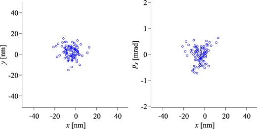
Transverse cross-sectional and phase-space distribution of the 50-keV Si+ ions at a waist position of z = 384.00 mm. One Si+ ion sympathetically cooled with two Ca+ ions (see Fig. 2) is selectively ejected from the LPT by switching VA quickly and then accelerated up to 50 keV through the two-stage bipotential lens. The conditions of the extraction and acceleration voltages are the same as those in Fig. 4. The results of 100 independent simulation runs are plotted. The ordinate px of the right panel represents ions’ angle in the x-direction.
3.1.2 Use of a planar crystal
Another crystalline structure suitable for fast ejection is a 2D planar crystal. The structure and spatial extent of a Coulomb crystal depend on the focusing strength in all three directions as well as on the number of confined ions. When the focusing force in the axial direction is sufficiently stronger than that in the transverse direction, crystallized ions tend to spread transversely rather than axially [7]. Such distinct crystals were generated experimentally [19]. Moreover, for a two-component crystal, ions with a lower mass-to-charge ratio are more strongly focused and thus naturally settle closer to the trap axis, while heavier ions are spread out transversely [20]. The advantage of using a planar crystal for the ion-selective ejection is that we do not have to control the axial configuration of the ejection ion with a lower mass-to-charge ratio, unlike the case of the string crystal (Fig. 2).
In the case of relatively weak transverse focusing (Vrf = 10 V) and few ions (five Ca+ and one Si+ ions), we have confirmed that the configuration of a two-component crystal is planar for strong axial focusing of |${V}_{\rm{A}} = {V}_{\rm{B}} \mathbin{\lower.3ex\hbox{$\buildrel>\over {\smash{\scriptstyle \sim}\vphantom{_x}}$}} 1.2$| V. An example of a planar-like crystal is shown in Fig. 6 where one Si+ ion is fixed on the trap’s z-axis and five Ca+ ions are arranged transversely in a ring shape. Note that, in this example, the six ions (including the Si+ ion) are not perfectly aligned at z = 0 since the gate voltage has been slightly reduced to VA = VB = 1.0 V to make the temperature of the Si+ ion lower.
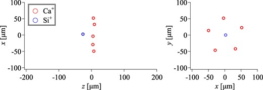
Spatial distribution of a two-component planar-like crystal. Each red (blue) circle stands for a single Ca+ (Si+) ion. The confinement condition of the LPT is Vrf = 10 V and VA = VB = 1.0 V.
Similarly to the string-crystal case (Fig. 3), we have confirmed that only the Si+ ion can be selectively ejected from the LPT to the target by controlling VA at proper timing since the lighter Si+ ion passes through the Gate A electrode earlier than the five Ca+ ions. Under the same extraction and acceleration condition, an ion distribution similar to that shown in Fig. 5 has been obtained on the target (see Appendix B).
3.2. Slow ejection scheme
Next, we study the slow ejection scheme using a two-component shell crystal, where ions with a lower mass-to-charge ratio are localized along the trap axis, surrounded transversely by ions with a higher mass-to-charge ratio due to the difference in the focusing force being dependent on the mass-to-charge ratio, like in the planar-crystal case. As explored in Ref. [9], the dc voltage of the Gate B electrode, which confines ions axially, is slowly increased to selectively eject the ion(s) with a lower mass-to-charge ratio. Due to the gradual deformation of the axial potential, the leading ion (or potentially a few additional ions, depending on the final Gate B voltage and the number of trapped ions) can be adiabatically ejected from the LPT. We here consider doubly charged Si2+ as an irradiation ion species for two main reasons: The more significant difference in the mass-to-charge ratio from Ca+ seems to promote the formation of a shell crystalline structure that facilitates ion-selective ejection. Additionally, highly charged ions can be easily accelerated to higher kinetic energy for deeper penetration into a target sample.
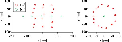
An example of a two-component shell crystal is shown in Fig. 7, containing 18 Ca+ and 5 Si2+ ions. In this case, the rf voltage of the rods and the dc voltage of Gates A and B have been set to 15 V and 1.0 V, respectively. Axial laser cooling has been applied with S0 = 0.1 and δ = −24 MHz. The equilibrium normalized rms emittance of the Si2+ string inside the Ca+ shell is 7 × 10⁻¹⁶ m·rad in the transverse direction. The leading Si2+ ion (the rightmost ion in the z-x profile in Fig. 7) is ejected from the LPT after the voltage VB of Gate B is linearly increased from 1.0 V to 22.15 V over a period of 20 ms, 4 × 10⁴ times the rf period. The time evolution of the ion position during the VB ramp-up is shown in Fig. 8. After the completion of VB ramping over 20 ms, only the leading Si2+ ion is ejected toward the target, while the remaining 18 Ca+ and 4 Si2+ ions are retained inside the asymmetric axial potential barrier of the LPT. The ejected ion is then focused onto the target via the extraction electrode and the two bipotential lenses. The emittance of the slowly ejected ions is slightly worsened to 9 × 10⁻¹⁶ m·rad.
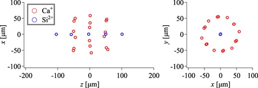
Spatial distribution of a two-component shell crystal. Each red (blue) circle stands for a single Ca+ (Si2+) ion. The confinement condition of the LPT is Vrf = 15 V and VA = VB = 1.0 V.
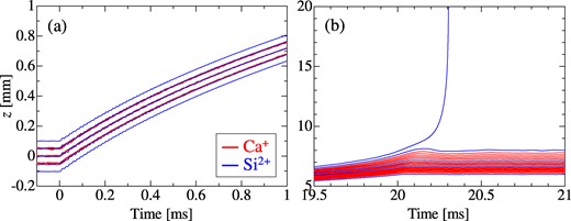
Temporal evolution of the axial coordinate z of Si2+ and Ca+ ions during slow ejection using the shell Coulomb crystal in Fig. 7. (a) Around the beginning of VB ramping. (b) Around the end of VB ramping. The origin of the abscissa is the time when the ramp-up of the Gate B voltage is initiated. The voltage VB is linearly increased from 1.0 V to 22.15 V with time over 20 ms, while other trapping voltages are fixed at Vrf = 15 V and VA = 1.0 V.
The final ion distribution at the waist position is displayed in Fig. 9. The beam waist position (at z = 384.00 mm) coincides with the previous fast ejection case (Fig. 5) under the condition of identical extraction and acceleration voltages (Vext = −2.5 kV, G1 = 12.5 kV, and G2 = 35 kV), despite the different ejection scheme. This indicates that the difference in the ion velocity which depends on the ejection scheme is effectively compensated by the relatively high-voltage extraction of −2.5 kV. The normalized rms emittances of the 100-keV Si2+ ions were found to be 1.6 × 10⁻¹⁵ m·rad and 1.5 × 10⁻¹⁵ m·rad in the x- and y-directions, respectively, due to lens aberration, and the corresponding rms spot sizes were 3.0 nm and 2.7 nm, respectively.
Transverse cross-sectional and phase-space distribution of the 100-keV Si2+ ions at a waist position of z = 384.00 mm. The leading Si2+ ion sympathetically cooled with Ca+ ions is selectively ejected from the LPT by increasing VB gradually (see Fig. 8) and then accelerated up to 100 keV through the two-stage bipotential lens. The conditions of the extraction and acceleration voltages are the same as those in Fig. 5. The results of 100 independent simulation runs are plotted.
We have also confirmed that, for 14N2+ (in place of Si2+), a two-component shell crystalline structure similar to that in Fig. 7 can be formed by sympathetically cooling N2+ ions with Ca+ ions and that single N2+ ions extracted from the LPT can be focused to an rms spot size below 10 nm. These numerical results are summarized in Appendix C.
4. Focusing properties
Understanding how the nanobeam formation using ultracold ions extracted from the LPT is influenced by various conditions of extraction and acceleration and the ion characteristics is practically important for measuring and tuning the target position and spot size in upcoming experimental studies. We have, therefore, explored focusing properties depending on the applied voltages of the extraction and acceleration electrodes, and found that they have similar tendencies. In the following, we only present simulation results on the gap voltages G2 of the second bipotential lens.
Figure 10(a) illustrates the dependence of the ions’ rms spot size measured at a specific axial coordinate on the gap voltage G2 of the second bipotential lens. The minimum spot size less than 10 nm is achieved for G2 = 35 kV, as demonstrated in the previous section. We have found that the spot size is almost linearly dependent on G2 separately below and above G2 = 35 kV, with a slope of 1.2 nm/V. This tendency indicates that the fluctuation of the lens voltage must be controlled to an order of 10−5 (or less) to maintain stable nanobeam formation.
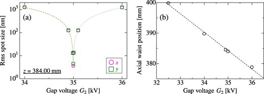
(a) Gap voltage G2 dependence of the transverse rms spot size of the ions measured at a specific axial point of z = 384.00 mm. Dashed and dotted lines correspond to the linear-fitting results evaluated separately below and above G2 = 35 kV, respectively. (b) Gap voltage G2 dependence of the waist position where the spot size of the ions is minimized below 10 nm. A dashed line corresponds to the linear-fitting result. Other extraction and acceleration conditions are fixed at Vext = −2.5 kV and G1 = 12.5 kV.
Another example exhibiting voltage dependence is the axial waist position where the transverse spot size of the focused ions is minimized. As shown in Fig. 10(b), the waist position shifts linearly with G2 at a rate of −6.0 μm/V and can be adjusted by more than 20 mm. This enables a long working distance, adjustable between 80 and 100 mm, allowing placement of a target sample sufficiently far away from the high-voltage electrode.
The transverse spatial extent of the focused ions is also affected by the emittance of cooled ions prior to ejection from the LPT. To explore this, the equilibrium emittance of the two-component shell crystal in Fig. 7 was degraded by randomly kicking the crystal and detuning the frequency of the cooling laser. As shown in Fig. 11, the achievable minimum spot size clearly depends on the equilibrium emittance (temperature) of the sympathetically cooled ions. When the ions are below 1 × 10⁻¹⁴ m·rad (or 10 mK), the ions can be focused to 50 nm or less. However, at higher emittances, the spot size increases due to aberration in the bipotential lens under the current acceleration conditions. Moreover, we have also found that, for the slow ejection scheme, the probability that only the leading Si2+ ion is ejected from the LPT is decreased at higher emittances. If we try to eject the leading ion at a probability of 100%, one or more proceeding ions are also ejected.

5. Summary
We have conducted detailed multiparticle tracking simulations to study the feasibility of nanobeam formation using a Coulomb crystal, an ultralow-emittance ordered state of trapped ions generated via the Doppler laser-cooling technique. The system considered here for precise single-ion irradiation consists of a standard LPT and a 50-kV two-stage electrostatic bipotential lens system, which enables controlled ion ejection and strong beam focusing across a wide range of kinetic energies. Various species of ions can, in principle, be made ultralow-emittance with sympathetic cooling in the LPT. Aiming for a practical example relevant to quantum technologies, we have primarily chosen silicon as a possible irradiation ion species.
Depending on the number of trapped ions and confinement conditions, different structures of two-component Coulomb crystals suitable for selective ion ejection can be sympathetically formed with directly laser-cooled Ca ions, including not only string and shell crystals but also planar crystals. Notably, the use of planar and shell two-component crystals has the advantage that ions with a lower mass-to-charge ratio naturally settle along the trap z-axis. Therefore, we can selectively separate a Si ion from such a two-component Coulomb crystal without caring about its configuration, unlike the string-crystal case, which requires the artificial control of the Si ion position for ion-selective ejection. We have considered two ion-selective ejection schemes in this study. In the fast ejection scheme using a string or planar crystal, a single Si ion, moving faster than Ca ions, can be reliably launched from the LPT by quickly switching the gate electrode voltage. On the other hand, the leading ion can be adiabatically pushed out beyond the gradually changing axial potential barrier in the slow ejection scheme.
The ultracold Si ions ejected from the LPT are extracted at an appropriate initial energy and eventually accelerated to 50 keV (100 keV for doubly charged ions) by the two-stage 50-kV electrostatic bipotential lens toward the target. A minimum rms spot size of 3 nm is achieved on the target without relying on collimation. The normalized rms emittance of the nanobeam corresponds to the order of 10−15 m·rad, although the emittance is slightly deteriorated due to aberrations of the second lens in the present acceleration condition. Surveying the effect of the applied voltage of the bipotential lens, we have found that the sensitivity of the spot-size change to the second lens’s voltage is 1.2 nm/V, which requires stability on the order of 1 V or lower for fine-tuning the minimum spot size. Similarly, the waist position axially shifts at a rate of −6 μm/V. A long working distance of 100 mm can be attained by adjusting the voltage applied to the bipotential lens. The achievable spot size of the focused ions depends on the emittance (temperature) of the sympathetically cooled ions before ejection. Our simulation results suggest that, when trapped ions are cooled below 1 × 10⁻¹⁴ m·rad or 10 mK in the LPT and properly accelerated by the lens system, the rms spot size of the focused ions can be on the order of 10 nm or less. The present results will open up the way to achieving nanometer-scale ion irradiation (implantation) at higher energies for quantum technologies including precise creation of color centers in materials.
Funding
This work was supported in part by a Japan Society for the Promotion of Science (JSPS) KAKENHI Grant No. JP20H00145 and by a Japan Science and Technology Agency (JST) Moonshot R&D Grant No. JPMJMS2062.
Appendix A. Doppler cooling force
In the multiparticle tracking code used for this study, a realistic Doppler laser-cooling process can be incorporated. The dissipative force generated by a laser light is evaluated from the following form [21]:
where |$\hbar {{\bf k}}$| is the photon momentum with k being the wavenumber vector of the laser, |${\rm{\Gamma }}$| is a natural line-width of the cooling transition, S is the saturation parameter, |$\delta $| is the frequency detuning of the laser, and v is the velocity vector of an ion.
In the present study, to cool ions confined in the LPT, we simply inject a single laser along the trap’s z-axis from the upstream direction as depicted in Fig. 1. A Gaussian laser intensity distribution is assumed with a saturation parameter |$S = {S}_0\exp [ { - 2( {{x}^2 + {y}^2} )/{w}^2} ]$|, where |${S}_0$| and w correspond to the peak intensity and spot size of the laser, respectively. A spot size of w = 1 mm has been chosen on the basis of our experimental study.
The Doppler cooling limit is determined by the equilibrium between the above dissipative force and diffusion originating from stochastic photon absorption and emission. We have confirmed that the correct Doppler limit is reached in our Monte Carlo method.
Appendix B. On-target distribution of ions ejected from a planar-like crystal
The on-target distribution of Si+ ions selectively ejected from the planar-like crystal (Fig. 6) by the fast ejection scheme is shown in Fig. B1. Rms spot sizes of 9.4 nm and 8.3 nm are achieved in the x- and y-directions, respectively.

Transverse cross-sectional and phase-space distribution of the 50-keV Si+ ions at a waist position of z = 384.00 mm. One Si+ ion comprised in the planar-like crystal (Fig. 6) is selectively ejected from the LPT by switching VA quickly and then accelerated up to 50 keV through the two-stage bipotential lens. The conditions of the extraction and acceleration voltages are the same as those in Fig. 5 except for the recovery timing of VA at 11 μs. The results of 100 independent simulation runs are plotted.
Appendix C. Case of nitrogen ions
Nitrogen is also an important species of ion implantation, e.g. for color center creation in diamond [2]. It is, thus, worthwhile to mention the feasibility of achieving the selective ejection and focusing of nitrogen ions using our system. We have confirmed that various two-component crystals can be formed with laser-cooled Ca+ ions by properly choosing the trapping voltages and the number of trapped ions. An example of a two-component shell crystal is shown in Fig. C1. For efficient confinement and cooling of N2+, the trapping voltages have been adjusted to lower values, Vrf = 10 V and VA = VB = 0.5 V, and more powerful laser cooling has been applied with S0 = 1 and δ = −48 MHz, as compared to the case of Si2+ (Fig. 7). The equilibrium normalized rms emittance of the N2+ string inside the Ca+ shell is 1.3 × 10⁻¹⁵ m·rad in the transverse direction.
Spatial distribution of a two-component shell crystal, containing 18 Ca+ and 5 N2+ ions. Each red (green) circle stands for a single Ca+ (N2+) ion. The confinement condition of the LPT is Vrf = 10 V and VA = VB = 0.5 V.
Similarly to the case of Si2+, only the leading N2+ ion (the rightmost ion in the z-x profile in Fig. C1) can be ejected out of the shell crystal by slow increase of VB. The on-target distribution of focused ions is shown in Fig. C2. Here, the gate voltage VB has been sufficiently slowly (during 10 ms) increased from 0.5 V to 10.98 V. The normalized rms emittances of the 100-keV N2+ ions are 3.1 × 10⁻¹⁵ m·rad and 4.0 × 10⁻¹⁵ m·rad on the target in the x- and y-directions, respectively, and the corresponding rms spot sizes are 3.6 nm and 4.5 nm, respectively. We have confirmed that the waist is formed at almost the same axial position under identical extraction and acceleration conditions (Vext = −2.5 kV, G1 = 12.5 kV, and G2 = 35 kV) although the LPT’s confinement and ejection voltages differ from those used in the Si case.
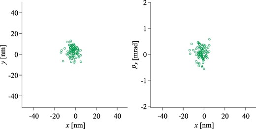
Transverse cross-sectional and phase-space distribution of the 100-keV N2+ ions at a waist position of z = 383.99 mm. The leading N2+ ion (rightmost ion in the z-x profile of Fig. C1) sympathetically cooled with Ca+ ions is selectively ejected from the LPT by increasing VB gradually and then accelerated up to 100 keV through the two-stage bipotential lens. The conditions of the extraction and acceleration voltages are the same as those in Fig. 5. The results of 100 independent simulation runs are plotted.
