


A klystron beam focusing system using permanent magnets, which increases reliability in comparison with an electromagnetic focusing system, is reported. A prototype model has been designed and fabricated for a 1.3 GHz, 800 kW klystron for evaluation of the feasibility of focusing systems with permanent magnets. In order to decrease the production cost and to mitigate the complex tuning processes of the magnetic field, an anisotropic ferrite magnet is adopted as the magnetic material. As the result of a power test, peak output power was successfully achieved with the prototype focusing system. Considering the power consumption of an electromagnetic focusing system, the required wall-plug power to produce a nominal 800 kW output power with the permanent magnet system is less than that with an electromagnet. However, the power conversion efficiency of the klystron with the permanent magnet system was found to be limited by transverse multipole magnetic fields. By decreasing the transverse multipole magnetic field components, especially the dipole and the quadrupole, the power conversion efficiency would approach that with electromagnets.
1. Introduction
The International Linear Collider (ILC) is an electron–positron collider for high-energy physics with a center-of-mass energy up to 500 GeV. In order to achieve the final energy, the ILC should be equipped with more than 16,000 accelerating cavities to accelerate electrons and positrons [1]. Something of the order of 1000 klystrons are also needed to feed the radio frequency (RF) power to the cavities. For example, the Distributed RF Scheme (DRFS), one of the RF power feed schemes formerly proposed for ILC, utilizes 8000 medium-power klystrons [2]. Due to the large number of klystron units, even a low failure rate of each component could increase the load of maintenance work and limit the availability of the facility.
For DRFS, the reliability of the klystron itself is estimated to be fairly high because of its relatively low output power (800 kW per klystron). In addition to the high reliability of the klystron itself, that of the whole system is also important. The klystron beam focusing system is one of the key components in the whole system. In fact, according to KEK injector operating statistics covering ten years in the 2000s, failures in the focusing solenoids was the most frequent reason for exchanging klystron assemblies [3].
Focusing systems with permanent magnets for klystrons have been developed in some accelerator laboratories. In the SLAC two-mile linear accelerator [4] and the Photon Factory linac in KEK [5], focusing systems with Alnico magnets were developed and utilized for accelerator operation. However, both laboratories have discontinued them and have employed solenoid coils as the klystron beam focusing system. The main reason for this was the complexity of the field tuning. The magnetic fields generated by the magnets in these laboratories were tuned by partial magnetization and/or demagnetization of the Alnico magnets, or attaching magnetic material shims such as iron bars. Since the Alnico magnets have low coercivity, magnetization of the magnets could be degraded irreversibly by peripheral magnetic fields and magnetic materials. Therefore, the same focusing field could not be reproduced even if the magnets were assembled in the same positions.
Because the number of magnet systems in the ILC klystron is quite large, they must be cost effective and be easy to tune. This paper reports on the development of a prototype focusing magnet with ferrite magnets for the ILC DRFS klystron and the result of a performance evaluation of the focusing magnet by way of both experimental and numerical studies. It should be noted that the technical design report (TDR) for the ILC adopts the Distributed Klystron Scheme (DKS) using the multi-beam klystron (MBK) instead of the DRFS mainly because of the higher efficiency after discussions during the GDE (global design effort) for ILC. Needless to say, a similar technique is also applicable to DKS.
The main purpose of this study is to prove that focusing systems with permanent magnets can replace electromagnets with similar performance (power conversion efficiency and peak power). This paper consists of six sections. In Sect. 2, the conceptual design of the magnet is briefly presented. Section 3 describes the design process for the prototype magnet and the result of performance estimation using simulation. In Sect. 4, the result of a power test with the prototype magnet is presented. In Sect. 5, the effect of asymmetric fields and error fields on output power is discussed. In Sect. 6, a brief summary is presented.
2. Conceptual design of focusing system
In this section, the conceptual design of our focusing system with permanent magnets is briefly described. A detailed description can be found in Ref. [6]. Anisotropic ferrite is chosen as the magnetic material based on the following reasons:
High-enough remanent field: The remanent field of anisotropic ferrite is about 4 kG. Since the required magnetic field to focus an electron beam in the DRFS klystron is up to 1 kG, the ferrite magnet can generate a magnetic field with sufficient magnitude.
High coercivity: Because anisotropic ferrite magnets have high coercivity, demagnetization is not anticipated by peripheral magnetic fields.
Lower cost: The material cost of ferrite is lower than other materials such as neodymium magnets, because a ferrite magnet is composed of iron oxide.
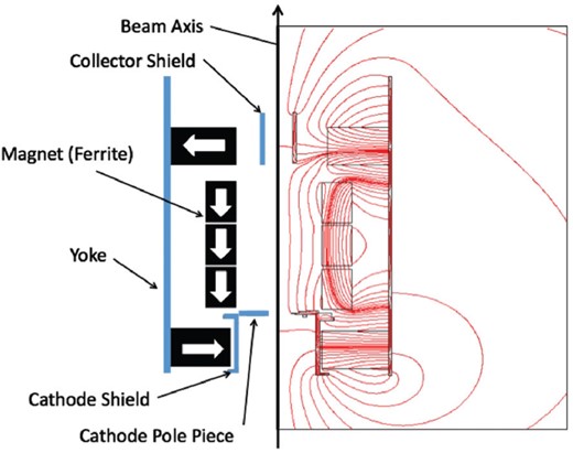
Configuration of magnets (left side of the figure). The calculated field distribution is shown to the right.
3. Design of prototype model
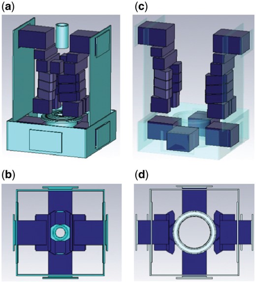
Designed configurations of magnets and iron yoke. (a) Magnets positioned for beam operation. (b) Top view of the location of the magnets illustrated in (a). (c) Magnet positions for klystron installation. All the magnets with two-fold symmetry can evacuate from the central region to make the space to insert the klystron from the top. (d) Top view of the magnets illustrated in (c). The space of the center region is cleared for the insertion of the klystron tube into the focusing alcove.
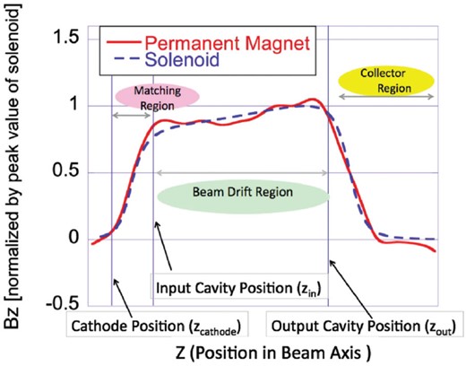
Magnetic field distribution along the beam axis. The electron beam from the cathode is accelerated and matched to the Brillouin flow optics in the matching region and is transported through the beam drift region. It finally goes into the collector region to be damped.
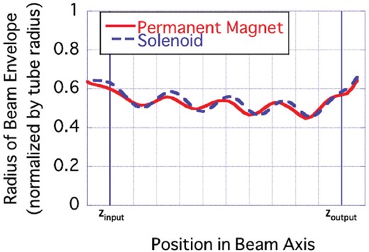
Beam envelopes calculated by 2.5-dimensional simulation with DGUN.
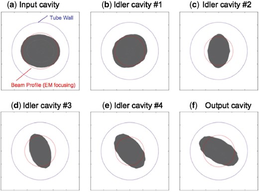
Beam profiles at cavity positions calculated by three-dimensional simulation with CST Particle Studio.
4. Test with prototype magnet
4.1. Fabrication of prototype magnet
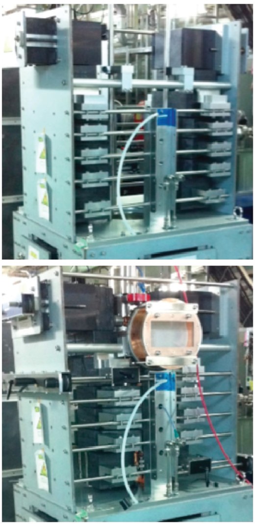
Fabricated prototype magnet. (Top) Klystron insertion mode: magnets are retracted toward the outer sides, making the space to let the cathode assembly part go through, which is the thickest part of the klystron. (Bottom) Klystron operating mode; magnets are moved to the designed position to generate the proper focusing field.
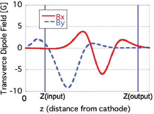
Typical measured transverse (dipole) magnetic fields along the beam axis.
The displacement of the beam center can be estimated with an assumption that electrons follow the magnetic flux lines. The displacement of the flux line at the position can be estimated by integrating the flux line angle () from the beam axis. Using these facts, the beam displacements in the and directions can be derived in a first-order approximation as follows.
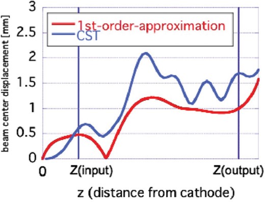
The estimated beam-center displacement due to the transverse magnetic field (see Fig. 7). Both the calculated result of the first-order approximation and the result from a massive simulation with CST Particle Studio are presented.
4.2. Klystron power test
A klystron power test was performed in the summer of 2015 at KEK STF (Superconducting rf Test Facility), where the development of a 40 MeV superconducting test accelerator and ILC-type cryomodules were ongoing at the same time. A 1 MW dummy load was connected. A modulator at the STF building in KEK supplied the power for the klystron, including heater power, cathode high voltage, and modulating anode pulse. A preliminary result of the power test was presented in Ref. [6]. In the initial stage of the experiment, a diode test was carried out. In this test, no RF power was fed to the input cavity and the beam was just transported to the collector. The cathode voltage was set between 45 kV and 67.5 kV, and the modulating anode voltage at beam extraction was 0.26 times the cathode voltage. The measured perveance of the extracted beam was . This value is the same as the result using the solenoid (). Since the perveance is determined only by the gun geometry, it is reasonable. Then, the measured result suggested that an extracted beam condition similar to that with EM focusing could be achieved. During the beam extraction test, the temperature rise of the cooling water for the klystron body was monitored, and no significant temperature rise was detected. These results suggested that the amount of electron loss on the klystron tube body was ignorable and our prototype magnets had sufficient beam transport efficiency.
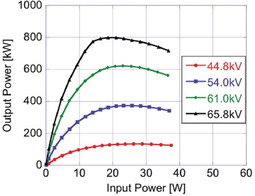
The output RF power of the DRFS klystron with permanent magnet focusing as a function of input RF power at four cathode voltages.
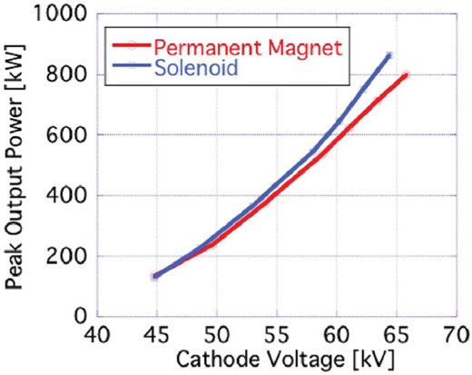
The results of the power test. Output RF power is shown as a function of the cathode voltage with permanent magnet focusing and solenoid focusing.
5. Discussion
5.1. Output power compared with solenoid focusing
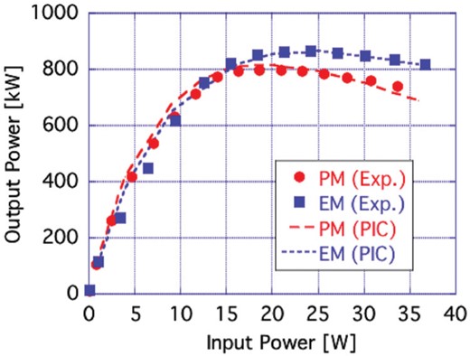
The input–output characteristic both measured in the power test and calculated with PIC (particle-in-cell) simulation.
The main reason for the discrepancy in output power between the PM focusing and the EM focusing is considered to be beam deformation and displacement due to the small multipole field components. Beam deformation and displacement leads to asymmetric distribution of the particles and may cause excitation of higher-order modes in the cavities such as TM110 and TM210 modes. The kick due to the higher-order modes and dipole magnetic field might cause beam loss and decrease output power. However, a significant temperature rise of the tube outer wall was not observed, indicating that there were no beam losses in the klystron tube during the power test. The deformation of the beam decreases the clearance between the beam envelope and the tube wall (including cavity iris), and pushes up the global coupling factors between the beam and the cavities, which represents a coupling factor averaged over all the electrons in the beam (see Appendix).
The calculated value of the global coupling factor focused by the PM without dipole error was about 1% larger than the EM focusing. As the beams propagate through the tube, beams with larger energy modulation would result in larger density modulation and larger RF current of the beam. Since the cavities in the klystron are designed and tuned for a beam focused with EM focusing, an electron beam with a larger beam–cavity coupling factor tends to be longitudinally over-focused at the output cavity. According to the one-dimensional klystron simulation, while a small increase of less than 1.2% relative to the global coupling factor value for the EM focusing leads to an increase of the output power, a larger increase of the global coupling factor causes a decrease in the output power. Therefore, with perturbation on the global coupling factor larger than 1.2%, the maximum bunching efficiency and the induced RF current in the output cavity decrease compared with EM focusing. With PM focusing with a dipole error, the perturbation of the global coupling factor was larger than 2% and expected output power is less than with EM focusing.
To evaluate the effects of the beam displacements and deformations, three-dimensional PIC (particle-in-cell) simulations with CST Particle Studio were also performed. In the simulation, the excited voltages of higher-order modes were less than those of the fundamental mode by two orders of magnitude. In addition, any beam loss in the beam drift region was not observed in the simulations. The simulation results showed the tendency of changing the output power with the PM focusing compared with the EM focusing as predicted from the one-dimensional simulation discussed above. The calculated output power with the EM focusing (case-0) was . This result is consistent with the experimental result. The calculated output power with the PM focusing without dipole field component (case-1; with quadrupole field) was . With the dipole field shown in Fig. 7, the peak output power with the PM focusing (case-2; with both the dipole and the quadrupole field components) was calculated as (the output power was decreased to of that with the EM focusing). These results suggested that the dipole fields in the prototype PM focusing system reduce the output power. In order to evaluate the effect of quadrupole components, we carried out a beam simulation in the EM focusing system on which the dipole component is superposed (case-3; with dipole field). While the system is not a real one, the output power was estimated at . These simulation results can be summarized as follows: either the dipole field or the quadrupole field component slightly enhances the output power, and the existence of both dipole and quadrupole field components reduces the output power. Therefore, it is suggested that the reduction of the output power in case-2 was due to not only the dipole component, but the sum effect of the dipole and quadrupole field components. The reduction of the output power is supposed to be caused by the excess of the beam–cavity coupling due to the beam center displacement and the beam deformation. In Fig. 11, the input–output characteristics both measured in the power test and calculated by the PIC simulations are presented. In the PIC simulations, the induced voltages of idler cavities () were also monitored (see Table 1). The calculated results shows that all the induced voltages with the PM focusing are larger than those with the EM focusing, which indicates that the former case has larger global coupling factors than the latter.
Calculated voltages induced in the idler cavities with 20 W input power.
| Idler cavity # | [kV] | [kV] | [%] |
|---|---|---|---|
| 1 | 19.56 | 19.27 | 101.3 |
| 2 | 6.86 | 6.84 | 100.3 |
| 3 | 20.04 | 19.75 | 101.4 |
| 4 | 34.93 | 33.83 | 103.2 |
| Idler cavity # | [kV] | [kV] | [%] |
|---|---|---|---|
| 1 | 19.56 | 19.27 | 101.3 |
| 2 | 6.86 | 6.84 | 100.3 |
| 3 | 20.04 | 19.75 | 101.4 |
| 4 | 34.93 | 33.83 | 103.2 |
5.2. Suppression of the transverse field
As discussed in the previous subsection, the beam-to-RF power conversion efficiency was supposed to be deteriorated by the transverse multipole magnetic field on the klystron designed for axisymmetric field focusing. After the completion of the allowed experiment time in the busy STF schedule, improvements to the focusing system were studied. To recover the output power, the multipole field components have to be suppressed. The transversal segmentation of the magnets with a higher symmetry would result in fewer multipole components. The magnet configuration with two-fold axial symmetry about the beam axis generates the quadrupole components, which was not supposed to have much effect on the efficiency at the design stage. It should be noted that the construction of a more highly symmetric structure leads to more difficulty in the magnet position alignment and complexity of the mechanical support of the magnets. Considering the above-mentioned situation, and the fabrication and the assembling cost, a transverse field suppressor is favored rather than the modification of the magnet structure in a fancy way.
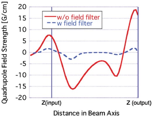
Transverse quadrupole magnetic field calculated with CST EM studio. The transverse field filter reduces the quadrupole field to less than 20% of the field without the filter.
PIC simulation results with the filter showed the improvement of the output power. The calculated output power with the filter-installed PM focusing was . The output power becomes almost the same as that with the EM focusing case. A PIC simulation including the magnet imperfections with the field filter showed no output power reduction. These results indicate that such a filter effectively reduces the transverse multipole components.
6. Conclusion
Klystron beam focusing systems with permanent magnets are well suited to large accelerator facilities such as future linear colliders to enhance their reliability and reduce costs. Even the prototype system with the ferrite magnets for 1.3 GHz, 800 kW klystrons exhibits performance almost the same as with EM focusing. This PM focusing system could not be optimized because of the limited trial and experiment time. To reduce the fabrication costs, anisotropic ferrite was adopted as the magnetic material and the magnets were designed to be pushed in after the klystron tube insertion to the focusing alcove. The movable magnet feature could also be usable for the field tuning process. The technologies adopted in the prototype system can be applied to other klystrons such as the multi-beam klystron for ILC. Furthermore, by mitigating the effects of the transverse magnetic field, the focusing system with permanent magnets can also reduce the power consumption in the accelerator facilities.
Acknowledgements
This work was supported by the Collaborative Research Program of the Institute for Chemical Research, Kyoto University (grant # 2016-10). The authors thank Mr. Y. Okubo at Toshiba Electron Tubes & Devices Co., Ltd. for giving us the klystron data and for the fruitful discussions on the klystron, and thank Dr. H. Hayano at KEK for his continuous encouragement and fruitful comments. The authors also thank Dr. S. Fukuda, Dr. S. Michizono, and Dr. T. Matsumoto at KEK for their support in executing the klystron power test. The experimental results presented in this paper could not have been acquired without their help.
