


Abstract
Emission of muonium (|$\mu ^+e^-$|) atoms from a laser-processed aerogel surface into vacuum was studied for the first time. Laser ablation was used to create hole-like regions with diameter of about 270 |$\mu $|m in a triangular pattern with hole separation in the range of 300–500 |$\mu $|m. The emission probability for the laser-processed aerogel sample is at least eight times higher than for a uniform one.
The muon |$g-2$| is one of the fundamental particle properties for which both theory and experiments can achieve very high precision. It has been known that there is a discrepancy of about 3.5 |$\sigma $| between the best existing measurement from the Brookhaven experiment (E821) [1] and the best theoretical estimates [2,3]. We are preparing a new experiment at J-PARC to measure the |$g-2$| value based on a different approach, namely the use of an ultra-cold muon beam. One of the key steps in the production of the required intense beam is the ion source, in this case positive muons (|$\mu ^{+}$|) with extremely precise momentum. In order to accomplish this goal, we have investigated the creation of neutral muonium atoms (|$\mu ^{+}e^{-}$|, or Mu) with limited spatial extent in vacuum at room-temperature thermal energies and with efficiency as high as several percent from a J-PARC low-energy muon beam. The ultra-cold muon beam for the |$g-2$|/EDM experiment would result from laser ionization of Mu in vacuum and subsequent acceleration of |$\mu ^{+}$|. This paper reports a major step toward our goal via the use of silica aerogel targets with Mu-emitting surfaces that were microstructured with a laser ablation technique.
The new approach to be used in the |$g-2$|/EDM experiment at J-PARC does not need a focusing electric field and thus removes the constraint of “magic” muon momentum (3.094 GeV |$c^{-1}$|) as used in the E821 measurement, so one can use a compact muon storage ring for 300 MeV |$c^{-1}$| muons with a high-precision magnetic field based on magnetic imaging technology, and a compact detection system with particle tracking capability [4]. A statistically competitive measurement requires the production of an ultra-cold muon beam with intensity of the order of 10|$^6$| s|$^{-1}$|. Positive muons of several MeV energy and intensity of order 10|$^8$| s|$^{-1}$| are first stopped or thermalized near the surface of a suitable material. Some of the muons are emitted into the vacuum as thermal muonium with small momentum and energy spread. Laser ionization and acceleration then create an ultra-cold muon beam.
Utilizing a stopping target with high Mu emission rate is essential; we have undertaken systematic investigations of different types and forms of materials. Silica powder has been known to be one of the best materials [5,6], but a major problem with the silica powder is its difficulty in handling, especially in a high-vacuum accelerator environment. In addition, lack of stability of the bulk powder shape and the surface condition has been observed to cause emission variations in long-term measurements such as those required for muon |$g-2$|/EDM. We focus our study on silica aerogel, which has a similar microscopic structure to silica powder, but is rigid and can be conveniently placed at any orientation in vacuum.
We reported our first measurement of muonium emission from silica aerogel [7] performed at the TRIUMF M15 beam line in 2010 and 2011. In the measurement, we successfully observed muonium in vacuum from silica aerogel samples of various densities with yields about 0.3% per stopping muon, for emission followed by decay in a region from 10 to 40 mm from the aerogel surface. This corresponds to a total Mu emission probability of 1.0% for decay in vacuum in a diffusion model interpretation. However, the Mu emission probability was smaller than published values for silica powders [5,6] and hot tungsten [8]; an order-of-magnitude improvement is necessary for silica aerogel to be considered as a viable alternative source for an ultra-cold muon beam.
One main conclusion of Ref. [7] was that the limitation to Mu emission was due to the small scale of Mu diffusion distances compared with the extent of the muon stopping and Mu formation distribution in aerogel. The typical distance between the point of Mu formation to the position of decay of the |$\mu ^{+}$| in its 2.2 |$\mu $|s mean lifetime was at best only about 30 |$\mu $|m in the aerogel material. This is small compared to the extent of the muon stopping distribution of about 2 mm, meaning that only those Mu originating near the flat aerogel surface could escape from it with significant probability; most muonium atoms decayed within the aerogel. We considered methods by which more Mu could be inside the aerogel material at locations closer to its surface.1 Simulations based on a diffusion model showed that the emission rate could be increased substantially by an irregular surface, covered by holes or channels with dimensions of order 100 |$\mu $|m.
The highly uniform silica aerogel was produced by the same methods described in the previous paper [7,9]. We considered and tested several methods to create a non-uniform structure on this uniform aerogel surface. Because the silica aerogel is rather fragile, mechanical treatment of the surface is not considered very promising. It is known that laser light can be used for processing aerogel material [10]. The laser material-processing method for our targets was developed and tested in RIKEN before the actual processing was done commercially.
The indentations or holes were created by ablation with a femtosecond laser with wavelength 800 nm, pulse duration 230 fs, and energy 0.6 mJ/pulse, at a 1 kHz repetition rate. The laser pulse was focused on the surface of the silica aerogel with a spot size of 30 |$\mu $|m. The processing time for each hole was 0.8 s, corresponding to 800 pulses. An aerogel surface area of |$30\times 30$| mm|$^2$| was covered by a triangular pattern of holes with equal spacing of 300, 400, or 500 |$\mu $|m. After ablation, the hole depths were typically 4.5 to 5.0 mm, compared to the total thickness of 7 mm for the 29 mg cm|$^{-3}$| aerogel samples. The diameter of the holes at the surface of the aerogel was about 270 |$\mu $|m, enlarged compared to the laser size by the induced plasma. Surprisingly, the difference in aerogel sample mass measured before and after the ablation procedure was only 5–10% of the expected difference based on hole geometry and aerogel density, perhaps due to densification of aerogel in the vicinity of the holes. Detailed microscopy showed that the holes were not smooth and regular in shape, but were surrounded by microfractures. Figure 1 shows an optical microscope image of the hole pattern, as well as a photo of one of the targets in a holder prior to exposure to muons. Note the bend created in the aerogel sample as a result of contraction after ablation from one side. We expect to be able to reduce or eliminate this curvature by modification of the laser process.
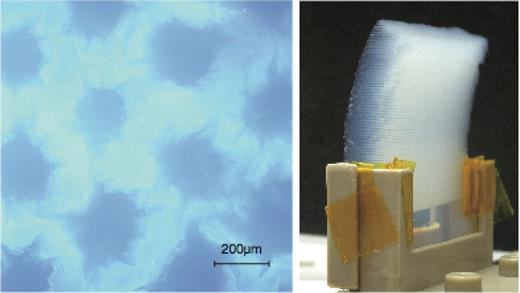
(left) An optical image of an aerogel sample having a triangular hole pattern with equal spacing of 400 |$\mu $|m. (right) Photograph of a laser-ablated aerogel sample installed on a target holder. The muon beam enters the convex surface while muonium is emitted from the ablated (concave) surface.
The identification of muonium emission from aerogel samples with our apparatus has been described in detail elsewhere [7], and is summarized here. The position of a positive muon decaying near the planar target surface can be inferred via an extrapolation of points on the track of the positron emitted in the decay. The positron energy should also be measured in order to select higher-energy particles whose multiple scattering is less severe, thus improving the extrapolation precision. The time of decay, along with the muon arrival time in the target, determines a time interval that is the muon lifetime. When muonium is emitted from the surface of the aerogel sample, this interval includes the time of flight from the target to the point of decay. The time interval and position allow us to infer the component of velocity perpendicular to the surface following emission.
The apparatus, shown in Fig. 2, provides an image of the muon stopping position and the decay time. Coordinates of the positron track were determined in the vertical (|$y$|) and beam (|$z$|) direction by multiwire drift chambers (MWDCs). A pair of plastic scintillators (|$e^{+}$| trigger) determined the decay time and the NaI crystal measured the positron energy. The beam of subsurface muons from the TRIUMF M15 low-energy muon beam line entered the target vacuum system in the |$+z$| direction through collimators and a vacuum isolation window. Muons passed through a 300 |$\mu $|m beam scintillator into the target sample, whose exit surface was reproducibly located at |$z=0$|; there was some ambiguity introduced by the curvature shown in Fig. 1, but not large enough to influence the results presented here. The beam intensity was of the order of |$10^{4}$| s|$^{-1}$|. Thicknesses of the isolation window and the scintillator were minimized so that the lowest practical momentum could be achieved, as this reduces the extent of the muon stopping distribution for a given beam line momentum resolution |$\Delta p/p$|, typically 5% (FWHM). The targets were selected to have approximately equivalent mass per unit area to reduce differences in beam momentum requirements. As a result, the central momentum was typically near 23.0 MeV |$c^{-1}$| to stop half of the beam in a target layer, with only small variations among targets.
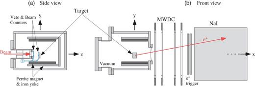
Setup for the muonium imaging measurement at the TRIUMF M15 beamline. The axes of the coordinate system (|$x, y, z$|) follow the right-hand coordinate system as indicated in the figure.
The probability that a muonium atom reaches the surface of the aerogel target layer and is emitted into vacuum depends on the location at which the muonium is formed inside the layer; the nearer the muonium atom is to the surface at the beginning of its motion in the silica aerogel, the more likely it is to be emitted from the surface. Simple planar diffusion models of the motion predict that this probability falls exponentially with initial distance from the surface for a decaying particle. The exponential has a mean distance or planar diffusion length |$l_{d}=(D\tau)^{-\frac {1}{2}}$|, where |$D$| is the diffusion parameter and |$\tau $| is the mean lifetime. In practice, the diffusion length is small compared to both the thickness of the target and the range spread of muons stopping in the target. Thus it is expected that the highest rate of muonium emission into vacuum would be achieved when the stopping density is maximized within the small distance |$l_{d}$| of the surface. This optimization can be accomplished with the muon decay position imaging system; it is used to record the relative rate of muon decays in the target as the mean beam momentum—thus the muon stopping position distribution—is adjusted.
The position resolution of the positron track extrapolation was estimated as |$\sim $|2 mm (RMS) using data taken with a target designed specifically for calibration and background estimation, a silica plate of thickness 100 |$\mu $|m. The time distribution of the positron tracks was analyzed in four |$z$| regions. The first region, defined to include decays both from the target and up to 40 mm into the vacuum following the target, included the entire range (|$-8<z<40$| mm) considered in this analysis. Vacuum regions 1, 2, and 3 were defined as 10 mm-wide ranges of |$z$| starting from 10, 20, and 30 mm respectively from the emitting surface of the target (|$z = 0$|). The time distributions for the flat aerogel and ablated aerogel within these regions are shown in Fig. 3. The time distribution appears mostly exponential for decays of muons or Mu from the entire region. The Mu in vacuum,2 on the other hand, moves across regions 1–3 with a thermal velocity. The time distribution of such Mu is a convolution of the emission time for Mu to escape the aerogel sample and the flight time determined by the velocity distribution, creating the peak structure in the regions 1–3. There are small contributions in regions 1–3 from muon decay events in the target that were subtracted by assuming the exponential functional form in order to estimate the yield of muonium in vacuum.
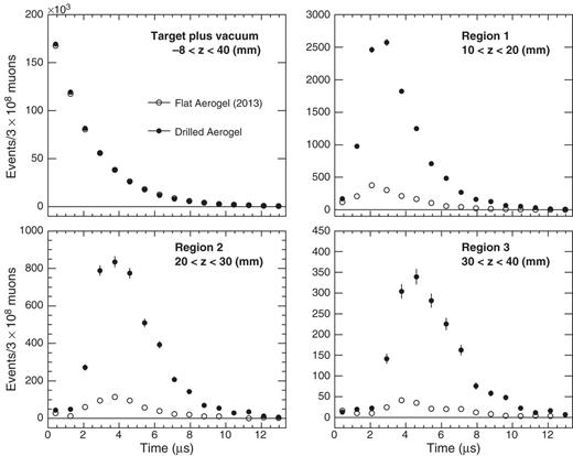
Time distributions of positrons in the entire target region and in each of three vacuum regions, for flat aerogel (open circles) and laser-ablated aerogel with pitch of 300 |$\mu $|m (closed circles). No background has been subtracted.
Table 1 summarizes the Mu yield, after subtraction of the background, summed for regions 1–3. The beam momentum was set to stop about 50% of muons in the sample; the remainder mostly escaped from the target and vacuum regions where their decays were not detected. The quoted uncertainties are statistical only. Most systematic uncertainties are removed by the model-independent yield analysis; those that remain are estimated to be at the level of 4% from the laser-ablated targets, dominated by the effect of curvature of the emitting surface, and about 1% for the flat samples. The Mu yield from the flat sample is about 40% higher than that in Ref. [7]. The densities and geometrical dimensions are nearly identical for both samples. However, they were manufactured by slightly different processes; supercritical ethanol drying at 260 |$^{\circ }$|C was used in Ref. [7], while supercritical carbon dioxide drying at 80 |$^{\circ }$|C was used for the samples in this work. This could lead to the difference in the Mu yield for the slightly different flat samples. An enhancement of Mu in vacuum from the laser-ablated aerogel compared to flat aerogel is evident. The yield is higher when the hole pitch is smaller. The highest yield observed among these targets was the laser-ablated sample with 270 |$\mu $|m diameter and 300 |$\mu $|m pitch. That yield is 3% compared to the total number of muons observed to decay in the combined target and vacuum regions.
Yield of Mu in the vacuum regions 1–3. For all laser-processed samples, the diameter of the structure is 270 |$\mu $|m.
| Sample | Laser-ablated structure (pitch) | Vacuum yield (per |$10^3$| muon stops) |
|---|---|---|
| Flat | none | |$3.72 \pm 0.11$| |
| Flat (Ref. [7]) | none | |$2.74 \pm 0.11$| |
| Laser ablated | 500 |$\mu $|m | |$16.0\pm 0.2$| |
| Laser ablated | 400 |$\mu $|m | |$20.9\pm 0.7$| |
| Laser ablated | 300 |$\mu $|m | |$30.5\pm 0.3$| |
The application of this result to development of a muonium production target in the |$g-2$|/EDM experiment at J-PARC is discussed in the following. The beam momentum and its spread at J-PARC is designed to be 28 MeV |$c^{-1}$| and 5% (RMS), respectively. The projected yield of muonium at J-PARC is estimated as 0.01 per incident muon under the assumption that only a small region near the surface contributes to emission [7]. Taking into account the area of overlap of muonium in vacuum with the ionizing laser, and the ionization efficiency [4], the estimated ultra-slow muon rate is |$0.2\times 10^{6}$| s|$^{-1}$|. This is five times smaller than the design intensity to achieve the final statistical sensitivity of 0.1 ppm on |$g-2$|. Further improvement on the muonium yield is necessary to reach the final sensitivity. Nevertheless, the projected statistical sensitivity with the current muon source is 0.4 ppm for |$g-2$| in |$10^7$| s of data acquisition time with 50% beam polarization, exceeding the precision of the previous measurement [1].
A technology was developed to introduce non-uniform structure (holes) on the surface of silica aerogel samples with laser ablation. Emission of muonium into vacuum increased in all laser-treated samples tested. The emission rate for the ablated aerogel with holes of pitch 300 |$\mu $|m is at least eight times higher than that without the laser treatment.
Acknowledgements
The authors are pleased to acknowledge the support from TRIUMF to provide a stable beam during the experiment. Special thanks go to R. Henderson, R. Openshaw, G. Sheffer, and M. Goyette from the TRIUMF Detector Facility. We also thank D. Arseneau, G. Morris, B. Hitti, R. Abasalti, and D. Vyas of the TRIUMF Materials and Molecular Science Facility. Practical advice and laser equipment given by Yuichi Asakawa of LIGHTEC Inc. has been a great help in the fabrication of laser-ablated aerogel. We are grateful for useful discussion with E. Torikai and her support. Research was supported in part by MEXT KAKENHI Grant Number 2318005 and 2318001 (Japan), NSERC Discovery Grant (Canada), and Center for Korean J-PARC Users No. NRF-2013K1A3A7A06056592 (Korea).
We refer here to the aerogel surface as that determined by the shape of the sample of aerogel. Note that the area of the silica surface in aerogel is typically extremely large, up to 1000 m|$^{2}$| g|$^{-1}$| in some of our samples.
Note that the interpretation of the vacuum decay events as arising from non-neutral forms (|$\mu ^{+}$|) is excluded; a vertical magnetic field of 8 mT was present in all measurements that would cause thermal charged forms to curl back to the target surface via cyclotron motion.
References
Author notes
Present Address: Dept. of Physics, Kyoto University, Kyoto, Japan
Present Address: School of Physics and Astronomy, Queen Mary University of London, Mile End Road, London E1 4NS, UK
