


Abstract
Measuring photosynthesis or primary productivity in biofloc technology production systems is challenging because the biofloc must be maintained in suspension constantly. Photosynthesis can be measured in external incubators designed to keep the biofloc suspended in the biochemical oxygen demand (BOD) bottle, but primary productivity must be measured in the biofloc technology production system culture unit. Therefore, a submersible device is required to keep the biofloc suspended in the BOD bottle. This report details a submersible, air‐powered magnetic stirrer that we designed, fabricated from off‐the‐shelf materials, and tested in biofloc technology production system tanks.
The assemblage of microorganisms suspended in the water column of a biofloc technology (BFT) production system is active in controlling total ammonia nitrogen (TAN) excreted by the intensively fed fish or shrimp being grown (Burford et al. 2003; Hargreaves 2006; Avnimelech 2007; Green 2010). Total ammonia nitrogen is utilized by chemoautotrophic bacteria for the nitrification process, by heterotrophic bacterial biomass production, and by phytoplankton biomass production (Brune et al. 2003; Ebeling et al. 2006). The contribution by phytoplankton to TAN control can be estimated by measuring primary productivity. Primary producers in BFT culture units include phytoplankton (planktonic), as well as algae and cyanobacteria that are associated with biofloc particles (Burford et al. 2003; De Schryver et al. 2008; Ray et al. 2010; Schrader et al. 2011). Water currents generated by continuous aeration of BFT culture units keep biofloc particles suspended and moving throughout the water column. Primary productivity has been studied extensively in aquaculture ponds, but only one study assessed photosynthesis in a BFT production system. In that study, Vinatea et al. (2010) measured photosynthesis in water from a BFT raceway used for marine shrimp culture. They measured water column photosynthesis and respiration weekly by incubating light–dark biochemical oxygen demand (BOD) bottles in the laboratory in an incubator filled with clear water and exposed to artificial lighting, as well as in a greenhouse in an incubator through which water from the BFT raceway circulated continuously.
Primary productivity is measured by incubating light–dark bottles at intervals throughout the photic zone (Eaton et al. 2005). The constant mixing required for maintaining the biofloc suspended in the water column of the BFT production system presents a challenge to measuring primary productivity. The incubator used by Vinatea et al. (2010) contained a rotating wheel to which BOD bottles were affixed. However, this apparatus cannot be used for primary productivity determination within the BFT culture unit. One solution would be to use a submersible magnetic stirrer to maintain the biofloc in suspension inside the BOD bottle. Commercially available submersible magnetic stirrers are expensive and often operate on AC power, and an air‐powered submersible stirrer could not be found. Smith and Smith (1964) described an air‐powered, submersible magnetic stirrer that was fabricated from molded plastic but provided no fabrication or sourcing details.
Inspired by Smith and Smith (1964), we report on an air‐powered, submersible, magnetic stirrer that we designed, fabricated, and tested for use in measuring photosynthesis in BFT culture tanks.
METHODS
Magnetic stirrer fabrication.—The magnetic stirrer is constructed as follows. Use a chop saw fitted with a fine‐tooth blade to cut a 15‐mm (0.59‐in) wide section from a piece of schedule‐40 polyvinyl chloride (PVC) pipe (102‐mm [4‐in] inside diameter [ID]) to make the stirrer body. (Note that appropriate personal protective equipment and safety procedures should be used during all stages of fabrication.) Mark the locations on the pipe section edge for the air inlet and outlet hose barbs by measuring from the outside edge of the pipe 14 mm (0.55 in) along the diameter and then 37 mm (1.46 in) perpendicular to each side of the diameter. Secure the pipe section in a vise on a drill press platform such that the diameter is perpendicular to the platform and the air inlet marks are visible. Drill a hole at each mark using a 8.3‐mm (21/64 in) drill bit and then tap threads in each hole using a taper pipe tap (1/8‐in 27 National Pipe Thread [NPT]). Screw a threaded × barbed nylon connector (1/8‐in NPT × 3/8‐in barb) into each hole and trim the exposed connector base flush to the interior pipe wall.
The impeller diameter is 98 mm (3.86 in) and is cut from a 12.7‐mm (0.5 in) thick high‐density polyethylene (HDPE) sheet using a rotary cutter (MultiPro, Dremel, Racine, Wisconsin) fitted with a multipurpose cutting bit (no. 561, Dremel) and using the circle cutter and straight edge guide (no. 678–01, Dremel). Insert a screw through the center hole of the impeller and screw to a block of wood; clamp the wood block to a drill press platform. Place the center point of a 19‐mm (0.75 in) Forstner drill bit at the edge of the impeller and drill through. Then rotate the impeller clockwise and repeat the drilling process a total of 12 times, leaving about a 3‐mm (0.12 in) gap between borings. Next, measure 12.7 mm (0.5 in) along the diameter on either side of the center hole, mark, and use a 12.7‐mm (0.5 in) drill bit to drill a 7.4‐mm (0.29 in) deep hole. Place one drop of medium‐set PVC cement in the bottom of each hole and insert a 12.7‐mm‐diameter × 6.4‐mm (0.5 × 0.25 in) neodymium disk magnet (grade N42, K&J Magnetics, Jamison, Pennsylvania), ensuring that the north pole faces up in one magnet and the south pole faces up in the other magnet. Next, use a 4.8‐mm (3/16 in) drill bit to drill a 2.5‐mm (0.1 in) deep hole in the center of each side of the impeller. Place one drop of medium‐set PVC cement in each hole and insert a stainless steel ball bearing (diameter, 4.8 mm [3/16 in]). Lastly, use the Forstner bit to drill a hole centered 15 mm (0.6 in) above and below each magnet in order to lighten the impeller.
Use a 114.3‐mm (4.5 in) diameter bimetal hole saw with the center drill bit removed to cut the stirrer top and bottom plates from a 3.2‐mm (1/8 in) thick PVC sheet. In the center of one side of each plate bore a hole for the ball bearing 1.6 mm (1/16 in) deep using a 4.8‐mm (3/16 in) drill bit. Carefully roughen the gluing surface (the outer 7‐mm wide ring) on each of the top and bottom plates. Dispense a thin bead of medium‐set PVC cement around the outer edge of the bottom plate and glue to the stirrer body. Allow the cement to set, insert the impeller, and glue the top plate to the stirrer body; exercise care to avoid introduction of excess PVC cement into the stirrer interior. The partially assembled stirrer is shown in Figure 1. Apply even pressure around the circumference of the top plate to ensure good bonding. Dip the completed stirrer up to the base of the hose barbs into a multipurpose rubber coating (Plasti Dip, Plasti Dip International, Blaine, Minnesota) to ensure water tightness; allow the first coat to dry before applying a second coat.
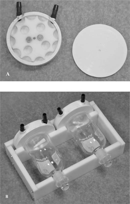
(A) The internal components of a partially assembled, air‐powered, magnetic stirrer; refer to the text for fabrication details. (B) The stirrer–BOD bottle cradle with BOD bottles mounted.
Stirrer–BOD bottle cradle fabrication.—The cradle supports one light and one dark BOD bottle and two stirrers, and is constructed of 12.7‐mm (0.5 in) thick HDPE as follows. Cut two 25 × 13‐cm (9.8 × 5.1 in) rectangles from a HDPE sheet. Draw a line that bisects the length and the width. On either side of the line bisecting the length, measure 6.4 cm (2.5 in) along the line bisecting the width and place a mark. Use a 76.2‐mm‐diameter (3 in) bimetal hole saw to cut holes at each mark on one rectangle and a 38.1‐mm (1.5 in) bimetal hole saw to cut holes at each mark on the second rectangle. Cut each rectangle in half along the line that bisects the width. The piece with the small holes is the front of the cradle and the piece with the large holes is the back. The sides (14.7×6 cm [5.8×2.4 in]) and back (27.4×6 cm [10.8×2.4 in]) of the cradle are cut from the HDPE sheet. The sides are attached to the front and back cradle pieces using 31.8‐mm (1.25 in) number 8 hex head screws. Measure 7 mm (0.28 in) and 12.0 cm (4.7 in) from one end of each side piece and place a mark. Drill a guide hole for the screw 1 cm (0.4 in) from the top and bottom edges at each mark using a 2.4‐mm (3/32 in) drill bit. Drill corresponding guide holes for each screw into the ends of the cradle front and back pieces. Measure 6 mm (0.24 in) from each end of the back piece and drill guide holes as above. Additionally, drill one guide hole in the center of the back piece for a 44.5‐mm (1.75 in) number 8 hex‐head screw used to tighten the back piece to secure the stirrers in place. The assembled stirrer–BOD bottle cradle is shown in Figure 1.
Two 12.7‐mm‐diameter (0.5 in) steel threaded rods attached to the sides of the cradle are used to position the cradle vertically in the water column. Use a wire welder to weld two 9.5‐mm (3/8 in) one‐hole conduit clamps to one end of each rod such that the clamp holes align with the screws used to fasten the side to the back piece of the cradle and use these screws to attach the rods to the cradle.
Photosynthesis determinations.—The stirrers were validated for photosynthesis determinations in BFT tanks described by Green (2010) and stocked with channel catfish Ictalurus punctatus in a study to evaluate stocking rate at the U.S. Department of Agriculture, Agricultural Research Service Harry K. Dupree Stuttgart National Aquaculture Research Center. Secchi disk visibility (SDV) was measured in each tank 30–60 min before initiating incubation and the photic zone was estimated as twice the SDV (Boyd 1979). Incubation depth was 5 cm for the first three dates and 1 cm for the last date. A length of 5.1×10.2‐cm (2×4 in) lumber with 19.1‐mm (0.75 in) holes drilled to accommodate the threaded rods for each of two cradles was placed across the width of the BFT tank and incubation depth was set by adjusting the position of the hex nut on the threaded rod.
Water samples were collected (1100–1400 hours) from each BFT tank each time photosynthesis was measured. Samples were analyzed for settleable solids (Eaton et al. 2005) and chlorophyll a, which was extracted in 2:1 chloroform : methanol from phytoplankton previously filtered from water samples by using a glass fiber filter with 0.45 μm pore size, and the chlorophyll a concentration in the extract was determined by spectroscopy (Lloyd and Tucker 1988).
Photosynthesis was measured according to the oxygen method described by Eaton et al. (2005) in 3–6 BFT tanks per date by the light–dark bottle method on 9 June and 8, 15, and 28 July 2011. Tanks were selected on each date to represent as wide a range as possible of chlorophyll a concentrations (and presumably photosynthesis); consequently, not all stocking rate treatments were represented on each date, which precluded statistical comparison. On each date, two cradles were used in each tank: stirrers were active on one cradle and inactive on the other. Two clear and two opaque 300‐mL BOD bottles were filled by siphon hose with the corresponding BFT tank water; each bottle was allowed to overflow for approximately three bottle volumes. An octagonal 8×25‐mm (5/16×1 in) magnetic stir bar was inserted into each bottle. Dissolved oxygen (DO) in each bottle was measured immediately after the bottles were filled using a model 5000 DO meter equipped with a model 5010 polarographic BOD probe (Yellow Springs Instruments, Yellow Springs, Ohio), bottle stoppers were inserted, stopper caps placed on opaque bottles, and one clear and one opaque bottle were placed in each BOD bottle per stirrer cradle set at the incubation depth in BFT tanks. Duration of incubation varied from 43 to 86 min among dates and each was selected to ensure that excessive oxygen production or consumption did not occur. Incubation duration among bottles on any given date did not vary more than 7 min. The stirrer was activated with compressed air (103.4–137.9 kPa [15–20 psi]) for approximately 10 s at 3–5‐min intervals during incubation to achieve a moderate stirring speed. Final DO concentration was measured immediately in each bottle at the end of the incubation period. Photosynthesis (mg O2/L) was calculated as follows:
Photosynthetically active solar radiation flux density data for each incubation period and solar day were obtained from our on‐site weather station and were used to adjust photosynthesis to daily (24 h) values, which were divided by 24 to obtain hourly values.
RESULTS AND DISCUSSION
Secchi disk visibility averaged 8 cm for the first three sample dates and 5 cm for the last sample date (Table 1). Thus, the selected incubation depths encompassed a major portion of the photic zone. Mean settleable solids and chlorophyll a concentration averaged 41 mL/L and 866.1 mg/m3, respectively (Table 1), and are consistent with values reported for channel catfish and tilapia Oreochromis mossambicus in BFT culture units (Avnimelech 2007; Green 2010; Schrader et al. 2011). It is important that the biofloc inside the BOD bottle remain suspended to ensure accurate measurement of photosynthesis. Without stirring, the biofloc particles settle out rapidly inside the BOD bottle and limited sunlight penetration into the settled biofloc results in reduced photosynthesis.
Secchi disk visibility (SDV), net photosynthesis (NP), respiration (Resp), gross photosynthesis (GP), chlorophyll a (Chl a), and settleable solids (SS) measured in biofloc technology production tanks stocked with channel catfish. The NP, Resp, and GP (all as mg O2·L−1·h−1) were measured in light–dark biochemical oxygen demand bottles that were stirred or not stirred during incubation. Incubation depth was 5 cm except on 28 July 2011 when depth was 1 cm.
| NP | Resp | GP | ||||||||
| SDV | Chl a | SS | ||||||||
| Date | Tank | (cm) | Stirred | Not stirred | Stirred | Not stirred | Stirred | Not stirred | (mg/m3) | (mL/L) |
| 9 June | 6 | 9 | 0.79 | 0.19 | 1.70 | 1.44 | 2.49 | 1.63 | 782.7 | 70 |
| 9 June | 7 | 10 | 0.26 | 0.30 | 1.27 | 1.12 | 1.52 | 1.43 | 917.1 | 30 |
| 9 June | 8 | 10 | 0.52 | 0.18 | 1.14 | 1.09 | 1.66 | 1.27 | 1,700.2 | 14 |
| 8 July | 2 | 7 | −0.52 | −0.56 | 1.49 | 1.15 | 0.97 | 0.59 | 384.0 | 50 |
| 8 July | 3 | 8 | −0.36 | −0.35 | 1.45 | 1.15 | 1.09 | 0.80 | 496.9 | 24 |
| 8 July | 4 | 7 | −0.40 | −0.31 | 1.67 | 0.98 | 1.27 | 0.67 | 824.0 | 35 |
| 15 July | 4 | 5 | −1.24 | −0.77 | 2.36 | 1.29 | 1.12 | 0.53 | 1,070.1 | 36 |
| 15 July | 5 | 6 | −0.89 | −0.57 | 1.66 | 1.09 | 0.78 | 0.51 | 1,175.1 | 45 |
| 15 July | 6 | 7 | −0.66 | −0.44 | 2.03 | 1.10 | 1.36 | 0.67 | 904.7 | 37 |
| 28 July | 4 | 5 | −0.70 | −0.44 | 2.28 | 1.26 | 1.58 | 0.81 | 882.8 | 55 |
| 28 July | 5 | 5 | −1.61 | −0.91 | 3.04 | 1.46 | 1.43 | 0.56 | 585.8 | 60 |
| 28 July | 6 | 5 | −0.21 | −0.43 | 1.37 | 1.36 | 1.17 | 0.93 | 622.9 | 50 |
| 28 July | 7 | 5 | 0.29 | 0.05 | 2.28 | 1.24 | 2.57 | 1.29 | 1,076.2 | 55 |
| 28 July | 8 | 5 | −0.35 | −0.19 | 2.03 | 1.23 | 1.68 | 1.04 | 569.5 | 45 |
| 28 July | 9 | 6 | −0.01 | −0.26 | 2.03 | 1.22 | 2.01 | 0.96 | 540.0 | 31 |
| Grand mean | 7 | −0.32 | −0.28 | 1.77 | 1.19 | 1.46 | 0.91 | 866.1 | 41 | |
| (SE) | (1) | (0.30) | (0.18) | (0.19) | (0.04) | (0.21) | (0.19) | (134.6) | (3) | |
Stirring affected photosynthesis measurements in BOD bottles (Table 1). Tanks were autotrophic (positive net photosynthesis) on the first sample date and heterotrophic (negative net photosynthesis) on the remaining sample dates. Net photosynthesis (NP) was underestimated by 41.2% (SE, 51.3) in unstirred compared with stirred BOD bottles when tanks were autotrophic and by 20.8% (SE, 8.6) when tanks were heterotrophic. Overall, NP was underestimated by 25.9% (SE, 7.9) when BOD bottles were not stirred during incubation. Respiration was 10.4% (SE, 5.3) and 35.7% (SE, 3.9) lower in unstirred bottles under autotrophic and heterotrophic conditions, respectively; across all dates, respiration averaged 29.4% (SE, 6.9) lower in unstirred bottles. Gross photosynthesis (GP) also was underestimated in unstirred bottles and was 21.5% (SE, 14.1) and 42.9% (SE, 2.6) lower when tanks were autotrophic and heterotrophic, respectively. For all sample dates, GP was underestimated by 37.5% (SE, 5.7) when the BOD bottles were not stirred during incubation. The differences observed between autotrophic and heterotrophic conditions reflected changes in the nature of the biofloc. Tank water was green in color, chlorophyll a concentration averaged 1,133.3 mg/m3, and settleable solids averaged 38 mL/L under autotrophy. By early July, tanks, with one exception on one date, had transitioned to heterotrophy and water was brown in color, chlorophyll a concentration averaged 777.0 mg/m3, and settleable solids averaged 42 mL/L. A similar transition was reported for a raceway used for BFT culture of Pacific white shrimp Litopenaeus vannamei when after 6 weeks of culture the system transitioned from autotrophy to heterotrophy (Vinatea et al. 2010).
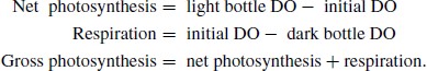
Continuous aeration of the BFT tanks maintained DO concentrations and kept the biofloc suspended and moving throughout the water column at all times. Stirring the BOD bottles briefly at regular intervals throughout the incubation period acted to simulate the turbulent conditions experienced by the biofloc in the open tank (Figure 2). We arrived at this stirring protocol after observing in preliminary work that continuous stirring of the BOD bottles tended to cause the biofloc to concentrate in the center of the bottle, particularly when algae were abundant (green water phase).
![Light and dark BOD bottles deployed on the stirrer–BOD bottle cradle in the biofloc technology production system tank showing the biofloc suspended inside the BOD bottle. [Figure available in color online.]](https://oup.silverchair-cdn.com/oup/backfile/Content_public/Journal/naja/74/3/10.1080_15222055.2012.676018/3/m_naaq0347-fig-0002-m.jpeg?Expires=1750487199&Signature=tt47hr1ZevukU6vA3Wp~gsDGk27kT94qPHAmfNe9I45ZqbhCFfS03MVSdtrCZw9bw5ESgZGIWlBlyUbE-mJ2ib~rKz7iJEhyECmgrvOOFuRRyzM0kH7z6dCzMGXpA5po0J9Ug~2nuZTl2-e40SpF-Dz8DZa97fO1l3FMtAPVFE1qj88e~iTkqZ03SA7bKic2C1rkkRQHFUvarhkQnlrB5ex3Z5SEp811AeClYQZbJqeS0F9MJ-VmVCQlqsiKJFqXhH1GdX89tLFcc~EJMyPa-y~bJNXOChnklI9sB7KhjYIm6R1fnRX8t-Jws0Nr7drQO55ZjiLkmMKEmurRN-2yjw__&Key-Pair-Id=APKAIE5G5CRDK6RD3PGA)
Light and dark BOD bottles deployed on the stirrer–BOD bottle cradle in the biofloc technology production system tank showing the biofloc suspended inside the BOD bottle. [Figure available in color online.]
The described stirrer and cradle proved functional and easy to use. Both designs are scalable and modification may improve functionality. The stirrer could be made smaller, which may lower the air pressure required for operation. For example, the 102‐mm (4 in) or a 76‐mm‐ID (3 in) stirrer could be made thinner by using 6.4‐mm‐thick (0.25 in) HDPE for the impeller and drilling additional holes above and below the magnets to reduce the impeller weight. Thinner magnets and smaller hose barbs also would be required. The cradle could be expanded to accommodate four BOD bottles, thereby allowing duplicate measurements at each depth.
We used off‐the‐shelf materials to fabricate this air‐powered magnetic stirrer that can be operated fully submerged in water in either a vertical or horizontal orientation. Combined with the cradle, BOD bottles can be suspended horizontally in the BFT production system water column at a single depth for photosynthesis measurement or at depths throughout the photic zone for primary productivity measurement.
ACKNOWLEDGMENTS
We thank Rebecca Jacobs for taking the photos for Figure 1. This study was funded by the U.S. Department of Agriculture (USDA), Agricultural Research Service under project number 6225–31630–006–00D. Mention of trade names or commercial products in this article is solely for the purpose of providing specific information and does not imply recommendation or endorsement by the USDA. The USDA is an equal opportunity provider and employer.
