


ABSTRACT
The Antarctic Plateau is considered to be the best ground-based astronomical site on Earth. Compared with other middle latitude observatories, the telescopes located in Antarctica have unique advantages in seeing a large fraction of clear nights, continuous observing window in the polar night, and so on. China has operated several generations of telescopes in Antarctica, but has not yet achieved multicolour simultaneous observation with tracking. Multi-band Survey Telescope (MST) is the first multicolour simultaneous survey telescope in Antarctica. It adopts a Newtonian telescope structure which is different from other Antarctic telescopes and is matched with a new alignment scheme suitable for the harsh environment of Antarctica. In addition, MST is equipped with a defrosting indium tin oxide (ITO) window and a high-precision equatorial mount. This paper introduces the optical design, mechanical structure, and analysis of the actual operation of MST in Antarctica. Since March 2022, MST has been carrying out the observation normally in Zhongshan Station, and the operation of MST has provided a new experience for the follow-up design and installation of Antarctic telescopes. We plan to further optimize the design and manufacture of MST, and develop it as a standard model of small-aperture Antarctic telescopes for space debris observations and time-domain surveys.
1 INTRODUCTION
Ground-based telescopes are inevitably affected by atmospheric seeing (Dierickx 1992). Nevertheless, it is feasible to observe the transit of red dwarfs with the atmosphere scintillation from Earth (Henry et al. 2006; Charbonneau et al. 2009; Gillon et al. 2016; Gillon et al. 2017). However, the detection efficiency of transit photometry with ground-based telescopes is limited by the diurnal cycle of low latitudes – particularly for planets with orbital periods of tens of days (Brown 2003). Dome A in Antarctica has unparalleled advantages regarding the two aforementioned aspects. First, it experiences approximately 5 months of continuous winter darkness, allowing continuous transit observation (Zou et al. 2010). Second, it has recorded a seeing of 0.13 arcsec at an 8-m height at night (Ma et al. 2020). In addition, Dome A has a dark sky background and low cloud fractions. The median thickness of the turbulent boundary layer, above which excellent seeing is obtained, is only 13.9 m in winter, making it an excellent transit observation site (Bonner et al. 2010; Zou et al. 2010). Moreover, according to previous data analysis, Dome A is an excellent place for monitoring space debris in the near-Earth area (Li et al. 2019).
China has supported the development of Antarctic astronomy – particularly Dome A for more than 10 years. The Chinese Small Telescope Array (CSTAR) was the first-generation wide-field telescope at Dome A; it had a 20 deg2 field of view (FOV) with four identical 145-mm entrance pupil telescopes (Yuan et al. 2008). CSTAR was deployed in Antarctica in 2008 and operated continuously for 4 years, obtaining excellent results in variable star detection and atmosphere extinction measurements (Zhou et al. 2010; Wang et al. 2014a, b). The three Antarctic Survey Telescopes (AST3) are second-generation telescopes, each with a 500-mm entrance pupil and an 8.5 deg2 FOV. AST-1 and AST-2 were mounted at Dome A in 2012 and 2015, respectively. They were primarily used for supernovae surveys and exoplanet searches (Yuan & Su 2012). Additionally, the Antarctic Bright Star Survey Telescope (BSST) (Zhongshan Station, Antarctica) has a 300-mm aperture and a 4.8° FOV. It was used to search for bright stars in March 2016 (Liu et al. 2018; Li, Lu & Yuan 2015; Tian et al. 2016).
Several excellent wide-field telescopes, including CSTAR and AST3, have been deployed in Antarctica, but there is still no telescope capable of simultaneous tracking and polychromatic photometry. Multicolour simultaneous photometry is important for the study of variable stars, extrasolar planets, and clusters. However, the polychromatic photometry of AST3 and BSST requires switching filters, and the multicolour simultaneous CSTAR was fixed in position, looking at the South Celestial Pole. We aimed to deploy the first telescope capable of simultaneous tracking and polychromatic photometry in Antarctica. Herein, the Multi-band Survey Telescope (MST) is proposed with the above considerations. It consists of four identical Newtonian telescopes with an aperture of 150 mm, and the two tubes of the MST have motorized filter wheels; thus, it is possible to observe three bands simultaneously. There is an additional tube for back-up. A significant difference between the MST and CSTAR is that the MST has a high-precision equatorial mount; thus, it can realize the task of sky survey and tracking. It has wider application prospects and will play a larger role in exoplanet search, astrometry, etc. The MST was installed successfully at Zhongshan Station in Antarctica in March 2022 and has been used for observation missions normally since then.
In this article, we will introduce the design of MST and evaluate its status and capabilities. The second chapter introduces the design of the MST, the third chapter presents an analysis of the performance of the MST in Antarctica, and the fourth chapter summarizes the MST project.
2 INSTRUMENT
2.1 Design considerations
The Antarctic Plateau has proven to be the best astronomical site on Earth (Lawrence et al. 2004; Ma et al. 2020). However, Antarctica’s low temperature and low-pressure environment pose a challenge to the development of polar observation telescopes. Compared with ordinary telescopes at mid-latitudes, the MST has the following significantly different use environments.
The use temperature is between −10° C and −60° C, and the average temperature in the laboratory is 20° C, which is close to the temperature difference of approximately 100° C; thus, the mirror and mechanical structure are easily deformed.
The climate of the Antarctic inland station is dry, but there is a small amount of water vapour in the air. If the air temperature is below the temperature of the optics, the saturated water vapour in the air is condensed on the window, forming a layer of frost, and there are problems such as snow blowing and attachment, which limit the light-collecting ability of the telescope.
When the metal transmission parts of the equatorial frame of the telescope are exposed to snow blowing or saturated water vapour condensation frost, problems such as blocking and jamming of the transmission chain can occur.
Therefore, the design of the MST is mainly based on the following considerations:
To achieve multi-band simultaneous observation and deal with the possible adverse effects of the harsh environment, we draw lessons from the successful experience of CSTAR: MST is also equipped with four tubes simultaneously. Two of the four identical tubes are equipped with automatic switching filters, and the other two tubes can make full-band observations and serve as back-ups for the telescope. The same structural design is adopted so that the modules can be disassembled and installed with each other, ensuring the normal operation of the telescope to the maximum extent.
Factors such as long-time bumpy transportation, unattended Antarctic regions, difficult on-site installation, and the harsh environment require that the tolerance of the optical system is relaxed to the greatest extent possible, the mechanical structure is easy to install, and the alignment scheme is simple and reliable. Therefore, in addition to relaxing the tolerances to the greatest extent possible, we employ a modular design for the telescope tube and the mount, using dovetail grooves for easy installation. Additionally, the MST uses the latest portable alignment scheme for the first time, which facilitates the installation of the telescope in a harsh polar environment, the details of which are given in section 2.5, and an analysis indicates that this scheme is feasible.
To deal with problems such as Antarctica’s extremely low temperature and snow, we used a window sealed and coated with indium tin oxide (ITO). This part is referred to in the fourth section of the article. For the mechanical structure, we adopted a planetary gear-reducer transmission structure, avoided in the process of telescope observations of unattended, telescope gear meshing tooth often because of snow, or supersaturating water and frost could cause the telescope’s transmission mechanism to stall. We also provided the telescope with a simple and reliable dome to further improve its adaptability to harsh environments.
2.2 Optical design
The optical design of the MST is based on the Newtonian telescope. It includes a defrost window, a primary mirror with an F-number of 3.5, and three correction lenses. The design indices of the optical system are as follows:
Aperture: 150 mm and the obscuration ratio is 28 per cent.
F/number: 2.8.
Optical FOV: 6.08° diameter for circular field following view (4.3° × 4.3° for the square FOV).
Pixel scale: 1.84 arcsec/3.76 μm.
Image quality: 80 per cent energy concentration, diameter of less than 17.5 μm.
Observation wavelength: 400–700 nm.
The optical layout of the MST is illustrated in Fig. 1, and the optical parameters are presented in Table 1.
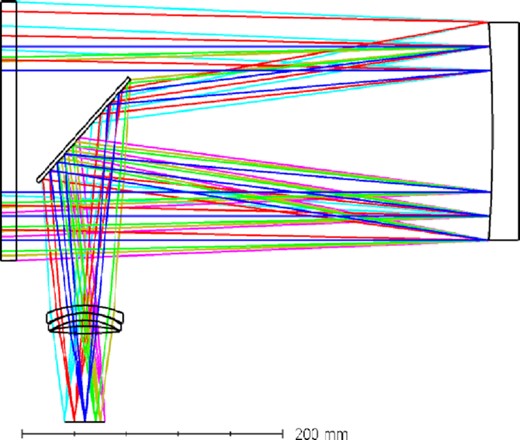
Optical layout of the MST.
Optical configuration of the MST.
| Optical element | Radius (mm) | Conic coefficient | Thickness (mm) | Diameter (mm) | Glass |
|---|---|---|---|---|---|
| Defrost window | Infinity | – | 20 | 150 | Fused silica |
| Infinity | – | 355 | – | – | |
| Primary mirror | −1050 | −2.1 | −312.7 | 150 | – |
| Fold mirror | Infinity | – | 119.25 | – | – |
| Lens 1 | 82.5 | – | 5 | 27 | K9 |
| 60 | – | 0.1 | – | – | |
| Lens 2 | 54 | – | 5 | 26 | H-BAK7 |
| 55 | – | 4 | – | – | |
| Lens 3 | 131 | – | 5 | 25 | K9 |
| −273 | – | 60 | – | – |
Similar to the previous Antarctic telescopes, we installed defrost windows on the MST at the front end of the lens barrel. The defrost window is a piece of fused silica glass coated with an ITO film, which can prevent the accumulation of frost and snow through heat produced by energizing the electrodes at both ends of the loading window.
The optical spot diagram and the diffraction-encircled energy layout of the MST are shown in Figs. 2 and 3, respectively. The MST has a relatively uniform FOV. Its root-mean-square (RMS) radius is 6.5 |$\mu$|m at the maximum FOV of 4.3°. Furthermore, the diameter of the 80 per cent encircled energy (80 per cent EE) is <17.4 μm (8.5 arcsec).
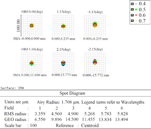
Spot diagram of the MST. The RMS radius at the maximum FOV of 4.3° is 5.8 μm, and the band used for calculation is the visible-light range of 0.4–0.7 μm.
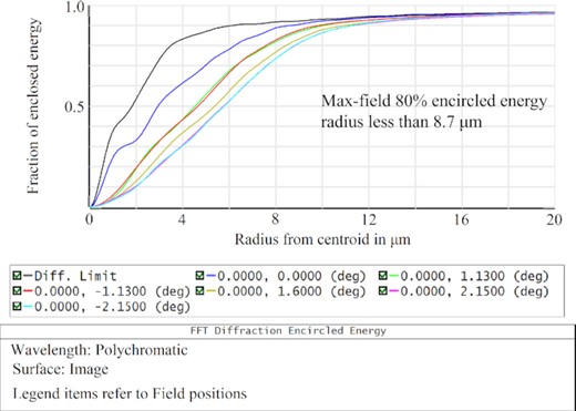
Diffraction-encircled energy of the system. The ordinate indicates the normalized energy measure and the abscissa indicates the radius of the entrant energy. In the worst case of the maximum FOV, 80 per cent of the entrant energy radius of the MST is <8.7 μm.
Additionally, the MST has a focusing structure on the correction-lens group. This can compensate for the defocusing caused by low temperatures and transportation. Additionally, it can compensate for the optical path difference caused by switching between filters, or even using no filter, using a motorized filter wheel. Two of the four lens barrels are provided with motorized filter wheels, each of which is equipped with four filters – L (light, open band), R, G, and B, covering the visible-light band of 400–680 nm. Also,And each motorized filter wheel also reserves a position for observation or subsequent installation of other filters.
Error budget analysis is a necessary task for an optical system. We used the 80 per cent EE radius as the evaluation standard to perform a Monte Carlo analysis 500 times on the MST in four fields (0°, 2.3°, 3.2°, and 4.3°). The tolerance distribution is presented in Table 2, and the results are shown in Fig. 4. The results indicated that the 80 per cent EE diameter at the center-field under 90 per cent probability was approximately 14 |$\mu$|m (7 arcsec). Furthermore, the 80 per cent EE diameter of the MST, under a 90 per cent probability, was smaller than 23 |$\mu$|m (10.8 arcsec) for the maximum FOV, and the maximal 80 per cent EE diameter of MST was approximately 25 μm (12.3 arcsec) at the maximum FOV under a 99 per cent probability. These two values are very close and this analysis confirmed that both the manufacturing process and the alignment are feasible.

Results for the error budget. Even with the maximal FOV, 99 per cent of the 80 per cent EE diameters are less than 25 μm (12.3 arcsec).
Tolerance distribution.
| Manufacturing error budget | ||||
|---|---|---|---|---|
| Items | Thickness (mm) | Radius (mm) | Conic | Nominal (mm) |
| Primary mirror | – | ±0.6 | ±0.0001 | (−1050, −2.1) |
| Fold mirror | – | - | - | – |
| Lens | ±0.03 | - | - | (5, 5, 5) |
| Alignment error budget | ||||
| DOF | Decentre (mm) | Tilt | Position (mm) | |
| Primary mirror | - | - | - | |
| Fold mirror | ±0.06 | ±3 arcmin (0.05°) | ±0.4 | |
| Corrector | ±0.1 | ±3.6 arcmin (0.06°) | ±0.4 | |
| Lens space | - | - | ±0.05 | |
2.3 Heated window
Although the Antarctic is dry and rainless, there is a small amount of water vapour in the air. When the air flows over the surface below its freezing temperature, the water vapour in the air is condensed and adheres to the solid surface, forming a layer of frost. If this is not handled in time, it will lead to the failure of the telescope mirror and hinder the observation. However, improper defrosting methods significantly affect the mirror seeing. The method of defrosting by heating the ITO conductive film has the characteristics of no contact with a mirror, high transmittance, uniform heating, and mature technology. The MST adopts this scheme. Four visible-light telescopes are equipped with glass windows coated with an ITO film, as shown in Fig. 5, which are heated by two copper electrodes on the sides of the windows. The window heating is powered by a 36-V power supply, and each cable can heat two windows simultaneously. The resistance of the single lens barrel is 42 Ω and two windows are connected in parallel for heating. The measured resistance is 21 Ω and the window power supply voltage is 36 V. When the heating power is controlled, the average temperature of the window surface is approximately 2° C higher than the ambient temperature. Practice has shown that when the temperature difference is controlled at approximately 2° C, the defrosting effect can be achieved, and the air convection caused by the temperature difference can be significantly reduced, ensuring the imaging quality (Qing-chen & Xiao-yan 2019).
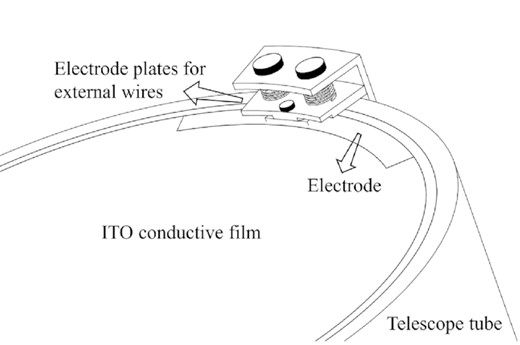
Window sealing with ITO conductive film, which ensures the connection of the heating circuit using a tablet.
2.4 Telescope mount
The telescope uses a high-precision equatorial frame, as shown in Fig. 6. The standard maximum steering speed of the mount is 12° per second, the maximum speed is 60° per second, and the maximum load is 200 kg. The design principle for the tracking accuracy of the telescope is that the RMS value (10 min) is <0.5 arcsec. With regard to the mechanical structure, we adopt the structure of planetary gear-reducer transmission to avoid blocking of the telescope transmission mechanism due to snow blowing or supersaturated water vapour condensation frost in the telescope gear meshing slot during unattended observation.
To test the reliability of the design and facilitate a comparison of the mount’s performance in Nanjing and Antarctica, we trial-installed the MST in Nanjing (30° C) and tested the tracking accuracy of the mechanical structure. According to this test, the stellar tracking accuracy was 0.14 arcsec, of which RA RMS = 0.103 arcsec and DEC RMS = 0.09 arcsec.
2.5 Telescope tube and alignment
The difficulties of the Antarctic installation conditions were considered in designing the telescope. Hence, loose tolerances were assigned, and a focusing mechanism was provided for easy alignment. Recent domestic imaging indicated that the telescope could achieve diffraction limits with proper alignment, as shown in Fig. 7.
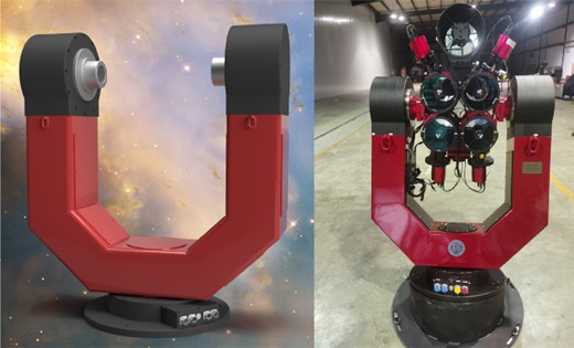
Mount of the MST. At the top is an 8-inch RC telescope for short-wave infrared (SWIR) testing.
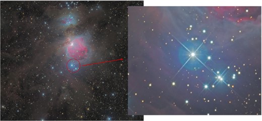
Photographs taken in Guangxi, China. This is an image of the SMC and the globular cluster 47 Tuc. Three bands (R, G, and B) were exposed for 5 min for a single image, with 10 images per band. Enlarging the image reveals diffraction colour streaks, indicating that the telescope reached its local limit of seeing.
The tube of the MST is shown in Fig. 8, which mainly includes the primary-mirror adjusting mechanism, fold-mirror adjusting mechanism, and focuser mechanism. The primary-mirror adjusting mechanism consists of three groups of six screws, and the three groups are evenly distributed at intervals of 120°. The fold-mirror adjusting mechanism is composed of four screws. In the process of adjustment, when the central screw is lengthened or shortened, the remaining three screws should be adjusted and placed on the mounting seat of the fold mirror to fix the fold mirror.
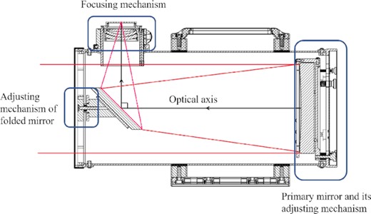
Schematic of the system structure.
To maximize the normal operation of the telescope and compensate for the optical path difference caused by the switching filter (particularly when loading the filter from the no-load state), it is necessary to equip the telescope with a focuser. MST uses three lenses for each tube to improve the phase difference, and these lenses are also used for focusing. The telescope’s focuser has a |$2\frac{1}{2}$|-inch, dual-speed rack-and-pinion design with 30 mm of travel.
Telescope alignment is a necessary condition for the successful operation of telescopes. Traditional telescope alignment requires external equipment such as micro-alignment telescopes. Considering the difficulty of alignment in Antarctica, we use a convenient new alignment scheme, which is reliable and feasible according to an analysis of Antarctic usage and is suitable for almost all Newtonian telescopes. Normal telescope alignment starts with the primary mirror and follows a ‘front to back’ sequence, but the MST uses a ‘back to front’ sequence, where the fold mirror is adjusted first, followed by the primary mirror. Owing to the Newtonian structure, we can easily observe the conditions of each element in the optical system from the exit window where the correction mirror set is located, as shown in Fig. 9. The first is the position of the fold mirror. The fold mirror of the MST is an ellipse when viewed from the front, but when properly installed in the telescope, it should be clamped at 45° to the optical axis (mechanical axis); that is, it should be a circle when viewed from the outgoing light port along the optical path (red circle in Fig. 9c). When the mirror appears to be a standard circle from the exit window and is at the mechanical centre (that is, the red and blue circles are concentric), the centre of the mirror is on the mechanical axis, and the surface normal of the mirror is at a 45° angle with the mechanical axis, which is the theoretical design position. At this time, the optical axis has been deflected by 90°. Then, on this basis, the posture of the primary mirror is adjusted so that the optical axis of the primary mirror coincides with the optical axis after the fold mirror. Because the primary mirror has been marked at the centre during processing and the primary mirror can be observed from the exit window, this step is relatively obvious and easy to adjust. Fig. 9 presents two common misalignment situations. Panel b in Fig. 9 shows the error caused by the translation of the mirror. In this case, although the angle between the mirror and the mechanical axis is 45°, the mirror is not at the mechanical centre. Panel c in Fig. 9 shows the case of the tilt of the mirror. In this case, although the mirror is at the mechanical centre, the red circle of the mirror is an ellipse instead of a standard circle.
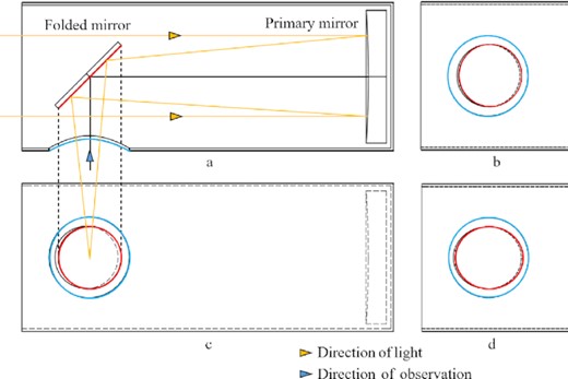
Schematic of MST alignment. The blue arrow indicates the observation direction and the yellow arrow indicates the direction of the optical path. The blue circle represents the viewing window and the red circle represents the edge of the mirror. When the mirror is aligned, the red circle is the accurate circle and is concentric with the blue circle. c and d show the conditions observed when the mirror is shifted and tilted, respectively, where the red circle is not concentric with the blue circle or the red circle is an ellipse.
3 PERFORMANCE
3.1 Commissioning
The design and trial assembly of the MST were completed in Nanjing, China, in October 2021, and the MST arrived in Antarctica in March 2022. It was successfully installed at Zhongshan Station in Antarctica to conduct observation. The MST will be used to survey the southern sky during the first polar night in Antarctica. Fig. 10 shows the installation of the MST. Although the environment in Antarctica is harsh during the polar night, the MST has operated successfully thus far. This chapter focuses on the state of the MST.
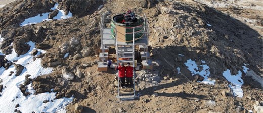
Photograph taken in March 2022, when the MST was successfully installed in Antarctica.
The MST has been debugged for more than a month. To measure its operation status, we use the method of analysing the full width at half maximum (FWHM) distribution of the full FOV. Fig. 11 shows the change in the full FOV FWHM distribution map of the MST from March 10 to April 29. There is an obvious misalignment in the left picture. First, the centre of the optical path is obviously not at the centre of the camera. Second, the spot size ranges from 5 to 25 pixels, and the maximum difference of 20 pixels is unacceptable for the measurement, according to a preliminary simulation analysis. In this case, the fold mirror may have a deflection of approximately 0.5°, and after alignment on the right, we can see that the optical path is essentially at the centre of the FOV, and the spot size is approximately 4–8. Fig. 12 shows the statistics of stars. At present, the average diameter of the MST spot is 5.7 pixels, and the RMS value is 5.5 pixels, most of which are concentrated in approximately 5 pixels, which is suitable for astrometry and polychromatic photometry. The spot distribution is uniform throughout the 6° FOV, indicating that this method is effective and feasible for optical-path adjustment of the MST. However, the maximum value of FWHM is still a little bit large; it indicates that MST needs further alignment; on the other hand, we think one of the most likely reasons is the deformation of the primary mirror. The primary mirror of MST is made of ordinary material, which produces mechanical deformation in the low-temperature environment and alignment.
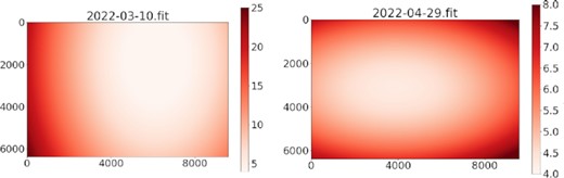
Full FOV FWHM distribution of the MST. The left picture corresponds to March 10 and the right picture corresponds to the analysis performed on April 29; the unit is the number of pixels.
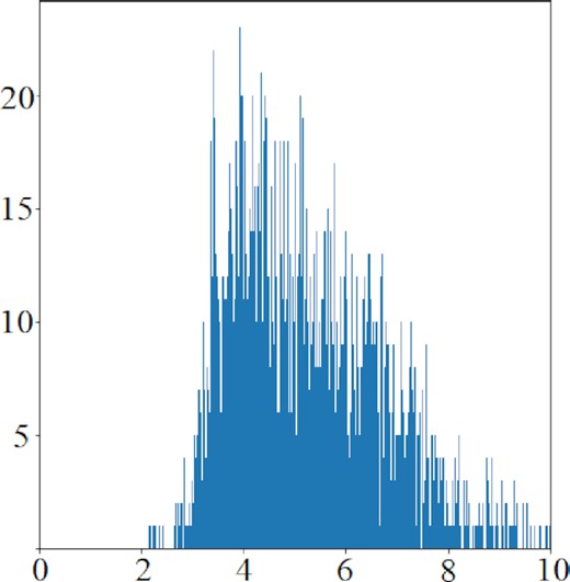
Star statistical analysis of the picture taken by the MST on April 29. The abscissa indicates the star FWHM diameter, in terms of the number of pixels, and the ordinate indicates the number of stars. The RMS value of FWHM diameter is 5.5 pixels.
Fig. 13 shows a picture taken by the MST at Zhongshan Station after alignment. The observation ability of the MST was confirmed through preliminary installation and adjustment. Additionally, it was confirmed that our preparations, such as the heated-window sealing, played the expected roles.
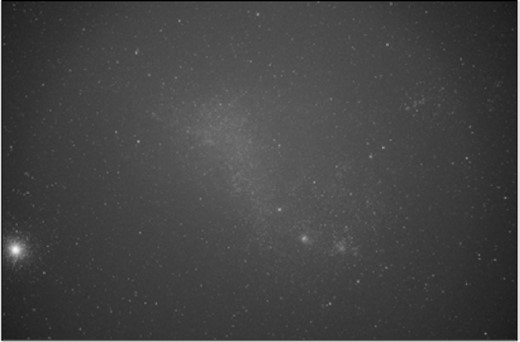
Star image obtained by the MST in Antarctica.
3.2 Tracking accuracy
In Antarctica, telescopes are inevitably affected by snow. Fig. 14 shows the status after a few months in Antarctica. As expected, MST’s transmission structure is almost completely covered by snow.
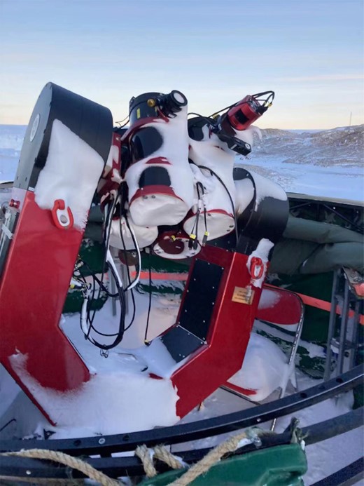
The situation of the MST after overwintering in Antarctica. Owing to adequate design preparation, the MST has resisted the harsh environment in Antarctica and is still in normal operation.
We have been paying close attention to the operation of the MST – particularly the effects of snow cover and low temperatures on the tracking accuracy. Fig. 15 shows our latest measurement of the MST tracking accuracy, which was performed on 2022 September 28. We randomly selected a star and tracked it for approximately 30 min. According to the actual measured data, the stellar velocity tracking accuracy was 0.41 arcsec, where RA RMS = 0.33 arcsec and DEC RMS = 0.24 arcsec, which met our design requirements (0.5 arcsec).
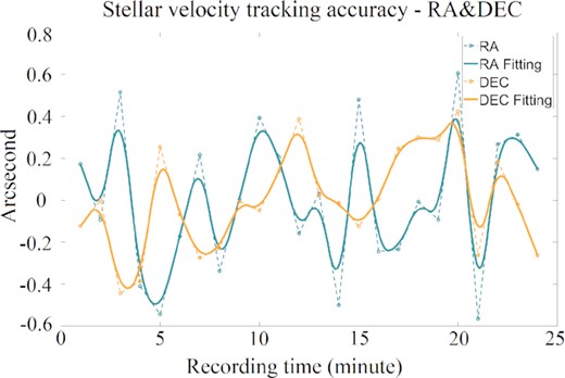
Tracking accuracy of the MST for a star over approximately 30 min in Antarctica. RA RMS = 0.33 arcsec, DEC RMS = 0.24 arcsec.
3.3 Image quality
To evaluate the image quality, we captured several images on June 22 with an exposure time of 0.2 s. The weather and polar light conditions were stable, and the image quality was similar during the observation; thus, one of the images was selected randomly to measure the image quality. The image was divided into 3 × 3 regions, and in each region, a bright unsaturated star was selected to examine the stellar point spread functions (PSFs). Around each star, a 25 × 25 pixels cut-out was extracted after background subtraction. The results are shown in Fig. 16.
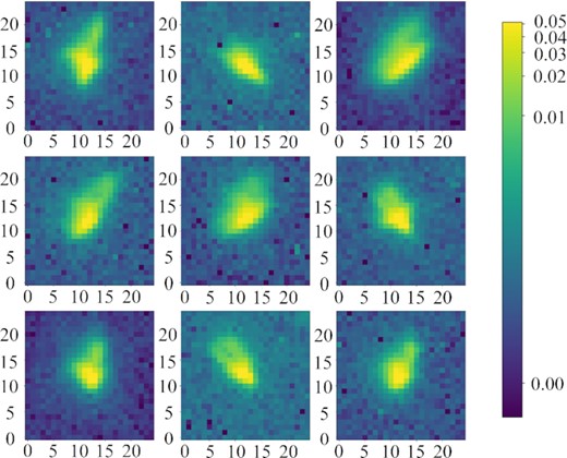
The PSF distribution of unsaturated stars in a 3x3 grid pattern across the image.
In most of the image, besides the main part of the star, there was a weak tail, and the direction of the tail depended on the position. The average FWHM on the image is about 5 arcsec.
3.4 Photometry
Images taken on the night of June 17 were used for measuring the photometric precision. The telescope was equipped with four filters (L, R, G, and B), and the L band filter was used. We captured 20 images of the sky and the exposure time was 600 s. Because the PSF was not optimal, aperture photometry was applied. We used the Source-Extractor software to extract the sources. The isolated magnitude was applied, and we used several bright unsaturated main sequence stars from the SIMBAD database to calibrate the magnitude to the standard V-magnitude. The RMS of the magnitude estimates of the same stars taken in six continuous images are obtained as the magnitude errors. The results are shown in Fig. 17 and the median magnitude errors in 1 magnitude bin are also plotted in the red line. The increasing errors brighter than the 6 magnitude are due to saturation.
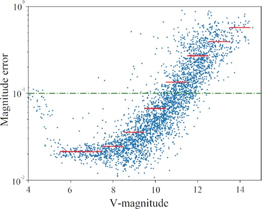
The V band magnitude and statistical errors are estimated from six continuous images with 600 s exposure. The median magnitude errors in the 1 magnitude bin are plotted in red line. The magnitude error of 0.1 is masked with horizontal green dotted lines.
3.5 LEO tracking precision
To evaluate the ability of the MST to track low-Earth objects (LEOs), an experiment was performed. We let the telescope track a satellite according to the predicted orbit and checked the drift of the satellite spot in the images. The experiment was conducted on August 20 and the LEO test was performed at approximately 770 km height.
We selected this object because it was bright, had a relatively low orbit, and travelled fast. The typical observable time of each pass was several minutes. Because the satellite travelled fast across a large portion of the sky, at long time intervals, the tracking accuracy would have been reduced by an imperfect pointing model. Thus, we captured an image sequence with a short exposure time of 0.1 s, and each sequence was finished in a 30 s period. Finally, 27 images were obtained during one pass of the satellite and the light mass centres were measured for each image. We plotted the histogram of the distances from the centres to their mean value, as shown in Fig. 18. The standard deviation of the distance was 1.48 pixels or 2.5 arcsec. Note that the tracking precision is also affected by the prediction accuracy of the orbit, and a poor PSF reduces the precision; thus, this value can be treated as the lower limit of the telescope mount-tracking precision for LEOs.
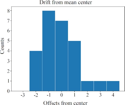
Histogram of the drifts of the satellite from the mean centre in a 30 s interval. The standard deviation of the distribution is 1.48 pixels or 2.5 arcsec.
4 SUMMARY
The MST – the first multicolour simultaneous photometric survey telescope to be deployed in Antarctica – will play a unique role in increasing the photometric accuracy and improving the quality of sky surveying. In addition, the MST will exploit the unique latitude location of Antarctica to certify exoplanets. The MST underwent the process of design, assembly, transportation, and alignment and withstood long and harsh winter nights in Antarctica. Although the MST has not reached the design target with regard to image quality, it has been used to verify the feasibility of related technologies, telescope automation, and unattended programmes, which provided valuable experience for later larger Antarctic telescopes. Considering the loose tolerance given in the design, the difference between the results of the analysis and the actual observation, especially the difference in its performance in China and Antarctica, we think that the main reason is the surface deformation of the primary mirror.
We expect to replace all the primary mirror materials of MST this year or next year, and if all goes well, we will install a larger (300-mm aperture) telescope at the same time.
We will continue to test MST in Antarctic stations and optimize the design and manufacture, and develop MST as a standard model of small-aperture Antarctic telescope. In future, we plan to deploy MST arrays in Zhongshan, Taishan (Tian et al. 2020), and Kunlun stations for space debris observations and time-domain surveys.
ACKNOWLEDGEMENTS
The authors thank the Polar Research Institute of China and Suzhou ZWO company , Jiaxing Ruixing company, and Professional Astronomical Instruments company for their support and cooperation. This work was supported by the National Natural Science Foundation of China (Grant Nos. 11973037 and 12173062) and National key research and development program (Grant No. 2022YFC2807301).
DATA AVAILABILITY
The data underlying this article will be shared on reasonable request to the corresponding author.
