


ABSTRACT
Compact Obscured Nuclei (CONs) potentially hide extreme supermassive black hole (SMBH) growth behind large column densities of gas/dust. We present a spectroscopic analysis of the heavily obscured nucleus and the surrounding environment of the eastern region of the nearby (z = 0.02007) interacting galaxy VV 114 with the JWST Mid-InfraRed Instrument (MIRI). We model the spectrum from 4.9 to 28 μm to extract polycyclic aromatic hydrocarbon (PAH) emission and the underlying obscured continuum. We find that the NE nucleus (A) is highly obscured where the low PAH equivalent width (EW) ratio, EW(12.7)/EW(11.3), reveals a dust enshrouded continuum source. This is confirmed by decomposing the continuum into nuclear and star-forming where the nuclear component is found to be typical of CONs. The 11.3/6.2 PAH flux ratio is consistent with originating in star-forming regions rather than typical AGN. The second nucleus (B) is much less obscured, with PAH flux ratios also typical of star-forming regions. We do not detect any high ionization lines such as [Ne v] or [Ne vi] which suggests that if an AGN is present it must be highly obscured. Additionally, we detect a shock front south of the secondary nucleus (B) in the [Fe ii] (5.34 μm) line and in warm molecular hydrogen. The 6.2 PAH emission does not spatially coincide with the low-J transitions of H2 but rather appears strong at the shock front which may suggest destruction of the ionized PAHs in the post-shock gas behind the shock front.
1 INTRODUCTION
Luminous infrared galaxies (LIRGs; L|$_{\rm IR} \gt 10^{11} \rm {L}_{\odot }$|) and ultraluminous infrared galaxies (ULIRGs; L|$_{\rm IR} \gt 10^{12} \rm {L}_{\odot }$|) contain some of the most extreme dusty environments and disturbed morphology, with a high prevalence of major/minor galaxy mergers (e.g. Rigopoulou et al. 1999). These obscured environments hide some of the most intense and rapid galaxy evolution with high star-formation rates and supermassive black hole (SMBH) growth. Studying such environments is a challenge at optical wavelengths due to the high levels of dust extinction and therefore requires study at longer wavelengths. The JWST Mid-InfraRed Instrument (MIRI) enables the study of these environments in the mid-infrared at a significantly improved spatial/spectral resolution and sensitivity compared to previous facilities (Rieke et al. 2015; Wells et al. 2015; Wright et al. 2015).
The most obscured galactic nuclei, the so-called Compact Obscured Nuclei (CONs) show extreme column densities (|$N_{\rm {H}} \gt 10^{25} \rm {cm}^{-2}, A_{v} \gt 1000$| mag) (e.g. Aalto et al. 2019; Falstad et al. 2021, and references therein) where either a compact starburst or an accreting supermassive black hole (SMBH) is completely obscured. These objects are prevalent among LIRGs and ULIRGs in the local Universe (Falstad et al. 2021; Donnan et al. 2022; García-Bernete et al. 2022c) and therefore represent a crucial phase of galaxy evolution where rapid SMBH growth may occur, especially considering the increased prevalence of dusty galaxies towards cosmic noon (e.g. Magnelli et al. 2011).
Detecting such objects is a challenge due to their obscured nature with most studies being confined to the sub-mm regime (e.g. Aalto et al. 2015, 2019; Falstad et al. 2021). However recent work by García-Bernete et al. (2022c) in the mid-infrared has found that these objects can be identified by measuring the impact of obscuration on the mid-IR continuum compared to polycyclic aromatic hydrocarbon (PAH) emission which traces relatively unobscured star-formation in the circumnuclear region. The development of this technique is particularly timely as the recent launch of the JWST provides data in the mid-infrared with a significant increase in the spatial and spectral resolution over previous facilities.
To identify CONs using PAHs involves measuring the impact of the 9.8 μm silicate absorption feature on the continuum compared to the PAH emission, through the use of the ratio of the equivalent widths (EWs) of different PAH features. As the PAH emission originates from the relatively unobscured circumnuclear region, the presence of a highly obscured nucleus will cause deep silicate absorption at 9.8 μm and lower the continuum around the 11.3 μm PAH (García-Bernete et al. 2022c). This will increase its equivalent width relative to the other PAH features where the continuum is less affected by the extinction from the nucleus. Therefore the presence of a highly obscured nucleus can be revealed through lower values of the EW(12.7)/EW(11.3) and the EW(6.2)/EW(11.3) PAH ratios (García-Bernete et al. 2022c). Typical star-forming galaxies that do not host a highly obscured nucleus show a typically higher, approximately constant PAH EW ratio as the intrinsic flux ratio is approximately constant and the extinction of the PAHs and continuum cancel when taking the ratio (Hernán-Caballero et al. 2020; García-Bernete et al. 2022c).
In this work, we apply the technique to JWST data for the first time with MIRI observations of the highly obscured interacting system VV 114 (IC 1623, Arp 236). This is a local (z = 0.02007, D = 84 Mpc; Strauss et al. 1992) galaxy with a highly disturbed morphology. This object is a LIRG with LIR = 1011.71 L⊙ (Armus et al. 2009) and is in the mid-stages of a major merger (Stierwalt et al. 2013). The western region of this galaxy is much more prominent in the UV/optical (e.g. Frayer et al. 1999; Evans et al. 2022) whereas the eastern region is extremely dust rich, appearing very red in the optical. Moving towards the infrared, the luminosity of the eastern region dramatically increases (e.g. Charmandaris, Le Floc’h & Mirabel 2004) and dominates over the western region. Therefore the eastern region is ideal for testing the diagnostic power of JWST/MIRI for extremely obscured environments.
The eastern region contains complex morphology with clumps of star formation, shocks (Rich, Kewley & Dopita 2011) and a potential buried AGN (Saito et al. 2015). This nucleus is a very good CON candidate considering the heavy obscuration and potential AGN power source. From Spitzer spectral mapping observations Donnan et al. (2022) found that the PAH EW ratios approached those that might indicate a CON as the aperture size was reduced towards the nucleus, however the low angular resolution meant that the spectrum was heavily diluted by the circumnuclear star formation. The low angular resolution of Spitzer (PSF FWHM of ∼3.8 arcsec at 14 μm which corresponds to an angular size of ∼ 1.6 kpc) meant that the eastern region of VV 114 was completely unresolved in the spectral mapping mode with no structure visible. The almost factor of ∼10 increase in the spatial resolution of JWST/MIRI MRS (PSF FWHM of ∼0.48 arcsec at 14 μm which corresponds to an angular size of ∼ 200 pc) allows spatially resolved spectroscopic analysis of the eastern region of VV 114, where the previously unresolved region now shows multiple ‘nuclei’ and a very complex morphology.
The eastern region of VV 114 has been observed with JWST as part of Early Release Science Programme 1328 (PI: Lee Armus) with MIRI imaging (Evans et al. 2022) and MIRI MRS. We use this data to demonstrate the diagnostic power of mid-infrared spectroscopy to reveal highly obscured nuclei.
In Section 2 we describe the data and reduction steps. In Section 3 we outline our modified version of PAHFIT to fit JWST spectra. By applying this fitting tool we measure the obscuration, properties of the various regions through their PAH features. By generating line maps we measure the fine structure lines and molecular hydrogen (H2) transitions that are tracing a shock in Section 4. We then discuss a possible evolutionary scenario in Section 5.
2 OBSERVATIONS
To illustrate the region of VV 114E we show imaging from MIRI (Evans et al. 2022) with a colour composite image in the left-hand panel of Fig. 1. We used the reduced data from the MAST archive1 to construct this image. There are however some issues with this reduction where the dithered observations within a single filter have not been properly aligned, which can be seen by the diffraction spikes splitting into three. As we are using the image for illustration only for purposes, this is not a major issue.

Left-hand panel: Colour composite image of VV 114E using JWST/MIRI. The F560W (blue) and F1500W (red) trace mostly continuum while the F770W (green) traces the 7.7 μm PAH feature. The two main point sources are labelled A and B. Right-hand panel: Integrated intensity (moment 0) map of Channel 1 (4.90–7.65 μm) which is dominated by thermal continuum dust emission and the 6.2 μm PAH which is more spatially extended. The black circles show the apertures used to extract the spectra shown in Fig. 2, labelled A, B, and C.
Two main point sources are apparent in this image, labelled A and B. Source A is significantly redder than B and is the suggested buried AGN from ALMA observations (Saito et al. 2015) where the continuum remains unresolved in the millimetre. Source B shows a stronger continuum in the F560W band relative to F1500W compared to source A. There are numerous other small clumps appearing within the image however, most of these are beyond the field of view of the MIRI-MRS observations. The F770W filter, centred on the 7.7 μm PAH shows much more extended emission and traces areas of star formation where young stars radiatively excite PAH molecules.
2.1 MIRI MRS reduction
MIRI MRS data consists of four subcubes with channel 1 (4.9–7.65 μm), channel 2 (7.51–11.71 μm), channel 3 (11.55–18.02 μm) and channel 4 (17.71–28.1 μm) with an increasing field of view and pixel size towards longer wavelengths.
We downloaded the MIRI MRS level 2-b reduced data from the MAST archive and constructed the 4 sub-cubes using the Spec3 pipeline (version 1.6.2). Before running the Spec3 pipeline we performed the residual fringe subtraction step separately to remove fringing still present after the fringe correction step of the pipeline. Using the jwst|$\_$|0913.pmap context of the CRDS we ran the Spec3 pipeline to produce 4 sub-cubes and their corresponding backgrounds. We estimated the background for each wavelength channel by calculating the median in each channel of the background cubes before subtracting, following the same method as in García-Bernete et al. (2022a).
To ensure the extracted spectra are from the same spatial position, we first correct for small discrepancies in the WCS and spatially align all the sub-channels. We use the DAOStarFinder algorithm (Stetson 1987) from the photutils python package to find the position of point sources in the integrated intensity (moment 0) maps which trace the continuum of each of the four subchannels. We then adjust the WCS header to align the measured point sources. Subsequently, we extract the spectrum using a circular aperture with a 1 arcsec diameter centred on the measured position. We do this for the two point sources in the image (A and B) and apply the correction factor from Pereira-Santaella et al. (2022) for this aperture (see also García-Bernete et al. 2022a). We also extract the spectrum from a region where no source is present to represent the extended emission (point C). We chose an aperture placed away from the two point sources so as to not be contaminated by the PSF at the longest wavelengths but close enough such that it is within the field-of-view in the shortest wavelength channel. As the emission within aperture C is not a point source we do not apply the aperture correction factor. The three apertures are shown in the right-hand panel of Fig. 1.
The three spectra are shown in Fig. 2 where the extended emission (source C) shows the strongest emission features compared to source A and B which both show a strong continuum. Source A is clearly the more obscured one showing very deep silicate absorption at 9.8 and 18 μm. There is also evidence for absorption due to water ice and aliphatic CH around 6 and 7.5 μm, respectively. The spectrum of source B shows a strong continuum around 5–6 μm, consistent with the colours seen in the imaging in Fig. 1 and Evans et al. (2022).
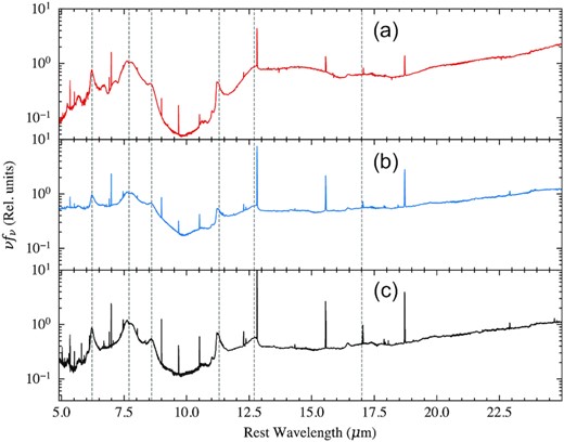
MIRI/MRS spectra of three regions in VV 114E. Spectra A and B are extracted as point sources using a 1 arcsec circular aperture with a PSF wavelength dependent correction factor applied. Source C represents extended emission without the presence of any point sources. The fluxes are normalized to 7.7 μm. The most prominent PAH features are labelled with the vertical dashed lines.
3 METHODS
3.1 Spectral fitting
By modelling the entire spectrum, we can obtain emission line/PAH fluxes and extinction features using all of the available MIR data to constrain the various components. A widely used tool from the Spitzer era was PAHFIT (Smith et al. 2007) which decomposes the spectrum into various emission lines, PAH features, a dust continuum and corresponding extinction. We use our own modified version of PAHFIT which has been fine tuned to model JWST spectra with additional PAH features, emission lines, and extinction features. The following sections describe the various components of the model.
3.1.1 Emission Lines
The mid-infrared wavelength regime is host to various emission lines including molecular hydrogen (H2) lines and ionized fine structure lines in addition to the PAH emission.
Spectral lines.
| Line | λ0 | FWHM (|$\pm 50$| per cent) |
|---|---|---|
| μm | μm | |
| (1) | (2) | (3) |
| H2 S(8) | 5.053 | 0.0015 |
| [Fe ii] | 5.340 | 0.0015 |
| [Fe viii] | 5.447 | 0.0015 |
| H2 S(7) | 5.551 | 0.0015 |
| [Mg v] | 5.609 | 0.0015 |
| H2 S(6) | 6.109 | 0.0015 |
| H2 S(5) | 6.909 | 0.0015 |
| [Ar ii] | 6.985 | 0.0015 |
| H i 6-5 | 7.460 | 0.003 |
| [Ar v] | 7.901 | 0.003 |
| H2 S(4) | 8.026 | 0.003 |
| [Ar iii] | 8.991 | 0.003 |
| H2 S(3) | 9.665 | 0.003 |
| [S iv] | 10.551 | 0.003 |
| H2 S(2) | 12.278 | 0.008 |
| H i 7-6 | 12.370 | 0.008 |
| [Ne ii] | 12.813 | 0.008 |
| [Cl ii] | 14.322 | 0.008 |
| [Ne iii] | 15.555 | 0.008 |
| H2 S(1) | 17.035 | 0.008 |
| [P iii] | 17.885 | 0.010 |
| [Fe ii] | 17.936 | 0.010 |
| [S iii] | 18.713 | 0.010 |
| [Fe iii] | 22.925 | 0.010 |
| [Ne iv] | 24.318 | 0.010 |
Notes. Column (1): Line name, Column (2): Vacuum wavelength, Column (3): Line FWHM allowed to vary by |$\pm 50$| per cent of the value shown
Additional emission lines not present in the original PAHFIT (Smith et al. 2007) are shown in bold.
We find that the Lorentzian component is required to fit the base of the lines. This may compensate for issues with the current wavelength calibration in the data reduction pipeline (García-Bernete et al. 2022a; Pereira-Santaella et al. 2022; Rigby et al. 2022). As the majority of the flux of the line is not contained within the wings, this has a negligible impact on the measured fluxes.
3.1.2 PAH emission features
The original version of PAHFIT modelled PAH features with a series of Drude profiles as shown in table 3 of Smith et al. (2007). With the increased spectral resolution of JWST/MIRI the PAH emission shows more resolved structure than with Spitzer data (also noted by García-Bernete et al. 2022a). We therefore update the PAH model with additional components which we show in Table 2. For each Drude feature we allow the central wavelength to vary by ±0.05 μm to account for uncertainties in the wavelength calibration with the JWST pipeline (Rigby et al. 2022). We also allow the width of each feature to vary. In this case we allow the width to vary between |$+10 $| per cent and |$-60 $| per cent of the values shown in Table 2 where this range allows the PAH features to be narrower than the previous version of the tool due to the increased spectral resolution afforded by MIRI/MRS.
PAH features.
| λ0 (±0.05 μm) | Average λ0 | FWHM (+10 per cent, −60 per cent) | Average FWHM |
|---|---|---|---|
| μm | μm | μm | μm |
| (1) | (2) | (3) | (4) |
| 5.24 | 5.253 | 0.058 | 0.032 |
| 5.27 | 5.266 | 0.179 | 0.138 |
| 5.70 | 5.699 | 0.200 | 0.153 |
| 5.87 | 5.856 | 0.200 | 0.119 |
| 6.00 | 6.019 | 0.200 | 0.085 |
| 6.18 | 6.214 | 0.100 | 0.105 |
| 6.30 | 6.329 | 0.187 | 0.206 |
| 6.69 | 6.705 | 0.468 | 0.515 |
| 7.42 | 7.427 | 0.935 | 0.942 |
| 7.60 | 7.587 | 0.334 | 0.249 |
| 7.85 | 7.841 | 0.416 | 0.432 |
| 8.33 | 8.293 | 0.417 | 0.423 |
| 8.61 | 8.602 | 0.336 | 0.296 |
| 10.68 | 10.630 | 0.214 | 0.229 |
| 11.00 | 10.978 | 0.100 | 0.063 |
| 11.15 | 11.191 | 0.030 | 0.023 |
| 11.20 | 11.211 | 0.030 | 0.028 |
| 11.22 | 11.244 | 0.100 | 0.043 |
| 11.25 | 11.291 | 0.135 | 0.077 |
| 11.33 | 11.380 | 0.363 | 0.362 |
| 11.99 | 11.956 | 0.540 | 0.594 |
| 12.62 | 12.635 | 0.530 | 0.573 |
| 12.69 | 12.738 | 0.120 | 0.111 |
| 13.48 | 13.439 | 0.539 | 0.593 |
| 14.04 | 13.990 | 0.225 | 0.248 |
| 14.19 | 14.207 | 0.355 | 0.390 |
| 14.65 | 14.639 | 0.500 | 0.384 |
| 15.90 | 15.851 | 0.318 | 0.276 |
| 16.45 | 16.459 | 0.230 | 0.156 |
| 17.04 | 17.023 | 1.108 | 0.877 |
| 17.375 | 17.389 | 0.209 | 0.190 |
| 17.87 | 17.887 | 0.286 | 0.258 |
| 18.92 | 18.937 | 0.359 | 0.395 |
Notes. Column (1): Initial central wavelength for the fit with range ±0.05 μm. Column (2): Average best-fitting central wavelength. Column (3): Initial FWHM allowed to vary within |$+10 $| per cent and |$-60 $| per cent. Column (4): Average best-fitting FWHM.
Additional Drude profiles not present in the original PAHFIT (Smith et al. 2007) are shown in bold.
3.1.3 Continuum
For each spectrum we sample the posterior probability using the No-U-Turn Sampling (NUTS) Markov–Chain Monte Carlo (MCMC) from numpyro (Phan, Pradhan & Jankowiak 2019). This allows posterior probabilities to be obtained from properties inferred from the spectra.
We fit the spectra of the three regions as described in Section 2. We show these fits in Fig. 14 (Appendix B). In columns (2) and (4) of Table 2 we show the average PAH centres and average FWHMs from these three fits which can be used to update future PAH models in various spectral fitting codes. We also fit various star-forming clumps from the MRS spectra of NGC 7469 (García-Bernete et al. 2022c) to provide a small but representative reference sample of pure star-forming regions.
In Fig. 3 we show the 6.2, 7.7, 11.3, 12.7, and 17 μm PAH bands for region C with the best-fitting model. We show region C as it showed the strongest PAH emission features. With the increased spectral resolution of JWST/MIRI we can reveal new resolved features in the PAH profiles. In particular the 6.2 μm PAH is now asymmetric which we now fit with two Drude profiles rather than a single one. This asymmetry can be somewhat seen in ISO (Infrared Space Observatory) observations (e.g. Verstraete et al. 2001), which had a higher spectral resolution than Spitzer in its low resolution mode. The 11.3 μm feature also shows more resolved structure which we fit with four profiles compared to two in the original PAHFIT (Smith et al. 2007).
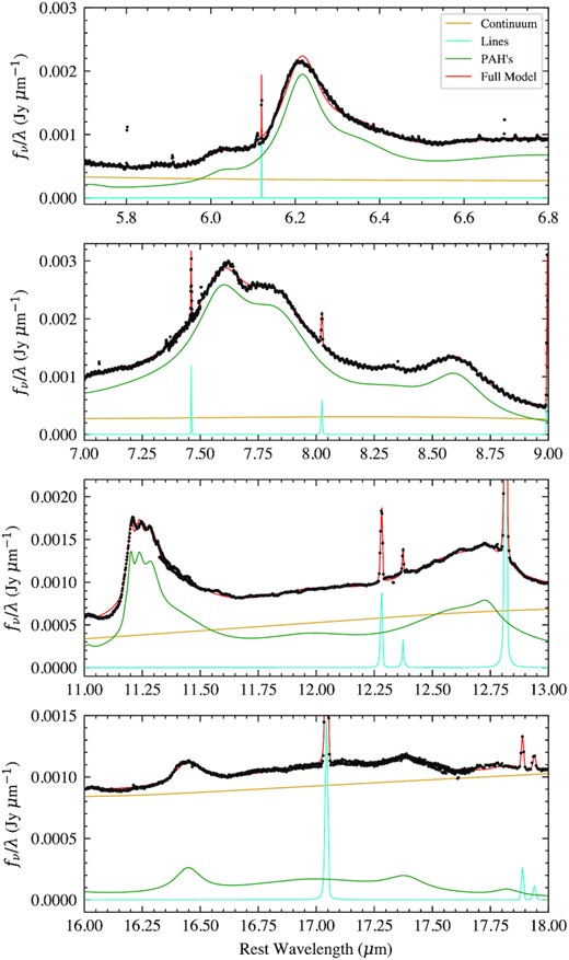
Panels showing the main PAH bands at 6.2, 7.7, 8.6, 11.3, 12.7, and 17 μm for region C. The best-fitting PAHFIT model is shown in red with it constituent components labelled in the legend. The emission lines are identified in Table 1.
We typically found that the errors of measured properties from the MCMC routine were very small. The standard deviation of the normalized residuals was much greater than 1 for all of the model fits which suggests the errors of the data are underestimated and thus our parameter errors are too small. We therefore scaled the measured parameter errors by that required to achieve normalized residuals with a standard deviation of 1 to give a more conservative estimate for the uncertainties.
3.2 Emission line maps
To study how the emission line fluxes are spatially distributed we generate maps using a local continuum and integrating to obtain the line flux. For each spaxel we extract a spectrum at wavelengths around the emission line. We mask the data points of the emission line, smooth the data using a Gaussian kernel, and interpolate across the masked region with a cubic spline to produce a local continuum. We then subtract the local continuum from the data and integrate to measure a line flux. This is done for each spaxel to produce a map of the emission line flux.
To estimate error maps for these lines, we first estimate the noise in the flux data (fν(λ)) by finding the standard deviation of the data after subtracting the local continuum and masking the emission line. We do this rather than using the flux error bars as these are likely underestimated as noted in the previous section. We then propagate the errors in fν to find the error in the integrated flux of the emission line for each spaxel to obtain an error map.
To ensure accurate line fluxes in such a heavily obscured environment extinction corrections need to be applied. Obtaining accurate extinction corrections is a challenge in such a complex environment as different components of the spectrum may be affected by different levels of extinction.
To do this we generate a map of the optical depth at each spaxel by measuring the silicate depth at 9.8 μm. This is done by linearly interpolating between 6.7 and 13 μm to approximate an underlying continuum from which the silicate depth was measured using equation (6). We assume a 10 per cent contribution at 9.8 μm from a power-law component and increase the measured silicate depth by a factor 1/0.9 to estimate τ9.8. This results in the map shown in Fig. 4, which we use to correct any emission line map by extinction using our extinction curve as discussed in Appendix A.
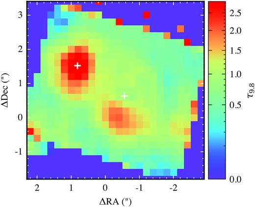
Extinction map. Optical depth at 9.8 μm derived from the silicate depth using an interpolated continuum as discussed in Section 3.2. This map is used to correct any emission line maps by extinction. The white crosses show the position of the continuum from source A and B.
4 RESULTS
4.1 Obscuration
4.1.1 PAH EW ratios
To investigate the nature of the two nuclei and the extended emission, in particular the presence of a highly obscured nucleus, we measure the PAH EW ratios of the 12.7 μm over the 11.3 μm and the 6.2 μm over 11.3 μm PAH features in order to construct a PAH EW diagram (García-Bernete et al. 2022c). These ratios are shown in Fig. 5. For star-forming regions we expect an approximately constant PAH EW ratio (Hernán-Caballero et al. 2020; García-Bernete et al. 2022c). Because of the enhanced spectral resolution afforded by MIRI/MRS, we had to redefine the CON selection region using JWST reference spectra of star-forming regions. We do this as the increased spectral resolution of MIRI MRS compared to Spitzer IRS results in different values of the PAH EW ratios, and thus recalibration of the CON selection criteria is required. In particular, the 12.7 μm PAH is better resolved and thus has a higher EW than in the Spitzer data. To recalibrate the CON selection region we use the clumps observed in the starburst ring of NGC 7469 (García-Bernete et al. 2022a). These are shown as the grey points in Fig. 5. As more targets are observed with MIRI MRS, the sample of star-forming regions will expand and thus improve the CON selection criteria.
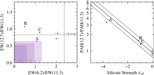
Left-hand panel: PAH EW diagram (García-Bernete et al. 2022c) for the three regions in VV 114E, labelled A, B, and C. The grey points show the values found for star-forming clumps in NGC 7469 (García-Bernete et al. 2022a) with means shown as the grey lines. The selection criteria for highly obscured nuclei are shown as the purple box defined as either 3σ, 4σ, or 5σ from the mean of the star-forming clumps. Right-hand panel: Plot of the 12.7/11.3 PAH flux ratio as a function of extinction as measured by the strength of the 9.8 μm absorption feature as given by equation (6). The grey points show the star-forming clumps for NGC 7469, from which the mean flux ratio subject to extinction from our custom extinction curve (see Appendix A) is plotted as the black line with |$\pm 20$| per cent intervals shown as the dashed lines. This line shows how the flux ratio is expected to change as a function of extinction.
From these star-forming clumps, we measure the mean and standard deviation, σ, of the EW(12.7)/EW(11.3) and EW(6.2)/EW(11.3) ratios where the obscured nuclei selection region is defined as values lower than nσ from this mean. We show 3σ, 4σ, and 5σ thresholds in Fig. 5.
We also show the expected 12.7/11.3 PAH flux ratio as a function of the extinction as measured by the silicate strength (equation 6) in the right-hand panel of Fig. 5. To construct this, we first measure the intrinsic flux ratio from the star-forming clumps of NGC 7469 as these show practically no extinction with a silicate strength of very close to zero (García-Bernete et al. 2022a). We then apply extinction to this ratio using our extinction curve and measure the resulting PAH flux ratio. This is shown as the black line with the dashed lines denoting |$\pm 20$| per cent. Obscured star-formation is expected to lie along this line assuming the PAH emission traces star-formation (Hernán-Caballero et al. 2020; García-Bernete et al. 2022c).
Source A shows lower EW(12.7)/EW(11.3) and EW(6.2)/EW(11.3) with both values below 3σ of the star-forming clumps. This indicates the presence of an obscured nucleus. This is further shown in the right-hand panel of Fig. 5 where the 12.7/11.3 PAH flux ratio is lower than expected for the level of extinction (indicated by the silicate strength) measured on the continuum. This suggests additional extinction on the continuum compared to the PAH emission and thus the presence of a deeply buried nucleus.
Source B shows a raised EW(12.7)/EW(11.3) but a significantly lower EW(6.2)/EW(11.3). This is where typical AGNs are observed in the PAH EW ratio diagram in García-Bernete et al. (2022c), which the authors attributed to a flatter continuum around the 11.3 μm PAH, due to contribution from silicates in emission. The low EW(6.2)/EW(11.3) is also expected for AGN as the presence of hot dust elevates the continuum around 6 μm resulting in a low 6.2 PAH EW. This is consistent with the blue MIRI image which Evans et al. (2022) point out is typical of AGN.
Region C shows an EW(12.7)/EW(11.3) consistent with the star-forming clumps as expected as this aperture traces the extended PAH emission which is likely pure star-formation. It does however show a significantly lower EW(6.2)/EW(11.3) which could be due to a bluer continuum, raising the EW of the 6.2 μm PAH.
4.1.2 Spectral decomposition
To further assess whether nucleus A contains a highly obscured source, we model the spectrum by decomposing it into a star-forming and nuclear component. We follow the same method as from Donnan et al. (2022) to do this. This model fits the 5.2–14.2 μm spectrum with a star-forming continuum using templates from a calibration sample (Hernán-Caballero et al. 2020) and a nuclear continuum that is heavily obscured. The nuclear continuum is composed of a smooth spline and a silicate template (derived from IRAS 08572+3915) where the optical depth, τN, of this template is a free parameter.
To properly decompose the spectra, we use a Bayesian process where priors are used to break the degeneracy between the two components. We assume that the PAH emission is associated with star formation (the PAH ratios in Section 4.2 are consistent with this) and therefore we place a tight prior on the total PAH flux, fPAH, to the star-forming continuum flux, fSF, between 5.2 and 14.2 μm. We use a normal prior of fPAH/fSF = 1.92 ± 0.56 as inferred from the Hernán-Caballero et al. (2020) calibration sample in Donnan et al. (2022). We use the silicate profile of IRAS 08572+3915 for the nuclear component, where this component is constrained through its contribution to the total flux where the star-forming continuum is tied to the total PAH flux via the aforementioned prior.
This results in the decomposition in Fig. 6 where we measure a nuclear optical depth of |$\tau _N = 5.581^{+0.006}_{-0.007}$| and a nuclear fraction of |$\beta = 0.772^{+0.001}_{-0.001}$| (β is defined as the fractional contribution to the total continuum flux between 5.2 and 14.2 μm). It is worth noting that these uncertainties are likely underestimated by a factor of ∼10 as mentioned previously. These results show that the spectrum of source A can be explained by a low contribution from less obscured star formation in the foreground in addition to a highly obscured nucleus with a deep silicate absorption feature, which dominates the spectrum. To place this optical depth in context we show a modified plot from fig. B1 of Donnan et al. (2022) where the measured nuclear optical depths from Spitzer spectra of the CONquest sample (Falstad et al. 2021) are plotted against the HCN-vib surface brightness as measured in the millimetre, using the same IRAS 08572+3915 silicate template used here. This is shown in Fig. 7. Placing the τN = 5.6 onto this plot finds a HCN-vib surface brightness of ΣHCN-vib ≳ 1L⊙ pc−2, which above the threshold to be considered a CON (Falstad et al. 2021).
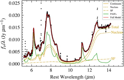
Fit to the spectrum of source A using the decomposition model described in Section 4.1 and Donnan et al. (2022). This model fits the spectrum up to 14.2 μm by decomposing the continuum into star forming and nuclear where the relative contributions are constrained by restricting the total PAH flux to the total star-forming continuum flux. The total continuum is given by the solid line and is the sum of the two components.
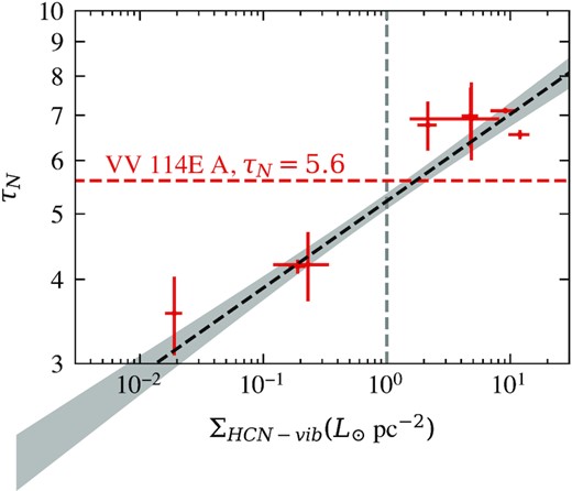
Plot modified from Donnan et al. (2022) which shows the nuclear optical depth of the CONquest sample (Falstad et al. 2021) measured using the spectral decomposition method and plotted against the surface brightness of HCN-vib. We show the CON definition of ΣHCN-vib > 1 L⊙ pc−2 with the vertical dashed grey line. The horizontal red line shows the value of τN = 5.6 found for VV 114E A, which predicts a ΣHCN-vib > 1 L⊙, meeting the CON definition.
4.2 PAH properties
The relative fluxes between different PAH emission features are known to change with the properties of the PAH molecules and the incident radiation field (see Li 2020, for a recent review).
In the immediate vicinity of AGN, PAH molecules are thought to be destroyed (e.g. Roche et al. 1991; Voit 1992; Siebenmorgen, Krügel & Spoon 2004), however there is evidence that they can survive close to the AGN, in particular the 11.3 μm feature (Hönig et al. 2010; Alonso-Herrero et al. 2014, 2016; Jensen et al. 2017). Most recently García-Bernete et al. (2022a) found that PAHs can survive in the innermost region of luminous Seyfert galaxies using JWST/MRS data but that these PAHs are different to typical star-forming galaxies, where they are observed to be larger and more neutral (García-Bernete et al. 2022b, a).
For measuring the PAH properties in VV 114E, we avoid using the 7.7 μm PAH as the continuum around this feature is difficult to constrain properly due to both the CH absorption at ∼7.3 μm and the tail of the silicate absorption feature. We therefore employ the 11.3/6.2 ratio as a tracer of the ionization state of the PAH population (e.g. Rigopoulou et al. 2021). This was shown in García-Bernete et al. (2022b) to show distinct differences in the ratios between AGN and pure star-forming galaxies.
In Fig. 8 we show the 11.3/6.2 μm flux ratio after correcting for extinction. This ratio is expected to decrease with a greater fraction of ionized PAH molecules (Rigopoulou et al. 2021; García-Bernete et al. 2022b). We plot the measured ratios against the [Ne iii]/[Ne ii] line ratio which traces the hardness of the radiation field (these lines are investigated further in the following section) and compare against the average ratios for star-forming galaxies and AGN from García-Bernete et al. (2022b). We find all three sources to be consistent with typical star-forming galaxies where the PAH molecules are less neutral (higher fraction of ionized molecules) than typical AGN. This means that if any AGN is present then it must be extremely obscured leaving the PAH emission unaffected.
![PAH flux ratios of the 11.3 μm PAH over the 6.2 μm against the [Ne ii]/[Ne ii] line ratio which traces the hardness of the radiation field. A greater fraction of ionized PAHs will result in a lower value. The values labelled A, B, and C show those obtained from the three regions in VV 114E while the grey points show four star-forming clumps from NGC 7469 (García-Bernete et al. 2022a). The solid grey lines show the average value for star-forming galaxies (∼1) and AGN (∼2) from García-Bernete et al. (2022b). These ratios have been corrected by extinction.](https://oup.silverchair-cdn.com/oup/backfile/Content_public/Journal/mnras/519/3/10.1093_mnras_stac3729/1/m_stac3729fig8.jpeg?Expires=1750219748&Signature=za~8TpHGPqsu4bShKMgqzOdsYQTeWLYeWHsGnmyU2mXLc5h8-QZF2-6a-wG0cl9oQN2s-kaMdKjhwj3ROZQ7gzP2Cvdg~lRFZkq0~qwY-6IhF8dOy5a6RCd~4Qhj7-pF~kB-yqC~hjoDULkJDMcr3vnKERJwldsiAkEHg0FSxt5Ob7s~YL5zPDZ22A6Y2VonV1qSbdBVN9rop49grVcfEzSavMB2dLSedJ0t8BJCVxgwjNC7D5~NJtmskZBpxEmics~FhBLaT~dQmTf5OFWApb3-HJi~WgQ0LAeXo1RibUU~JwDQcdAj0-0uTSmGFyYslMMvsSG7pjD-fIu2bLXn6g__&Key-Pair-Id=APKAIE5G5CRDK6RD3PGA)
PAH flux ratios of the 11.3 μm PAH over the 6.2 μm against the [Ne ii]/[Ne ii] line ratio which traces the hardness of the radiation field. A greater fraction of ionized PAHs will result in a lower value. The values labelled A, B, and C show those obtained from the three regions in VV 114E while the grey points show four star-forming clumps from NGC 7469 (García-Bernete et al. 2022a). The solid grey lines show the average value for star-forming galaxies (∼1) and AGN (∼2) from García-Bernete et al. (2022b). These ratios have been corrected by extinction.
One concern would be that the extinction is not quite correct for the obscured source A. As discussed in Section 4.1, source A likely contains a buried continuum source which means our PAH fluxes are potentially overcorrected for extinction. This would change the 11.3/6.2 ratio, where overcorrecting for extinction would boost the 11.3 more than the 6.2. This would imply that the true 11.3/6.2 ratio is slightly lower than plotted which moves it more inline with the other points, further from the AGN average.
4.3 Fine structure lines
To investigate the hardness of the radiation field withing VV 114E we generated maps of [Ne ii] (12.813 μm, 21.56 eV) and [Ne iii] (15.555 μm, 40.96 eV). The lower ionization potential lines [Ne ii] and [Ne iii] are excellent tracers of star formation due to their high relative brightness. These maps are shown in Fig. 9. The errors in these lines are very low as seen in the error maps in the same figure.
![Low ionization potential line maps and their ratios. The top panels shows [Ne ii] (12.813 μm, 21.56 eV), [Ne iii] (15.555 μm, 40.96 eV), and [Cl ii] (14.37 μm, 12.97 eV) from left to right. The bottom panels show ratios of these lines. For each map the associated error map is shown directly below. Flux units are in 10−20 Wm−2. The continuum positions of sources A and B are shown with the white crosses.](https://oup.silverchair-cdn.com/oup/backfile/Content_public/Journal/mnras/519/3/10.1093_mnras_stac3729/1/m_stac3729fig9.jpeg?Expires=1750219748&Signature=Eu018hWJ7DgY~XLD4b8APmmK6Kb5ssAdfd9h3p7Zn1-TWtLhaAx1DS0OPLES7drgDWdDmeU3mPxkpsako3eQx~3pZQ~aS8Bcvqi2Mteml86z3j18tqGr6KRlMt1nJAtXTA0RYfgJlXaxYWUGuQZXWUNztQGlBLHUptifp3XKjoHVinE8FnrVFkgPCNGLbV~wy58LoaO-tK-epKCcirOVS3SUOtnZT0GTcBWIF4Sj~wC3LgdLx5FZZ5KPAihO--IkegYhbzHLPHtiNHLBFLkvfQzegiV8qYOJqK6g0wjNcsk0kSoKWj35CuvYafm33jIXE-HRzs~AHgwZkfnwWZzJVg__&Key-Pair-Id=APKAIE5G5CRDK6RD3PGA)
Low ionization potential line maps and their ratios. The top panels shows [Ne ii] (12.813 μm, 21.56 eV), [Ne iii] (15.555 μm, 40.96 eV), and [Cl ii] (14.37 μm, 12.97 eV) from left to right. The bottom panels show ratios of these lines. For each map the associated error map is shown directly below. Flux units are in 10−20 Wm−2. The continuum positions of sources A and B are shown with the white crosses.
We do not detect any of the higher ionization potential lines such as [Ne v] (14.322 μm, 97.1 eV) or [Ne vi] (7.652 μm, 126.2 eV), which are typical tracers of AGN activity (e.g. Sturm et al. 2002; Armus et al. 2006; Inami et al. 2013). This suggests that there is no opening angle to any potential AGN present and therefore if an AGN does exist, it must be highly obscured.
The [Ne iii]/[Ne ii] line ratio is higher for source B compared to source A and the immediate surrounding region. This points towards a harder radiation field within this cluster where the lack of [Ne v] suggests that this is likely a star-forming clump with a young stellar population rather than an AGN. This is consistent with the much bluer colours seen in the imaging in Fig. 1 and Evans et al. (2022). The [Ne iii]/[Ne ii] ratio for source A may trace the foreground star-formation as found by the spectral decomposition in Section 4.1 as it appears similar to the surrounding environment.
We additionally detect the faint [Cl ii] (14.37 μm, 12.97 eV) line which has a very low ionization potential. Due to its faintness it was difficult to detect with Spitzer however the line has been observed in NGC 4945 (Pérez-Beaupuits et al. 2011) where it appeared to be more diffuse than [Ne ii]. This is indeed the case with VV 114E where in Fig. 9 the emission is more extended. The [Ne iii]/[Cl ii] ratio is also plotted and clearly shows an increase for source B, consistent with the [Ne iii]/[Ne ii] ratio. It is worth noting that the error in this line ratio is significantly larger than for [Ne iii]/[Ne ii] due to the relative faintness of the [Cl ii] line.
In Fig. 10 we show a map of [Fe ii] (5.34 μm) which is a strong tracer of shocks (Allen et al. 2008). There is a clear increase in [Fe ii] emission south of source B which indicates a shock front. The errors in this map are very low as seen in the lower panel of Fig. 10 and therefore the spatial variations in the flux of this line are statistically significant. This map has not been corrected by extinction, however if it were corrected the shock front would be even more prominent as this region has a higher optical depth than behind the shock, resulting in a larger correction than behind the shock.
![Map of the shock tracer [Fe ii] (5.34 μm) line. We labelled the shock front with the dashed black line and the potential direction as discussed in Section 4.4. The continuum positions of sources A and B are shown with the white crosses. This map has not been corrected for extinction. In the lower panel we show the error map.](https://oup.silverchair-cdn.com/oup/backfile/Content_public/Journal/mnras/519/3/10.1093_mnras_stac3729/1/m_stac3729fig10.jpeg?Expires=1750219748&Signature=HTvut5cPgxPsMk970HZfTwtwMtbvqZT-Dxoxmv7i9Z-uagYW3Yi0-HbTdQGRffaCBwj-303yF-tshLGZyviaPZij3NH2qzygcE~4mR7xf~mKo6VARYLaiOzdqgYvobEI8BmGNLPJQ781VBB5~TmfGfofccB6hfJbfYN~yVUCHKpNEVoxNb2EiGcgZzLc9uhqhMTJoptUgreccifWA3CFbVJSIO9QQICMtjFXWQZyj2RwsosPEz~2p8H1q5Lu59pn2u6Zaa88p5z1436qtYzBlLBHEj~kMkyouo~XhmiInqijWvAhq3jhNzsQnAIWG9Pjn8R4rNnJQEsB6WU65alfvw__&Key-Pair-Id=APKAIE5G5CRDK6RD3PGA)
Map of the shock tracer [Fe ii] (5.34 μm) line. We labelled the shock front with the dashed black line and the potential direction as discussed in Section 4.4. The continuum positions of sources A and B are shown with the white crosses. This map has not been corrected for extinction. In the lower panel we show the error map.
4.4 Molecular hydrogen (H2)
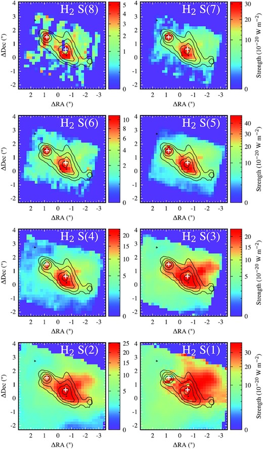
There are numerous transitions of molecular hydrogen from 5 to 17 μm. We generated maps of these emission lines in Fig. 11 where we show the S(1) to S(8) transitions. These have been corrected for extinction using the map in Fig. 4. It is worth noting that this likely leads to an overcorrection of the extinction for source A as the extinction map was inferred from silicate depth and thus measures the extinction from the continuum. As discussed in Section 4.1 the continuum of source A is more embedded and therefore using this extinction we are overcorrecting the H2 line fluxes, in particular the S(3) J= 5, 9.665 μm transition, which sits in the 9.8 μm silicate absorption band. This is seen in Fig. 11 where for S(3), source A appears relatively brighter than in the other lines which are less sensitive to the extinction correction. We therefore also show the uncorrected line maps in Fig. 15 (Appendix C).
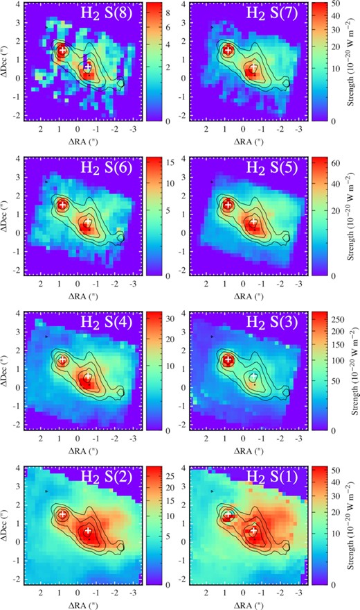
Maps of the integrated flux of the molecular Hydrogen transitions from the highest energy H2 S(8) (5.053 μm) to the lowest energy H2 S(1) (17.0 μm). The white crosses mark the continuum positions of sources A and B. These maps have been corrected by extinction using the optical depth map shown in Fig. 4. The contours show the 6.2 μm PAH emission.
Fig. 11 illustrates a clear shock with a front south of source B as suggested by the [Fe ii] emission in Fig. 10. Moving to the lower energy transitions the peak moves behind the shock front tracing the cooler gas. We also show a map of the 6.2 μm PAH emission as contours in Fig. 11 which traces regions of star formation. For most of the structure the molecular hydrogen is consistent with the PAH emission as stars are expected to form from the molecular gas and young stars excite the PAH molecules. However behind the shock front there is a clear region of molecular hydrogen which devoid of any 6.2 μm PAH emission.
Shocks are expected to destroy PAH molecules (e.g. Micelotta, Jones & Tielens 2010) where the shock heated gas produces high energy collisions (∼ 1 KeV) with the PAH molecules that destroys the smaller molecules first. Interestingly we do not see destruction of the 6.2 μm PAH band at the shock front but rather we see strong PAH emission here with the destruction behind the front where the PAH emission is lacking. A possible explanation is that the destruction is delayed such that the PAH molecules are destroyed after the shock has passed through the region in the hot post-shock gas.
4.4.1 H2 Excitation
Under the assumption of local thermodynamic equilibrium (LTE), the relative fluxes of these transitions can be modelled where the molecular hydrogen column density and temperature determine the relative population of the energy levels and thus the relative fluxes observed. We use a two temperature gas model to measure the temperature and the column density of molecular hydrogen for each component. At each spaxel we fit the hydrogen transitions using the photodissociation region toolbox code2 (Kaufman, Wolfire & Hollenbach 2006; Pound & Wolfire 2008, 2011) with the ortho-to-para ratio fixed at 3. As the S(3) transition occurs at 9.665 μm which sits in the peak of the silicate absorption, it is highly sensitive to the extinction correction and so we include this point but with a large (50 per cent) error to ensure it does not bias the fits. As the S(0) J = 2 transition lies out with the observing range of MIRI (28.21 μm), we use the anchor point from Spitzer observations (Petric et al. 2018) to act as a guide for the model to prevent non-physical solutions. To match the flux with the JWST/MIRI data we scale the S(0) flux by matching the S(1) measurement from Spitzer to the median of the S(1) map from MIRI. We give the value a 50 per cent error to account for this large uncertainty and to make it act as simply an anchor point. For the two point sources, A and B, we fit the sum of the line fluxes in a 3×3 pixel grid around the continuum position to avoid PSF effects.
In Fig. 12 we show the measured total column density of molecular hydrogen, the temperature of the cold gas component, and the temperature of the hot gas component from these fits for each spaxel. Along the shock front, there appears to be a cavity in the column density coinciding with an increased temperature in both the cold and hot gas. It is worth noting that these two quantities are somewhat degenerate from the fitting process and so should not be taken as two independent measures of the gas properties. Behind the shock the molecular hydrogen column density increases approaching |$N_{H_2} \xrightarrow {} 10^{21}$| cm−2 as the temperature drops. This is expected for a fast molecular shock where the gas behind the shock reforms (see fig. 1 of Hollenbach & McKee 1989). The H2 column densities are lower but similar (∼1021 cm−2) to those found by Saito et al. (2015) using CO observations however their value is sensitive to the αCO conversion factor used.
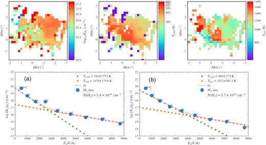
Results from modelling the S(1) to S(8) molecular hydrogen transitions. We show the total molecular hydrogen column density (left-hand panel), the temperature of the cold gas component (middle), and the hot gas component (right-hand panel). The continuum positions of sources A and B are shown with the white crosses. In the lower panels we show the fits to the two point sources A (left-hand panel) and B (right-hand panel) where each is fitted to a 3×3 region around the continuum position. In these plots the best fit is shown with the solid line composed of the cold (green) and hot (orange) gas components. These fits assume an ortho-to-para ratio of 3. The S(0) (J = 2) point for these fits is from Spitzer observations (Petric et al. 2018) and acts as a loose anchor to prevent non-physical solutions.
The lower panels of Fig. 12 show the fits for the two nuclei A (left-hand panel) and B (right-hand panel). As can be seen in these plots the S(0) (J = 2) is not predicted by the model but does act to prevent the solution from being non-physical. This suggests that with just two components the model is only able to fit the hotter gas and an additional cold component may be required to fit this transition. Adding this additional component to the model would add 2 more parameters which may be too many as the J = 2 transition is highly uncertain and therefore the constraints on this cooler component would be very weak. For source A we also see the overcorrection of the extinction where the S(3) J = 5 transition appears too high.
The temperatures we measure are high (Thot > 1000 K) as we are sensitive to the high energy transitions in the fitting. Calculating a temperature from the S(7) and S(5) fluxes (following Lambrides et al. 2019) using a 4.5 arcsec aperture from Spitzer spectral mapping data (Donnan et al. 2022), finds a temperature of 1078 K. Considering this is over a larger spatial scale and is still >1000 K, reinforces this result.
5 DISCUSSION
CONs are rare amongst all galaxy types which suggests this is a short-lived phase in galaxy evolution, however the high obscuration may hide extreme SMBH growth and/or compact starburst activity. CONs are commonplace among LIRGs and ULIRGs (Falstad et al. 2021; Donnan et al. 2022) and are prevalent in major mergers. The evolutionary picture of these objects is relatively unknown, in particular its origin and subsequent evolution. The obscured source A in VV 114E is an interesting object to study to ask this question.
Our analysis in Section 4.1 finds that the PAH EW ratios for source A are low, indicative of a buried continuum source. The decomposition model finds a nucleus that has a sufficient optical depth τN = 5.6 to reach the CON definition (Donnan et al. 2022) and pass the threshold. This object therefore may be anywhere between the start or the end of the CON phase. The lack of high ionization lines such as [Ne v] suggests if an AGN is present, the radiation field is completely obscured and unable to affect the surrounding environment. This is confirmed by looking at the imprint on the PAH molecules that the central source makes. AGNs are known to destroy PAH molecules very close to the central engine or alter their properties in the circumnuclear region (García-Bernete et al. 2022b, a) where neutral, large molecules are observed. This suggests the possibility that the hard radiation field from the AGN destroys the small molecules first and so the imprint of AGN feedback can be seen through the PAH properties.
For source A we found the 11.3/6.2 PAH flux ratio to indicate a population of ionized PAHs, typical of star-forming regions. This suggests that there may not be any AGN present or that it must be extremely obscured such that the PAHs have not affected by the AGN. The latter explanation is required to be consistent with the prediction from Saito et al. (2015) which suggested the possible presence of a hidden AGN through an elevated HCN/HCO+ ratio.
X-ray emission has been observed from this source however only upper limits have been placed on the X-ray luminosity of an intrinsic AGN (Ricci et al. 2021) with log L2−10 < 41.11 erg s−1 and log L10−24 < 40.95 erg s−1. These values are typical of CON dominated sources.
In summary, we detect a completely obscured nucleus for source A which may be a hidden AGN as suggested by Saito et al. (2015). This object therefore may be the progenitor of a quasar where the AGN is yet to influence its host galaxy, as we see no evidence for any feedback on its surroundings. Indeed ULIRGs have long been thought to be such progenitors (Sanders et al. 1988). To evolve towards an unobscured quasar requires clearing of the obscuring gas/dust which will require kinematic analysis to identify possible outflows responsible. Further study of these objects are therefore necessary to understand the possible onset of AGN feedback and how this fits in the evolution of galaxies.
From [Fe ii] emission and analysis of the transitions of molecular hydrogen, H2, we detect a shock front south of nucleus B (illustrated in Fig. 10). The origin of this shock is unclear. Our analysis suggests that source B is a compact star-forming region and so supernovae (e.g. Reach et al. 2019) or winds from massive stars (Hollenbach 1997) may be responsible if the shock originates from this region. However it appears more extended which suggests that this shock may simply be a product of the galaxy–galaxy interaction. This may form part of a larger shock, where in Fig. 1 the 7.7 μm PAH emission traces this region and extends to the west. Indeed, Saito et al. (2017) detect CH3OH emission across ∼ 3 kpc which extends between the two merging components of VV 114. They therefore suggest this is due to a large-scale shock from the galaxy–galaxy interaction. It is also interesting to note that the shock front appears very dusty as seen in Fig. 4 where the optical depth increases.
6 CONCLUSIONS
We have used spatially resolved mid-infrared spectroscopy from JWST/MIRI MRS observations to investigate the obscured environment of VV 114E. We model the spectrum from 5–28 μm within three apertures (shown in Fig. 1) from which we measured the properties of the PAH molecules. We also construct maps of various molecular and ionized lines. Our main findings are:
From the low 12.7/11.3 and 6.2/11.3 PAH EW ratios we find that source A is heavily obscured and hosts a buried nucleus. The PAH EW ratios are elevated for source B while source C is typical of star-forming regions. By decomposing the spectrum into nuclear and star forming, we measure a nuclear optical depth of τN = 5.6, which is large enough to meet the threshold required for CONs.
The 11.3/6.2 PAH flux ratios suggests an ionized population of PAHs typical of star-forming regions for all three sources.
We do not detect any high ionization potential lines such as [Ne v] or [Ne vi] which further rules out the possibility that source B is an AGN however the high obscuration of source A means a hidden AGN is consistent with this lack of high ionization lines.
We detect clear evidence of shock south of source B with elevated [Fe ii] emission. The molecular hydrogen lines trace this shock where the higher energy transitions peak at the shock front and move behind towards the lower energy transitions.
The 6.2 PAH emission does not trace the low energy H2 emission lines which suggests the ionized PAH molecules are destroyed in the post-shock gas. This may be a delayed process as the PAH emission is strong at the shock front and only subsides behind the shock.
From modelling the transitions of molecular hydrogen, we detect clear evidence of a shock front south of source B with a ridge of increased gas temperatures resulting in higher column densities behind the shock front where gas is expected to reform.
These results suggest that nucleus B is likely a star cluster while source A contains an extremely obscured nucleus. This nucleus shows typical characteristics of CONs and may be powered by an AGN. This initial analysis shows the power of the JWST for studying these highly obscured environments, where future kinematics studies are needed to understand the role of outflows in the evolution of these objects.
ACKNOWLEDGEMENTS
FRD acknowledges support from STFC through grant ST/W507726/1. DR and IGB acknowledge support from STFC through grant ST/S000488/1. DR also acknowledges support from the University of Oxford John Fell Fund. AAH acknowledges support from grant PGC2018-094671-B-I00 funded by MCIN/AEI/ 10.13039/501100011033 and by ERDF A way of making Europe, and grant PID2021-124665NB-I00. The authors are grateful to the ERS team for the observing program with a zero-exclusive-access period.
DATA AVAILABILITY
All the raw data used in this work is available through the MAST archive.3
Footnotes
REFERENCES
APPENDIX A: EXTINCTION CURVE
There are many extinction curves presented in the literature (e.g. Kemper et al. 2004; Chiar & Tielens 2006), however we found that none of these produced good fits for highly obscured objects and in particular the obscured nucleus (A) from VV 114E. We therefore created an empirically based extinction curve using a heavily obscured galaxy that has no apparent PAH emission, namely IRAS 08572+3915.
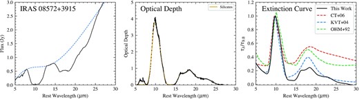
Left-hand panel: Spitzer IRS spectrum of IRAS 08572+3915 in black with the interpolated cubic spline continuum shown as the dashed blue line. Middle: Optical depth profile extracted from the log ratio of the interpolated continuum to the spectrum. The inferred silicate absorption is shown with the gold line. Right-hand panel: Extinction curve constructed from a power law + silicate template. This is compared to three popular choices from the literature (Ossenkopf et al. 1992; Kemper et al. 2004; Chiar & Tielens 2006).
APPENDIX B: MODEL FITS
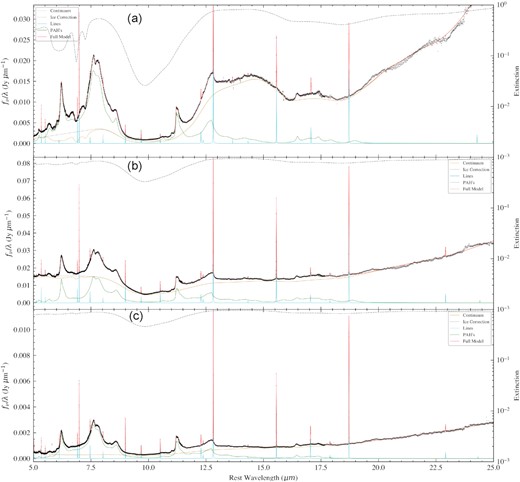
Fits to the spectra of VV 114E with our modified PAHFIT model from regions A (top), B (middle), and C (bottom) as shown in Fig. 1. The full model is shown in red with its constituent parts labelled in the legend. The right-hand axis of each plot shows the extinction factor, |$e^{-\tau _{\lambda }}$|, with the dashed black line.
APPENDIX C: Uncorrected H2 maps
Same as Fig. 11 but without any extinction correction applied.
