


ABSTRACT
The fate of organometallic dust subjected to extreme conditions, especially the shock fronts, in the interstellar medium (ISM) has not been explored to date. Iron and cyclopentadiene, which have been found to be present in the ISM, are known to react and produce the organometallic compound ferrocene under terrestrial conditions. In our experiment we subjected ferrocene, a possible proxy of such dust, to ∼5.6 Mach (M) shock commensurate with conditions encountered in the ISM, leading to a temperature rise up to 7300 K within 2 ms. Analysis of the post-shock residue showed the presence of a α-Fe and Fe3C composite that responded to an external magnetic field. These results show that a non-magnetic dust composed of molecules containing transition metals undergoing shock processing in the ISM can dissociate and synthesize dust that is then magnetic. Such drastic transformations from non-magnetic to magnetic dust induced by shocks might be of importance in interstellar polarization.
1 INTRODUCTION
It is well known now that the interstellar medium (ISM), which plays a key role in the chemical evolution of the molecular Universe, is comprised of an inhomogeneous mixture of gas (99%) and dust (1%). Over the last few decades, our view of the ISM has changed considerably. Based on the pressure, temperature, and state of the matter, the ISM can now be classified into various phases starting from very hot coronal gas regions to chemically rich molecular clouds (Tielens 2005). To date, an ever-increasing list of 270 molecules have been reported to be present in the ISM (CDMS; Müller et al. 2005). Most of the heavy elements produced in the cores of the post-evolved stars are injected into the ISM by supernova explosions or from ejecta of asymptotic giant branch (AGB) stars (Tielens 2005), and both of these processes drive shock fronts into the ISM. Later, elements from this ejecta are incorporated into the various phases of the ISM and enrich the chemical complexity of the universe.
Iron (Fe) is the most abundant heavy element that has been observed in the ISM (Anders & Grevesse 1989). Despite its ubiquitous presence in various parts of our Solar system (Asplund et al. 2009), a significant amount of iron that is expected to be present is missing in gas-phase observations both in the ISM and in the circumstellar medium (CSM) (Savage & Bohlin 1979; Lacy et al. 1989). Such depletion of iron from the gas phase suggests that it could be locked up in the form of dust. Submicron to nanometre size dust grains have been observed in various parts of the ISM as well as in our Solar system (Henning & Salama 1998; Henning 2010; Xie et al. 2018). These dust grains have been thought to be produced in the ejecta of the evolved AGB stars via gas-phase condensation processes (Gail et al. 2009; Zhukovska & Henning 2013; Gail, Scholz & Pucci 2016). Cosmic silicate dust has been considered as a possible site for sequestering iron, where it might be locked up in the form of pyroxene and olivine (Henning 2010, and references therein). However, recent studies have shown that cosmic silicates observed in the envelope of the AGB stars are iron-poor (Millar 2016). The contribution of silicate dust in the depletion of iron remains unclear. Other repositories of iron include iron sulphide which is known to be present as one of the components of dust in comets, asteroids, and Interplanetary Dust Particles (Dai & Bradley 2001). The infrared signatures of iron sulphide grains (FeS) have also been observed around the circumstellar shell of young star (Keller et al. 2002), around planetary nebula (Hony et al. 2002) and they contribute significantly to the depletion of both iron and sulphur from their gas phase. Two other molecular forms of iron are known to be present in the ISM: iron oxide FeO (Furuya et al. 2003) and iron cyanide FeCN (Zack, Halfen & Ziurys 2011). Iron might also be locked up in the form of carbides like Fe3C (Moseley 1980). The other proposed iron-bearing molecules in ISM are FeH and FeH2 (Bar-Nun, Pasternak & Barrett 1980).
Organometallics have been considered as one of the important components of interstellar (Serra et al. 1992) and cometary dust (Serra et al. 1992). In general, it is defined as [ TMnLmAro], where n, m, o are the integers and TM is any transition metal like Fe, Ni, Cr, and L is any type of ligand molecule such as a hydrocarbon chain, CO, etc., which serves as an electron source, and Ar is any aromatic molecule (Fioroni 2016). Signatures of organics are widely present at various parts of the ISM as well as in our Solar system bodies (Kwok 2011). Depending on the abundance of the organic ligand molecules and aromatics, various kinds of iron-bearing organometallic molecules have been proposed to be present in the ISM and as well as in the Solar system (Serra et al. 1992; Klotz et al. 1996). The presence of various polyynes (- C ≡ C -) n have been reported in ISM (Broten et al. 1978; Galazutdinov et al. 2001) and CSM (Souza & LUTz 1977; Hinkle, Keady & Bernath 1988; Bernath, Hinkle & Keady 1989; Fonfría et al. 2018). Iron in the form of clusters could also be attached to polyynes and form a particular class of molecule known as iron pseudocarbyne (Tarakeshwar et al. 2019). Carbonyl group can also serve as a ligand in which nascent iron could be locked up. Iron pentacarbonyl (Fe(CO)5) has also been proposed as an important component of cometary dust (Huebner 1970).
Collisions between the larger polycyclic aromatic hydrocarbons (PAHs) found in the ISM (Tielens 2008, 2013; Candian, Zhen & Tielens 2019; Li 2020) and the Solar system bodies (Moreels et al. 1994) and Fe ions in the gas phase are postulated to lead to the formation of a stable Fe-PAH complex (Serra et al. 1992). Experiments have also shown the formation of a stable organometallic cluster due to the collisions between the smaller PAHs like benzene, naphthalene, and iron cations in the gas phase (Boissel 1994; Boissel et al. 1995; Szczepanski et al. 2006). Observations from 20 different comets at various parts of our Solar system in the heliocentric distance range of 0.68 to 3.8 au have shown the presence of neutral iron and nickel atoms (Manfroid, Hutsemékers & Jehin 2021). Previously, signatures of iron were only observed in two sungrazing comets: the ‘Great Comet of 1882’ (Burke-Gaffney 1968) and in the comet ‘C/1965 SI (Ikeya- Seki)’(Thackeray et al. 1966). It has been shown (Manfroid et al. 2021) that the iron and nickel signatures were observed from those comets which were far from the sun (∼3.8 au). At this distance from Sun, the temperature of the cometary nuclei will not be sufficient to sublime any iron-containing refractory dust. Organometallic molecules have been considered as a component of cometary dust (Serra et al. 1992). Hypervelocity micro-meteorite bombardment of a cometary organometallic molecular matrix can raise temperature to few thousand Kelvin and can lead to the ejection of the metal atoms attached within it (Manfroid et al. 2021). Hence, organometallics can play a vital role in the chemical enrichment of the ISM as well as in the Solar system bodies. Owing to the importance of organometallics in astrochemistry, there is a need to carry out a series of experiments to understand their evolution under extreme conditions.
Recently, cyclopentadiene has been detected in the dark molecular cloud TMC-1 along with two other hydrocarbons viz. cyclopropenylidene and indene (Cernicharo et al. 2021). Cyclopentadiene under terrestrial conditions is known to react with iron cations in the gas phase and can make the simplest organometallic molecule ferrocene (Fe(C5H5)2) (McKee 1992). It has a sandwich-like structure in which an iron atom is trapped in between two pentagonal hydrocarbon rings (Wilkinson et al. 1952). In the ISM, the formation of any molecule depends on the energetic processing and rates of the reactions involved between the abundant elements/atoms/molecules. Reactions leading to the formation of ferrocene in space in the gas phase or mediated by solid-phase processes are not known. Also, the dipole moment of ferrocene is ‘zero’ (Mohammadi et al. 2012). It cannot be detected using sub-mm observations. Considering all the factors discussed in this paragraph, we contemplate ferrocene as a proxy of organometallic dust in ISM.
Ferrocene was first discovered in the laboratory in the 1950s; ferrocene-based molecules have an enormous impact on organometallic chemistry due to their involvement in catalytic reactions, charge transfer processes, and polymer reactions (Heinze & Lang 2013). In nanotechnology, ferrocene has been used as a catalyst and a source of carbon for the growth of carbon nanostructures (Barreiro et al. 2006; Moisala et al. 2006). Photoprocessing followed by heating of ferrocene has been shown to form iron-bearing carbon nanostructures (Elihn et al. 2007). High-pressure (8 GPa) and high-temperature (500 to 1200 K) processing of ferrocene has also been shown to result in the formation of iron-carbide nanostructures (Davydov et al. 2014; Baskakov et al. 2018). However, despite its importance in terrestrial organometallic chemistry, the role of ferrocene in organometallic astrochemistry has received little attention.
Dust in the ISM is subject to both non-energetic (thermal chemistry and atom addition chemistry) and energetic processing (shock chemistry, photochemistry, radiation chemistry) (Arumainayagam et al. 2019). In nature, shock waves are created when a disturbance propagates through a fluid medium faster than the velocity of sound in that medium. The energy associated with low-velocity shock waves (<10 M) can dissociate chemical bonds and chemically enrich the propagating medium (Rudnitskij 1997). Stars are the ISMs main sources of shock waves (McKee & Hollenbach 1980). Strong stellar winds excite and ionize part of their surroundings and create a rapid pressure gradient in their neutral surroundings thereby generating shock waves (Spitzer Jr 1978). The other known sources of shock waves in ISM are supernova explosions, cloud–cloud collisions, and expansion of H ii regions (Spitzer Jr 1978). These high-velocity shock waves lead to the destruction of the dust in the ISM through various physical processes including sputtering, ionization, and grain-charging (Jones, Tielens & Hollenbach 1996), ultimately leading towards elemental recycling. However, the processing of dust in the collision-induced low-velocity shock waves (∼few km s−1) has not been well understood as compared to their high-velocity shock-processed counterparts (Arumainayagam et al. 2019).
In this work, we have explored the low-velocity (1–2 km s−1) shock processing of ferrocene powder. A shock tube has been used to mimic the conditions in extreme ISM shocks (Biennier et al. 2017; Singh et al.2020). The precursor ferrocene powder was exposed to the shock waves of ∼5.6 M for 2 ms during which the estimated reflected shock temperature was raised to ∼7300 K. Post-shock solid residues were collected and investigated using Raman spectroscopy and High Resolution-Transmission Electron Microscope (HR-TEM), Infrared (IR)Spectroscopy, Vibrating Sample Magnetometer (VSM), and XRD analysis.
2 EXPERIMENTAL METHODOLOGY
The High-Intensity Shock tube for Astrochemistry (HISTA) was used for the shock processing of ferrocene. A schematic diagram of the complete set of HISTA is shown in Fig. 1. It is a 7 m long gas-driven shock tube that has two different sections separated by a metal (Aluminium) diaphragm. The high-pressure (driver) section is 2 m long, whereas the low-pressure (driven) section is 5 m long. Both ends of the HISTA are usually closed using thick metal (steel) flanges, serving as a shock reflector and shock absorber. After thoroughly cleaning the inner walls of HISTA using ethanol (C2H5OH) to minimize any chance of contamination from the chemicals used in previous experiments, about 0.1 g of the ferrocene (purity 98 per cent; Sigma Aldrich) sample was placed at the end of the driven section and spread out radially on the inner surface of the tube. Immediately afterwards the metal end flanges at both ends of HISTA were closed and the shock tube was pumped down to the order of 10 −2 m bar. Following this the driven section was filled with UHP argon (Ar) at 0.1 bar. The Al diaphragm, which separates the driven section from the driver section, has a crucial role in the generation of shock waves. These Al diaphragms have different grove depth, with a particular grove depth being selected to achieve the required shock strength and reflected shock temperature. Since we aim to generate a very high temperature in the present experiment we used an Al diaphragm with the minimum groove depth (0.5 mm). High-pressure He at around 68 bar is filled in the driver section, which ultimately leads to the rupture of the Al diaphragm. As the diaphragm ruptures, the high-pressure He rushes to the driven section containing low-pressure Ar. This high-pressure gradient manifests itself in the form of shock waves which propagate through the driven section at a speed greater than the speed of sound. Two PCB PIEZOTRONICS dynamic-pressure sensors (Voltage sensitivity 0.4949 mV/PSI, Bias voltage 10.71 V) are positioned at the end of the driven section. Their separation is around 30 cm and they are connected to a digital storage oscilloscope. The velocity of the shock wave in the driven section can be determined by measuring the time delay in the recorded pressure signal (Fig. 2). A shock velocity of ∼1.8 km s−1 or 5.6 Mach were obtained while processing the ferrocene samples. Utilizing the shock Mach number and the Rankine–Hugoniot jump equations (Gaydon & Hurle 1963), we determined two very important thermodynamic parameters viz. the reflected shock temperature (T5) and the reflected shock pressure (P5). Using these measurements, we estimated that the sample would have experienced peak pressures around 25 bar (P 5) for about 2 ms, while the estimated reflected shock temperature (T5) of the argon gas rose to around 7300 K. The acquired and recorded pressure sensor response curve is shown in Fig. 2. A detailed explanation of the procedure used for the measurement of shock parameters has been described in recent papers (Singh et al. 2020; Surendra et al. 2021).
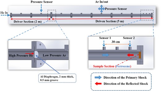
A schematic diagram of an experimental apparatus using HISTA at the Physical Research Laboratory (PRL), Ahmedabad. The driver section is initially filled with high-pressure helium (He) and the driven section is with low-pressure argon (Ar). The sample is loaded at the end of the shock tube as shown in yellow. Two Piezo electric dynamic-pressure sensors are located at the end of the driven section marked as Sensor 1 and Sensor 2 and are positioned at 30 cm apart to measure the speed of the shock.
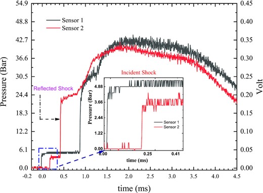
The response curve from two Piezo Electric pressure sensors placed at the end of the shock tube indicating the arrival of the incident (inset) and reflected shock as recorded using a digital storage oscilloscope.
High intensity shocks may induce physico-chemical changes in the sample and it is very likely that a significant amount of the powder sample would have transformed into the gas phase after the processing. To avoid any loss of processed sample, we left the entire shocked gas for a couple of hours to allow residue to settel inside the shock tube. During the settle down period, the internal static pressure of HISTA was around 18 bar; we then slowly removed the shocked gas to the atmosphere using a leak valve. While doing this we allow the shocked gas to pass through a Teflon filter where sub-micron-sized processed particles were trapped. Once the shock tube’s internal pressure becomes equal to the atmospheric pressure, we opened the end flange of the driven section and collected the rest of the processed samples in the vicinity to the end flange area. The amount of processed sample collected was approximately 30 per cent of the original mass. Therefore, a significant amount of sample was lost while removing the shock-processed gas.
The collected solid samples were then examined under ambient conditions using different experimental techniques including X-Ray Diffraction (XRD), Raman Spectroscopy, and HR-TEM imaging, IR and VSM. We used a D8 DISCOVER (Bruker) powder X-ray Diffractometer with Cu K α radiation source to record XRD patterns. Raman analysis was performed by placing samples on a glass plate and then exciting them using 532 nm wavelength Laser. For the HR-TEM imaging, we used a Thermo Fisher Transmission Electron Microscope, in which the images were recorded using a 300 kV operating voltage. Interplanar spacing of lattices fringes were calculated using imagej (Abràmoff, Magalhães & Ram 2004) software.
3 RESULTS AND DISCUSSION
3.1 XRD analysis
The XRD pattern of ferrocene is shown in Fig. 3(a), we can observe all of the intense peaks within the small-angle value of 2θ ∼ 10°–30°. This indicates that the patterns originated due to X-ray diffraction from the planes with larger inter-planar spacing. From the crystallography, it is known that ferrocene molecular crystal belongs to P21/a space group and it has a monoclinic unit cell with lattice parameter, a = 9.00 Å, b = 7.52 Å, c = 5.94 Å, β = 92.5° (Eiland & Pepinsky 1952). In the work by Baskakov et al. (2018), they observed a broad low-intensity pattern of ferrocene around 45 º. In our XRD pattern, such a feature is missing. A possible reason for this was the X-Ray source used in our analysis. We used the Cu K α radiation source, which produces X-ray fluorescence while interacting with iron-based systems (Klug & Alexander 1974; Mos et al. 2018). Baskakov et al. (2018) used a Co K α radiation source to record the XRD pattern. Co K α does not produce fluorescence emission while interacting with iron-based materials (Klug & Alexander 1974; Mos et al. 2018). That is the reason, in our case, the low-intensity peak of ferrocene around 45º could be suppressed because of the presence of fluorescence.

The XRD pattern of the ferrocene is shown in Fig.3(a), and in Fig. 3(b) the XRD pattern of the shock-processed (5.6 M, 7300 K) sample is shown. The blue arrows show the presence of Fe-Fe3C composite, the black circle indicates the graphite-like carbon feature, and the stars show the presence of Al in the shock-processed sample.
Fig. 3(b) shows the XRD pattern of the shock-processed (5.6 M, 7300 K) sample which was smoothed using the S-G method with a second-order polynomial, and a smoothing window of 25. There are very well-separated peaks in the 2θ ∼ 30°–70°. The peaks marked by blue arrows are assigned to the Fe-Fe3C composite (JCPDS Card Files, No. 89–2867, (Bagramov et al. 2012; Baskakov et al. 2018), where the most intense peak is around 43.5° and the peak around 64° are two well-recognized peaks of α-Fe. A few low-intensity peaks of iron carbide can be seen around the intense peak, about 43.5º, marked by blue arrows. α-Fe is the most stable form amongst the allotropes of iron. Features of Fe3C, including the low-intensity peaks, which we observe as shoulder peaks, are quite prominent in the XRD pattern shown by Baskakov et al. (2018). This again is because of different types of X-ray source (high back ground in our case) used by us. The crystallinity of iron carbide produced by Baskakov et al. (2018) is better, which contributes to differences in the XRD pattern (formation pathway used by them is different from ours). Here, our objective was not to produce good quality iron carbide; instead, our interest lies in understanding the evolution of the organometallic dust analogue ferrocene induced by the low-velocity ISM like shock produced in the lab. From the crystallographic point of view, Fe3C, known as cementite, belongs to the Pnma space group, and has an orthorhombic unit cell with the parameters a = 5.059 Å, b = 6.07 Å, and c = 4.500 Å (Baskakov et al. 2018). In our sample, the broad pattern around 26°, marked by a black circle, indicates the possible presence of carbon (JCPDS Card Files, No. 75–1621) having different degrees of graphitization . In the work by Baskakov et al. (2018) they observed a sharp peak around 30º, which they assigned to graphite (002). The peaks around 38.3°, 44.6°, and 64° indicate the presence of Al in the shock-processed sample, which originates from the rupture of the Al diaphragm. Hence, from XRD analysis, it is clear that shock-processed ferrocene changed to carbon and iron carbide composite systems.
3.2 Raman spectroscopy
Raman spectra of the pristine ferrocene (marked as black) and its shock-processed counterpart are shown in Fig. 4. From the symmetry of the molecule, it is known that ferrocene has 15 Raman active vibration modes (Bodeniheimer et al.1969) and are either inter-ring or intra-ring vibrations. In Fig. 4, we can see that a doublet appears around 350 cm−1. This feature corresponds to the inter-ring vibrational motion, where the most intense peak is around 314 cm−1 due to the symmetric ring metal stretching mode (Long & Huege 1968). The relatively less intense doublet around 395 cm−1 represents the symmetric tilt of the ring (Long & Huege 1968). The peak around 1074 cm−1 is due to the –CH bending motion (Long & Huege 1968). The strong spectral feature around 1116 cm−1 is due to the symmetric ring breathing motion (Long & Huege 1968). A relatively less intense peak is seen around 1424 cm−1, which is assigned to the symmetric stretching vibration of carbon atoms in the ring (Long & Huege 1968). The intense spectral feature around 3130 cm−1 is due to the –CH symmetric stretching motion (Long & Huege 1968).
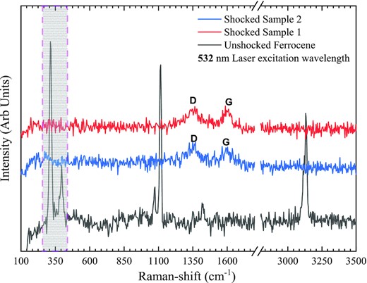
Raman spectra of the pristine ferrocene and the shock-processed sample. We used a 532 nm laser excitation wavelength. The shaded region around 350 cm−1 is the signature of ring-metal and ring tilt vibrational modes present in ferrocene but absent in the shocked sample. Both spectra from different positions of a shocked sample have the same spectral features with broad D and G bands.
In Fig. 4, we also show two Raman spectra of the shock-processed sample recorded at two different places in the same sample. These spectra have the same features and fewer bands than their unshocked counterparts. Two broad spectral features exist, around 1348 cm−1 and about 1593 cm−1. The broad-band around 1348 cm−1 is known as the D band. This band appears due to the defect present in the carbon system. The broad-band around 1593 cm−1 is designated as the G band. This G band corresponds to the in-plane vibration of the sample's sp2 bonded (graphite-like) carbon atoms. We can compare our Raman spectra with the single-phase Fe3C Raman spectra obtained by Zhang et al. (2015). In their ranges, the D band is around 1350 cm−1 and the G band is about 1590 cm−1, which is in very good agreement with our results, where D band is about 1348 cm−1, and the G band is around 1593 cm−1. These observations are consistent with our XRD results. The formation of α-Fe and Fe3C composites could be a direct consequence of the shock-induced bond destruction as the signature of the various bonds present in the unshocked ferrocene is absent in the shocked sample. The destruction of the metal-ring bond might liberate Fe from the ferrocene, whereas the destruction of other bonds, such as the C-H, releases carbon (C) and hydrogen (H) atoms to the gas phase, where the C atoms later combine with iron to form iron carbide composites. The G-band position suggests that the graphite-like carbon present in our shocked sample could be nano-crystalline graphite (Ferrari & Robertson 2004). From Raman spectra of the shocked sample, it is difficult to conclude the morphology of the nanostructure in the sample. To obtain structural information of the shock-processed sample on the nm scale, we used HR-TEM imaging.
3.3 HR-TEM imaging
HR-TEM images of the shock-processed samples are shown in Fig. 5. Fig. 5(a) shows the bright field image of the shock-processed sample, whereas Fig. 5(b–d) shows high-resolution images of the processed sample. The energy-dispersive X-ray (EDX) spectra of the processed sample used for elemental analysis are shown in Fig. 5(e), indicating that most of the nanostructures in the sample are made of carbon and iron. In Fig. 5(b), we see evidence of iron carbide nano-sheets. In Fig. 5(c), we can see carbon nanoribbons with various degrees of graphitization (marked by red arrows) attached with iron matrices (marked by blue arrows). There is also a lot of free amorphous carbon, marked by saffron-coloured arrows. Fig. 5(d) shows the presence of an iron-encapsulated carbide nanostructure which has a compact iron core (d-spacing ∼2.1 Å) of diameter ∼10 nm, and is surrounded by the onions like carbon shells (d-spacing ∼3.4 Å) with thickness of ∼4 nm.
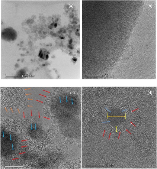
HR-TEM images (a -d) and EDX (e) spectra of the shock-processed samples with different scales.

EDX spectra of the shocked sample.(Continued.)
XRD and Raman spectroscopic observations have provided the possibility of iron carbide and free graphite-like carbon being present in the shock-processed sample. HR-TEM images and EDX spectroscopy of the shock-processed sample support these conclusions. From the EDX spectra, we could not find any trace of the presence of Al in the sample whose presence was observed in the XRD results. This means the contribution of Al, if any, in forming nanostructure as an impurity is negligible.
3.4 Infrared spectroscopy
Attenuated Total Reflectance (ATR) mid-infrared spectra of both pre- and post-shocked samples were collected at room temperature using a Nicolet IS 50 FTIR Spectrometer. During the spectra collection, we set the resolution of the spectrometer at 2 cm−1 and the average scanning period was around 1.26 min. The spectra of both pre- and post-shocked samples are shown in Fig. 6. For the unshocked ferrocene, we can see multiple prominent peaks around 3.2, 7.10, 9.05, 10, 12.31, 12.69, 20.57, and at 21.2 μm. These are very well-known IR features of ferrocene (Lippincott & Nelson 1958). However for the shock-processed sample, its IR spectra remain featureless. This shows that almost all of the ferrocene sample was converted to iron carbide–carbon composite. This observation is also consistent with Raman and XRD results which reveal that ferrocene turned to iron carbide composites and graphite like carbon is confirmed by G and D bands appeared in Raman spectra after shock processing.
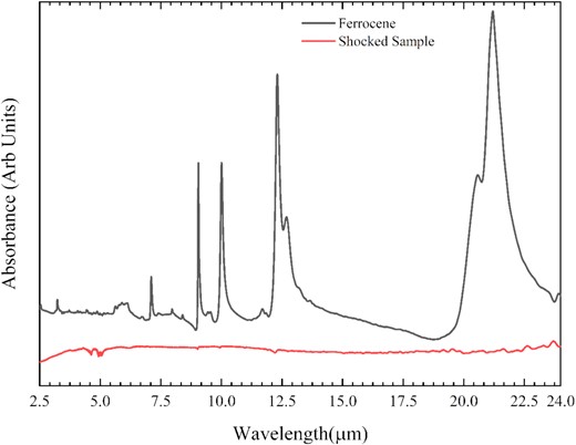
ATR-FTIR spectra of the solid ferrocene and the shocked sample at room temperature.
3.5 Magnetic response
We have studied the magnetic response of both shocked and unshocked samples. Initially, the magnetic response of the ferrocene sample before and after the shock was observed by video recording in the presence of a bar magnet (c.f. Supplementary video 1). It was observed that the initial ferrocene samples did not respond to the magnetic field because of its diamagnetic nature, whereas shock-processed residue of ferrocene showed a strong response. In order to quantify the magnetic properties of the shocked sample, we used a VSM. About 30 mg of shocked sample was placed in the VSM to obtain the magnetic properties at room temperature. The response of the shocked sample in an external magnetic field up to 2 T or 20 000 Oe has been traced as a hysteresis loop, as shown in Fig. 7; the results are typical of a sample demonstrating ferromagnetism. The measured parameters associated with a ferromagnetic sample such as Saturation Magnetization (Ms), Remnant magnetization (MR), and Coercivity (Hc) are listed in Table 1.
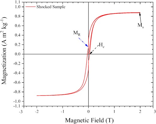
The magnetization curve of the shocked sample was recorded using a VSM (see the text for details).
Magnetic properties of the shocked sample.
| Parameters | Values |
|---|---|
| Saturation magnetization (Ms) | 0.887 A m2 kg−1 |
| Remnant magnetization (MR) | 0.154 A m2 kg−1 |
| Coercivity (Hc) | 423 × 10−4 T |
| Parameters | Values |
|---|---|
| Saturation magnetization (Ms) | 0.887 A m2 kg−1 |
| Remnant magnetization (MR) | 0.154 A m2 kg−1 |
| Coercivity (Hc) | 423 × 10−4 T |
This response curve (Fig. 7) supports the conclusions based on the results obtained from XRD, HRTEM imaging, and the Raman spectra showing the possible presence of iron carbide systems, which are known to show ferromagnetic behaviour (Sajitha et al. 2004). A finite area of our hysteresis loop indicates that our sample has no superparamagnetic constituents, as superparamagnetic particles do not have any coercivity (Huber 2005). Iron contributes most to the magnetization of the iron carbide systems. Its presence can be seen in the EDX spectra in Fig. 5(e). The magnetic properties of the iron nanoparticles can be influenced by its chemical surroundings (Huber 2005). It has been reported (Sajitha et al. 2004, 2007; Wu et al. 2011; Wang et al. 2017) that wrapping of carbon on iron or iron carbide nanoparticle leads to the reduction of saturation magnetization. In our shocked sample, the major product is carbon. HR-TEM images of our shocked sample showed the presence of carbon-encapsulated iron nanoparticles (Fig. 5c, d), where surface reactions with iron and carbon atoms might have taken place. Any bond made due to the interaction via the d orbital has a directional dependency. So when an iron atom at the surface of an iron nanoparticle makes any bond with any other atoms or molecules, it leads to the freezing of its spins in a particular direction. Thus when an external magnetic field is applied to that system, those atoms will not be able to orient their spins towards the field direction and ultimately reduce the magnetization (Huber 2005). Also, low iron carbide content in the shocked sample can be another reason for low saturation magnetization for our shocked sample. Very low saturation magnetization and high coercivity of our sample as compared to the iron carbide sample prepared from ferrocene (Sajitha et al. 2004, 2007), indicates that we produce a hard ferromagnetic iron carbide–carbon composite using shock processing.
In the shock tube, the processing time is limited; in our system, it is around 2 ms. So, the reflected shock pressure and temperature play a vital role in the conversion from the reactant to the product. The conversion rate from the reactant to the product in the shock tube varies with the processing temperature (Bhaskaran & Roth 2002). Ferrocene’s vapour pressure is 1.296 Pa at room temperature (Monte et al. 2006), and it will start sublimating during the arrival of the incident shock front, which raises the temperature to around 2000 K; later it is also processed to the elevated reflected shock temperature (around 7300 K). The conversion process can be tracked using the optical technique suggested by Sommer et al. (1996) and the references therein. In our experimental set-up, we did not employ any optical measurement system, so any in situ measurement related to the efficiency of the entire conversion process is difficult to calculate. However, we tried to understand the conversion using XRD, IR, and Raman spectroscopic techniques. From those analyses, we can conclude that shock processing of ferrocene leads to formation of iron carbide–carbon composites, which have an iron core of 10 nm and are surrounded by onion-like carbon shells of around 4 nm. The carbon shell around the iron nanoparticles provides better stabilization of its magnetic property by minimizing the flipping of the magnetic moments caused by thermal fluctuations (Wu et al. 2011). This structure also acts as anti-oxidation layer to the iron core and enhances its chemical stability (Wu et al. 2011). We also observe the presence of carbon nanoribbons, an iron carbide nano-sheet, and amorphous carbon in the shock-processed sample. Previously, these kinds of structures were synthesized from ferrocene at very high pressures and temperatures (8 GPa, 500–1220 K) and exposures of 20 s in each temperature zone (Davydov et al. 2012; Baskakov et al. 2018). These experiments have shown the transformation of amorphous iron carbide composite to its crystalline form Fe7C3 and then its transformation to crystalline Fe3C with the isobaric stepwise increment of temperature. However, in our experiment ferrocene was subjected to an intense shock (5.6 M) for 2 ms resulting in a reflected shock temperature of up to 7300 K. Hence, the shocked dust samples are the product of ultra-fast (2 ms) thermal processing from room temperature to ∼7300 K at the rate of ∼106 K s−1, compared to the multistep formation pathway showed by Davydov et al.(2012) and Baskakov et al. (2018) by thermally processing the sample up to ∼2000 K by slow heating rate using a toroidal high-pressure cell in a graphite heater.
Elihn et al. (2007) have shown the formation of iron carbide composite using 193 nm, 15 ns pulse duration ArF excimer laser ablation. To understand the shock-induced thermal decomposition of ferrocene, we can refer to the molecular dynamics simulations and DFT calculations obtained by Elihn & Larsson (2004). According to these DFT calculations the energies of various bonds present in ferrocene are 492 kJ mol−1 (C-H), 602 kJ mol−1 (C-C), and 1480 kJ mol−1 (Fe-C ring). Hence, in high-intensity shocks, we can expect a sequence of bond breaking resulting in the decomposition of ferrocene. First, at 2000 K, the C-H bonds will break apart and release hydrogen into the gas phase. A lot of carbon will be released due to the destruction of C-C bonds in the rings and then, later, the metal ring bonds will break and release iron. The entire process can take place within 300 fs (Elihn & Larsson 2004), much faster than our experimental shock exposure time-scale (2 ms). The carbon produced due to the destruction of C-C bonds should be placed into the vapour phase during the shock wave exposure (Bundy 1989) but when the temperature drops below 4000 K the carbon present in the vapour will start to nucleate (Bundy 1989) to form the complex carbon nanostructures, as seen in Fig. 5. Nucleation of carbon from its shock-processed vapour phase can give rise to different carbon nanostructures starting from carbon nanoribbons to fullerene, carbon nanotubes to graphene (Roy et al. 2022), where carbon nanoribbons are the most dominant component. Here, in our TEM images in Fig. 5, we observed the presence of carbon nanoribbons, carbon nano sheets, and amorphous carbon too. The role of iron as catalyst during the growth of carbon nano structure cannot be ignored. The presence of graphitic shells around iron nanoparticle as shown in Fig. 5(d) can be the consequences of metal-mediated crystallization process (Ramirez et al. 1999).
The results obtained in this experiment have some implications for dust recycling in the ISM. Dust throughout its life cycle moves back and forth in various forms and phases (Jones 2004). This experiment shows that shock processing of the organometallic dust analogue, ferrocene, results in the formation of Fe–Fe3C composites and graphite-like carbon. Iron carbide composites have been considered as a component of ISM dust (Moseley 1980). The presence of Fe3C in the shock-processed sample is therefore an indication of a possible transformation pathway from one phase of dust to another phase. We also have α-Fe and the amorphous carbon in the shock-processed sample. This is a clear indication of shock-induced elemental recycling in the ISM. From our experiments, it is also clear that organometallics not only play a role as a catalyst but it can also serve as a source of carbon during the growth of carbon dust in ISM.
Apart from the extinction of background starlight, dust present in ISM can also manifest itself through its ability to polarize incident light. The well-accepted reason for interstellar polarization is the collective alignment of elongated dust grains along a particular direction (Shapiro 1975). This can be either magnetic alignment or radiative alignment (Krügel 2002). Various iron-bearing molecules starting from iron oxides sulphides (Draine & Lazarian 1999; Draine & Hensley 2013) and hydrides (Bilalbegović et al. 2017) have been proposed as a potential candidate for magnetic dust. These kinds of dust can orient themselves along the galactic magnetic field lines and could contribute to interstellar polarization. In our experiment, we have shown shock-induced transformation from diamagnetic ferrocene to ferromagnetic iron carbide composites. This implies that if organometallics, like ferrocene, present in ISM are exposed to the shock conditions, they produce iron-bearing ferromagnetic composites which can then orient themselves and so contribute to the interstellar polarization.
4 CONCLUSIONS
Ferrocene, as a proxy of organometallic dust in the ISM, was subjected to high-intensity shocks (∼5.6 M, estimated ∼7300 K). Analysis of the post-shocked samples reveals the presence of α-Fe and Fe3C composites along with graphite like carbon. Nanostructures containing carbon and iron were also observed, such as carbon nanoribbons and carbon-encapsulated iron nanoparticles. Our results show that organometallics like ferrocene can contribute to the formation of carbon nanostructures in shock-processed regions of the ISM and CSM. In addition, we observed the shock-induced transformation of an organometallic diamagnetic dust analogue (ferrocene) to α-Fe and Fe3C that are magnetic. Dust with magnetic properties are known to play a significant role in the polarization of starlight due to their alignment towards galactic magnetic field lines. Our results also suggest that a sudden change in the magnetic properties of the dust particles may be brought about by shock fronts and may contribute to a dynamic change in the polarization of light in the ISM.
ACKNOWLEDGEMENTS
AR, SV, JK, RR, PJ, AB, and BS would like to thank PRL (Dept of Space, Govt of India) for the support. AR, VS, and BS thanks the Sir John and Lady Mason Academic Trust (UK). AR was a Senior Research Fellow when this work was carried out. AB acknowledge the J.C Bose fellowship. JP acknowledges the INSA Senior Scientist fellowship. AR, VS, JKM, RR, AG, VJ, TV, and BS acknowledges the support from IIT-Gandhinagar for access to the electron microscopy, and XRD analysis facilities. AR, VS, JKM, RR, AB, BS acknowledge USIC, Alagappa University, India for providing VSM facility. The authors thank Rohit Kumar Padonia, ITI Trainee (PRL) for his help in setting up and running the shock experiments.
5 DATA AVAILABILITY
The complete set of data will be made available on reasonable request to the corresponding author(s).
