


ABSTRACT
Numerical simulations with varying realism indicate an emergent principle−multiphase condensation and large cavity power occur when the ratio of the cooling time to the free-fall time (tcool/tff) falls below a threshold value close to 10. Observations indeed show cool-core signatures when this ratio falls below 20–30, but the prevalence of cores with tcool/tff ratio below 10 is rare as compared to simulations. In X-ray observations, we obtain projected spectra from which we have to infer radial gas density and temperature profiles. Using idealized models of X-ray cavities and multiphase gas in the core and 3D hydro jet-ICM simulations, we quantify the biases introduced by deprojection based on the assumption of spherical symmetry in determining tcool/tff. We show that while the used methods are able to recover the tcool/tff ratio for relaxed clusters, they have an uncertainty of a factor of 2−3 in systems containing large cavities (≳ 20 kpc). We also show that the mass estimates from these methods, in the absence of X-ray spectra close to the virial radius, suffer from a degeneracy between the virial mass (M200) and the concentration parameter (c) in the form of M200c2 ≈ constant. Additionally, the lack of soft-X-ray (≲ 0.5 keV) coverage and poor spatial resolution makes us overestimate min(tcool/tff) by a factor of few in clusters with min(tcool/tff) ≲ 5. This bias can largely explain the lack of cool-core clusters with min(tcool/tff) ≲ 5.
1 INTRODUCTION
Multiwavelength observations (e.g. Peterson et al. 2003; Cavagnolo et al. 2008; O’Dea et al. 2008; Rafferty, McNamara & Nulsen 2008) and numerical simulations (e.g. Gaspari, Ruszkowski & Sharma 2012; Sharma et al. 2012; Li et al. 2015; Prasad, Sharma & Babul 2015) have led to a consensus picture of the physics of cool cluster cores. The radio bubbles blown by the active galactic nucleus (AGN) jets powered by accretion on to the central supermassive black hole (SMBH) carve out cavities in X-rays and inject power in the intracluster medium (ICM) comparable to the radiative losses in the core (Churazov et al. 2002; Bîrzan et al. 2004). Thus, the cluster core is in rough thermal balance, and the presence of cold gas can most naturally be understood as a consequence of the non-linear saturation of local thermal instability in presence of gravity and uplift due to AGN jets. For small density perturbations, cold gas condenses out of the hot ICM if the ratio of the background cooling time to the free-fall time (tcool/tff) is smaller than a threshold close to 10 (Sharma et al. 2012; Choudhury & Sharma 2016). For larger tcool/tff, only small density/temperature perturbations and internal gravity waves are produced (McCourt et al. 2012; Voit et al. 2017). But non-linear density perturbations and uplift by jets can produce multiphase gas even for larger tcool/tff (McNamara et al. 2016; Choudhury, Sharma & Quataert 2019).
The idealized simulations with heating and cooling balanced in shells are too idealized to compare with observations in detail but provide a useful physical framework of local thermal instability in presence of global thermal balance and background gravity. The biggest shortcomings of this model are the absence of angular momentum and strict thermal balance. Realistic simulations with AGN jets tied to cooling/accretion rate at the centre (dominated by the gas in the cold phase) show departure from a perfect thermal balance in the form of cooling and heating cycles (Li et al. 2015; Prasad et al. 2015). Also, because of the small angular momentum imparted by jets, the condensing cold gas has non-zero angular momentum and most of the cold gas circularizes at a radius ∼ 1 kpc, much larger than the SMBH sphere of influence. Thus, the question of angular momentum transport and the eventual accretion on to the SMBH, which is crucial for feedback heating, calls for closer scrutiny (e.g. see Hobbs et al. 2011; Gaspari, Ruszkowski & Oh 2013; Prasad, Sharma & Babul 2017).
Recent observations (Hogan et al. 2017; Pulido et al. 2018) have very carefully mapped out the gravitating mass distribution in galaxy cluster cores, particularly including the contribution of the brightest central galaxy (BCG) typically found at the centres of relaxed clusters. Accurate determination of the gravitational acceleration (g), and hence tff ≡ (2r/g)1/2, profile is crucial in testing the tcool/tff models. Earlier models (e.g. Voit & Donahue 2015; Lakhchaura, Saini & Sharma 2016) were not as accurate in calculating the tff profile close to the centre (where tcool/tff is minimum). The key advantage of the Hogan et al. (2017) and Pulido et al. (2018) models is that they fix the central potential to be that of an isothermal sphere commensurate with the stellar mass of the central BCG. In other methods, where either only the dark matter halo potential is used or where a parametric form of the potential is not assumed, imposing hydrostatic equilibrium (HSE) can underestimate gravitational acceleration. Additionally, Hogan et al. (2017) find that the number of observed clusters below tcool/tff ≲ 10 is significantly lower than what was found in the numerical simulations (e.g. Li et al. 2015; Prasad, Sharma & Babul 2018), implying that the real clusters are not cooling as much as in simulations. There could be several possible reasons for such a discrepancy including, but not limited to, some missing physics in the simulations and biases in interpreting the observed spectra. We require detailed analysis of these possibilities to reconcile this discrepancy.
In this paper, we explore the effect of observational biases in interpreting non-hydrostatic atmospheres and realistic simulations. We use different density and temperature distributions – ranging from smooth profiles in hydrostatic equilibrium to very disturbed ICM in jet-ICM simulations – to quantify biases introduced by spectral deprojection and different methods to obtain tff profiles. We use the mock projected spectra and compare the methods of Hogan et al. (2017, hereafter H17) and Lakhchaura et al. (2016, hereafter L16) in recovering the input tcool/tff profiles. We also use the data from realistic simulations (Prasad et al. 2015) that include AGN feedback to compare the true tcool/tff profiles against the recovered tcool/tff profiles using the observational/analysis techniques. We also compare methods used by L16 and H17 to recover the tcool/tff profiles and point out their strengths and weaknesses in each of the cases.
This paper is organized as follows. We describe our methods of creating projected spectra from a number of theoretical atmospheres in Section 2. Section 3 describes the results of our experiments in each case and provides an overall understanding of biases in recovering tcool and tff. We discuss the implications of our results in Section 4. We finally present our conclusions in Section 5.
2 METHOD
In this paper, we wish to generate mock projected X-ray spectra from theoretical/simulated ICM models and to understand the biases introduced by various assumptions. This is done in four steps. First, projected surface brightness maps and spectra are obtained for a given theoretical/simulated model using a software package called pass (Sarkar, Nath & Sharma 2017) assuming apec plasma emission model. The spectra are then divided into different annuli so that each annulus contains a minimum number of counts. Next, we find the average spectrum for each annulus, which is then fitted and deprojected to obtain a radial profile for the electron density and temperature. Finally, the cluster gravitational models and other quantities are reconstructed using these density and temperature profiles. Below we describe these procedures one by one.
2.1 Models
To understand the biases, we consider a variety of toy models as well as realistic simulation data of galaxy clusters. Below we describe each of these models.
2.1.1 Spherically symmetric toy models
We considered two type of models where the min(tcool/tff) ≈12 and min(tcool/tff) ≈5. The minimum values were obtained by adjusting the parameter K0 (the core entropy; 10 and 2 keV cm2 for the two cases, respectively) in the setup described above. We use these models to test our projection-deprojection tool as well as use them as the default ICM models on which different non-hydrostatic components are added.
2.1.2 Cavity models
Clusters are generally believed to host X-ray cavities, thanks to the activity of an AGN at the BCG. Depending on the accretion rate, orientation, and precession of the AGN, the cavities can be of different shapes and sizes. The cavities are believed to be hot but of low density and therefore they appear to be devoid of any X-ray emission. To take into account these effects, we consider a range of simplistic cavity models where the X-ray emission was manually set to be zero inside the spherically symmetric hydrostatic gas distribution:
Spherical: These cavities consist of two spherical empty regions, each of radius r0 and put at z = ±r0 to represent hot bubbles rising from the central BCG but has not yet disconnected from the centre.
Displaced spherical: It is also possible that the AGN has shut off in the recent past leaving behind cavities that have risen up due to buoyancy and lost contact from the centre. To mimic such situations, we consider two spherical cavities of radius r0 centred at (0, 0, ±z0).
Conical: These are two conical (right circular) shaped cavities, the symmetry axis of which is lying along the z-axis with the apex being at (0,0,0). These cavities are characterized by their height hcav and half-opening angle θcav.
Detailed values of r0, z0, hcav, and θcav in different models can be found in Table 1. An illustration of the cavity models is also shown in Fig. 1.

Cartoon diagram of different cavity models considered – (panel a) spherical cavity models, (panel b) conical cavity model, and (panel c) displaced spherical cavity model. The symbols contain the same meaning as in Table 1.
Parameters used in the test models and simulations.
| Model name | Description | Values |
|---|---|---|
| sc1a | Spherical cavity with radius r0 and placed at z = ±r0; min(tcool/tff) ≈12 | r0 = 10 kpc |
| sc2a | ” | r0 = 20 kpc |
| sc3a | ” | r0 = 40 kpc |
| cc1a | Conical cavity with half-opening angle θcav and height hcav; min(tcool/tff) ≈12 | hcav = 10 kpc, θcav = 30° |
| cc2a | ” | hcav = 20 kpc, θcav = 30° |
| cc3a | ” | hcav = 20 kpc, θcav = 45°, θview = 45° |
| bh1a | min(tcool/tff) ≈12, no cavity, with black hole | |$M_{\rm bh} = 10^{10} \rm M_\odot$| |
| bh2a | ” | |$M_{\rm bh} = 10^{12} \rm M_\odot$| |
| cc1b | Conical cavity with min(tcool/tff) =5 | hcav = 20 kpc, θcav = 30° |
| cc2b | ” | hcav = 20 kpc, θcav = 30°, θview = 45° |
| cc3b | ” | hcav = 50 kpc, θcav = 45° |
| cc4b | ” | hcav = 50 kpc, θcav = 45°, θview = 45° |
| cc5b | ” | hcav = 50 kpc, θcav = 45°, θview = 0° |
| cc6b | Same as cc4b but the conical cavity is replaced by gas with T = 7 keV. This gas follows the HSE pressure profile | hcav = 20 kpc, θcav = 45°, θview = 45° |
| dscb | Displaced spherical cavity with min(tcool/tff) =5 | r0 = 10 kpc, z0 = 15 kpc |
| flr | A floor in the tcool/tff placed at the centre | floor (tcool/tff) =10 |
| pr1a | 3D geometry with perturbation, min(tcool/tff) ≈12 | |$({\Delta \rho }/{\rho })|_{\rm max} = 0.01$| |
| pr2a | ” | |$({\Delta \rho }/{\rho })|_{\rm max} = 0.1$| |
| simt0 | Simulation data, min(tcool/tff) ≊9.9 | t = 0 Myr |
| simt1000 | Simulation data, min(tcool/tff) ≊11 | t = 1000 Myr |
| simt1000th0 | Simulation data, min(tcool/tff) ≊11 | t = 1000 Myr, θview = 0° |
| simt170 | Simulation data, min(tcool/tff) ≊2.4 | t = 170 Myr |
| simt840 | Simulation data, min(tcool/tff) ≊3.08 | t = 840 Myr |
| simt1910 | Simulation data, min(tcool/tff) ≊3.05 | t = 1910 Myr |
Notes. The first two letters of each model name (except for ‘flr’ and ‘simt’ models) indicate the geometry of the model while the last letter indicates the min(tcool/tff) of that model (e.g. ‘a’ implies min(tcool/tff) =12 and ‘b’ implies min(tcool/tff) =5). Unless otherwise mentioned, the viewing angle, θview = 90° (i.e. edge on) by default.
2.1.3 Black hole potential
Although H17 considered both BCG and NFW potential to construct the hydrostatic equilibrium of clusters, it is also possible that there is an extra potential component that is not closely approximated by the NFW or the isothermal form, e.g. the potential due to the central supermassive black hole. To test this scenario, we consider two cases where a black hole of mass 1010 and |$10^{12} \rm M_\odot$| was put at the centre of the potential and no cavity was considered. While the latter mass is not a realistic case, it nevertheless can test the dependence on the assumed potential form. The black hole gravity is given as gbh = −GMbh/r2, where Mbh represent the mass of the black hole.
2.1.4 With perturbation
In the case of X-ray analysis, it is known that the observed spectrum biases the phase with higher emission measure (EM) in that particular spectral band. In a realistic cluster where the ICM contains density and temperature fluctuations, the observation may get biased towards a lower temperature (implying higher density at pressure equilibrium) phase. Such situations may underestimate the cooling time (due to higher density obtained) and, therefore, underestimate the min(tcool/tff) compared to the averaged values at that radius. To check the bias, we seed the ICM with perturbations with the maximum perturbation amplitude (Δρ/ρ)max = 0.1 and wavenumbers lying between |$8 {\pi} /(1 \rm Mpc)$| and |$40 {\pi} /(1 \rm Mpc)$|; the form of these perturbations is somewhat arbitrary but broadly consistent with the volume-filling ICM in simulations/observations that show δρ/ρ < 1, e.g. see Zhuravleva et al. (2014). The way to generate the perturbation field is described in section 4.1.2 of Choudhury & Sharma (2016). The mean value of the tcool/tff ratio is, however, kept to be the same as the toy models considered previously.
2.1.5 Floor in min(tcool/tff)
As shown by Panagoulia, Fabian & Sanders (2014) and H17 that the cool-core clusters often show an entropy profile ∝ r2/3 in the central region indicating an expected floor in the tcool/tff profile rather than a typical minimum1 However, H17 does not find any such floor in the deprojected tcool/tff profiles of the clusters that show an r2/3 entropy profile. They attributed this discrepancy to possible large density inhomogeneity towards the smaller radii. To test this hypothesis, we also consider a case where we set the central entropy profile such that it represents a floor of tcool/tff = 10. To generate this profile, we assume the same outer entropy profile as our previous models (equation 1 with K0 = 10 keV cm2). However, within the radius at which tcool/tff falls below 10, we impose tcool/tff = 10 rather than the assumed entropy profile.
2.1.6 Realistic simulations
Apart from considering simplistic toy models, we also consider 3D simulation results to understand the bias in a realistic environment. A brief description of the simulation is given here, but the reader is directed to Prasad et al. (2015, 2018) for more details. Basically, these idealized, isolated ICM simulations start with initial conditions as described in Section 2.1.1 but evolve the ICM self-consistently in presence of radiative cooling and a simple model of AGN feedback. The cluster core is regulated in form of cooling/feedback-heating cycles whose properties are governed by the feedback efficiency and the halo mass. The cores deviate from spherical symmetry during the heating phases when jets/bubbles are prominent.
Detailed values of the parameters and description of the above-described models and simulations can be found in table 1.
2.2 Projection tools
The models above are projected using the Projection Analysis Software for Simulation (pass2; Sarkar et al. 2017) to obtain the surface brightness and X-ray spectrum at different lines of sight and from different angles. We assume the gas to follow apec plasma model (Smith et al. 2001) for the emission. Unlike the observed clusters that lie between a redshift of ≈0.03−0.5, the test clusters are put at a redshift of 0.001 to avoid limitations due to photon statistics. A much lower redshift gives us a larger number of photons compared to the actual observations of clusters at higher redshifts, and therefore, may suffer from photon statistics (due to a low photon count). It becomes necessary for the observations to keep both the energy and the spatial resolutions coarse to maintain a high photon count in the spatial and energy bins. Therefore, for the majority of the cases we consider here, we keep the cluster at a much low redshift to remove such limitations. In Section 4.3, we show the implications of putting the cluster at a typical redshift.
Once projected spectra are obtained, they are then divided into different radial bins to obtain an average spectrum for each annulus. These average spectra are then used to obtain a radial profile for the electron density and temperature. In actual observations, this division is done based on a minimum number of counts per annulus so that each spectrum contains enough photons for a reliable spectral analysis. Since our test clusters are so close and bright, our spectral fits are only very slightly dependent on the total number of photons in the spectrum. We still consider a minimum number count per annulus as a criterion to divide the spectra into radial bins. While making the radial bins, we consider a minimum count of 107 photons in each bin assuming an effective area, Aeff = 100 cm2 and for an exposure time, texp = 100 ks (typical for Chandra observations). The average flux is then calculated in units of photons s−1 cm−2 keV−1 after multiplying with the solid angle of the radial bin. This is the flux that we fit in xspec. While fitting in xspec, we further assume that the instrumental response function (RSP) is a unit matrix, i.e. photon flux directly converts into counts. We use the flx2xsp command in xspec to generate the .pha and .rsp files. For the calculations presented here, we do not consider photon statistics and only assume a fixed 1 per cent error in the photon counts. We study the dependence of our results on the bin sizes and realistic photon statistics in Section 4.3.
2.3 Deprojecting the data
Once the spectra have been radially binned, they are then deprojected using a similar method as presented in dsdeproj (Sanders & Fabian 2007; Russell, Sanders & Fabian 2008).
We can now start from the outermost annuli and find Cj,i values for all the shells assumed. Here, we should mention that unlike dsdeproj we do not need to subtract the background error because we are deprojecting modeled/simulated data.
2.4 Reconstruction
2.5 Testing the method
Fig. 2 shows a step-by-step procedure (from a to f) of our analysis performed in this paper. It shows results for a spherically symmetric atmosphere in HSE without any cavity/perturbations (as described in Section 2.1.1). We find that both the methods (nl-fit and mcmc-fit) are equally good at fitting the observed pressure profiles and obtaining the cooling time tcool. mcmc-fit is, however, better at reproducing the tff profile towards the centre. This is expected since the total potential at very small radii is dominated by the BCG potential that is a parameter for mcmc-fit but is unknown to nl-fit. In observations, the BCG potential is obtained by estimating the stellar mass of the galaxy (Hogan et al. 2017; Pulido et al. 2018). In any case, we note that both the nl-fit and mcmc-fit are successfully able to retrieve the original profiles to very good accuracy. We, therefore, proceed with the analysis of the toy models/ simulation data as listed in Table 1.
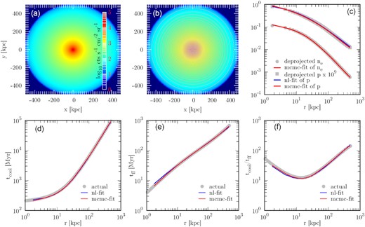
Testing the projection, deprojection, and reconstruction method for a 1D (spherically symmetric) model without any cavity as described in Section 2.1.1. Panel (a): projected surface brightness map in 2.0−14.0 keV using pass. Although the brightness is given in actual units, remember that this cluster is placed at a redshift of 10−3 and, therefore, appears to have an unrealistically high surface brightness. If put at higher redshifts, this cluster would have a much more realistic absolute surface brightness. Panel (b): annuli considered for deprojecting the spectra. We only plot every third annulus considered originally to increase visibility. Panel (c): deprojected electron density (ne) and pressure (p) profiles, along with the fits obtained for them in the two fitting methods considered. The bottom panels show the inferred properties viz., tcool (panel d), tff (panel e), and tcool/tff (panel f), and their theoretical values (grey points).
3 RESULTS
3.1 The fits
We present results of the fits in Fig. 3 for all the cases mentioned in table 1. Note that the pressure is not directly fit in mcmc-fit; it only fits the density and the pressure is obtained by multiplying the temperature and density profiles. We notice that the fits are good in both the methods in most of the cases except for tiny differences at very small radii. This difference is due to the presence of cavities in the core that cause the pressure there to become non-smooth and even hard to fit in some cases. The difference, however, is prominent in bh2a, simt1000, simt1000th0, and simt1910 cases (marked by orange background in the figure). In the case of bh2a (with a 1012-M⊙ point mass at the centre), the nl-fit works better as it does not assume a parametric form for the fitted potential and can easily fit an unknown potential. This would also be true for a BCG in case its mass is known inaccurately. In simt1000, although the fits are not very good, they roughly recover the trend. The one case, where mcmc-fit fails completely is simt1000th0 (viewing angle along the jet axis) where the deprojected density and hence the pressure goes to zero for r ≲ 20 kpc. This is because, for such a projection, the bubble appears to be a hole at the centre that, therefore, causes the deprojection method (equation 2, which assumes spherical symmetry) to fail as the surface brightness decreases towards the centre instead of increasing. Since the inner slope in mcmc-fit is fixed to a known BCG potential, i.e. a known vc (equation 10), it does not follow the negative slope of the obtained pressure. On the other hand, the nl-fit method being independent of the form of the potential recovers the pressure trend. As we will see later, this badly affects the ability for mcmc-fit to estimate tcool. A similar reasoning can also be attributed to the bad fitting of mcmc-fit method in bh2a case. However, the value of the black hole mass considered in this case is very large compared to realistic SMBHs that usually have masses |$\lesssim 10^{10} \rm M_\odot$|. This example illustrates the fallibility of the mcmc-fit methods when the actual potential differs qualitatively from the assumed form.
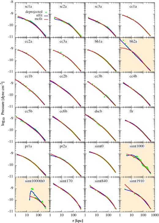
Best fit to the deprojected pressure data points (green points). The solid blue and red lines represent nl-fit and mcmc-fit, respectively. Cases that are not fitted well are shown with an orange background. We keep the same orange background in the next few figures for the results obtained from these cases. Note that the effect of cavities in the deprojected ‘sc’ models appears at r < 2r0 because the cavities are placed at z = ±r0.
3.2 Recovering tff
We also are able to recover the free-fall time, tff, for most of the cases (see Fig. 4) quite well. As mentioned earlier, the mcmc-fit method retrieves the tff better since we use the correct potential for the BCG in this method. The nl-fit method is also able to recover the free-fall time to a good accuracy except in the cases where the deprojected pressure does not follow the assumed pressure profile very well, i.e. when the pressure distribution is disturbed by turbulence or when there is a big cavity in the central region. This is because a central cavity makes the deprojected pressure profile flatter than the correct profile. This leads to an underestimation of gravitational acceleration (g) and, therefore, an overestimation of tff since tff|$= \left(-{2\:\rho \: r}/{{\rm d}P/{\rm d}r}\right)^{1/2}$|, for example, in sc2a and sim1910. Although sc3a has a cavity size (40 kpc) bigger than sc2a (20 kpc), it recovers tff better. This is mainly due to a poor pressure fit in sc2a that shows a more prominent kink in the deprojected pressure, leading to a shallower pressure fit.
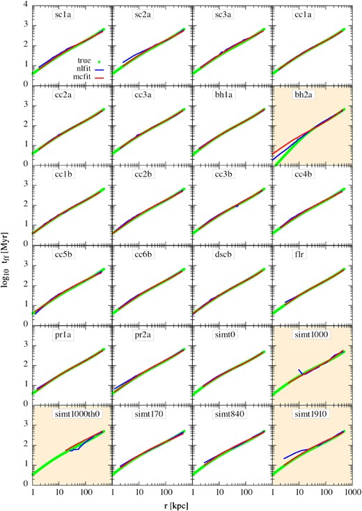
Reconstruction of tff (equation 5) using the best-fitting parameters from both the fits. The red and blue lines show the reconstructions for mlfit and nlfit, respectively. The green circles represent the true free-fall time estimated from the known mass of the toy models/simulations. The panels with orange background represent slightly poor fits as shown in Fig. 3.
The figure also shows that, in case of an unexpected gravitational potential at the centre, such as bh2a, profiles are better fitted by the nl-fit method. The mcmc-fit method fails to account for the extra potential in such cases. A way to get around this issue in this method could be to allow fitting for vc. The nl-fit, however, proves to be a less effective method at recovering the tff in the simulated cavity situations (sim1000, simt1000th0, sim1910) than the mcmc-fit method. We conclude that while estimating tff, we can use mcmc-fit in cases where the central potential is known but should switch to nl-fit in the cases where we have limited information on the central potential.
3.3 Recovering tcool
We use the definition of the cooling time as given in equation (4). Note that, while nl-fit considers the deprojected ne and T for calculating the tcool, mcmc-fit considers the best-fitting ne and the deprojected temperature for this purpose. As we will see later, this is the reason that nl-fit can provide a better estimate of tcool than mcmc-fit.
The ‘actual’ tcool and the retrieved profiles are shown in Fig. 5. The green points represent the actual tcool, whereas, the solid blue (red) line represents the profiles obtained using the nl-fit (mcmc-fit) method. Clearly, both methods reproduce the actual tcool profiles quite well in most cases. However, nl-fit retrieves tcool better than mcmc-fit in general, specifically in the cases where the fit to the deprojected pressure is not good for mcmc-fit viz. bh2a, sim1000th0, and simt1910. The nl-fit, however, shows small bumps in tcool due to the direct use of deprojected density instead of a fitted density. In the presence of a spherical cavity, tcool is overestimated by both methods – the bigger the cavity, the larger is the discrepancy. This is because in observations the density is obtained from the total surface brightness of an annulus and assuming that the emissivity throughout the spherical shell is constant (see 2). This leads to an overall lower density of the shell to match the lower surface brightness. On the other hand, the ‘actual’ tcool obtained from the models/data using equation (12) excludes any cell that has very low emissivity. Therefore, while the information of a cavity is imprinted in the density estimation of nl-fit or mcmc-fit, the ‘actual’ tcool is not much affected by the presence of cavities. This is the reason that the nl-fit or mcmc-fit overestimates tcool.
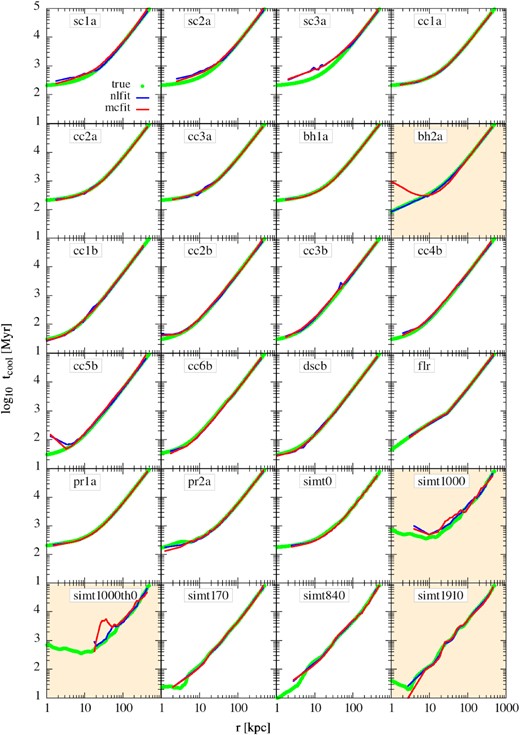
Reconstruction of tcool (equation 4) using the deprojected density and temperatures (in case of nl-fit) or using the best-fitting parameters (in case of mcmc-fit). The blue and red lines represent results from nlfit and mcfit methods, respectively. The green circles are the estimated cooling time from the toy models/simulations as described in Section 3.3. The panels with orange background represent cases that have poor fits as shown in Fig. 3.
Surprisingly, conical cavity models and the displaced spherical cavity model do not show such an overestimation of the tcool. This is perhaps due to a small solid angle subtended by these cavities leading to a much lower volume occupied by them at any radius compared to the spherical cavities. Since the spherical cavities are connected at the centre of the cluster, they can take up almost all the volume at small radii and hence produce relatively low surface brightness. It is, therefore, interesting to also note that for any cluster where the AGN is switched off for a considerable time so that the cavities have risen to a significant distance, the cavities do not much affect the measurement of the tcool. Now, since tcool ∝ 1/n and that the average value of the density due to the cavity is given as navg/n = cos θcav (in an approximate volume-averaged sense), one can roughly estimate the effect of such cavities in real observations as tcool, obs/tcool = n/navg = 1/cos θcav at any given radius. For example, in the case of sc3a at r = 10 kpc, we estimate that θcav ≈ 70° and, therefore, tcool, obs/tcool ≈ 3, roughly consistent with the recovered tcool (see Fig. 5). On the other hand, the same argument leads to tcool, obs/tcool ≈ 1.3 in the case of cc3b where hcav = 50 kpc and θcav = 45°.
3.4 Recovering tcool/tff
In Fig. 6, we plot the recovered tcool/tff from both the methods and compare them with the ‘actual’ tcool/tff profiles obtained from the toy models/simulations. We discuss the results for each subcategory in the following subsections.
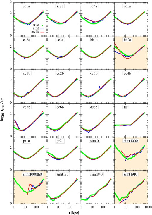
Reconstruction of tcool/tff using the best-fitting parameters from nlfit (blue line) and mcfit (red line). The green points are the true tcool/tff ratio of the toy models/simulations.
3.4.1 Cavity models
As pointed out earlier that both the analysis methods (nl-fit and mcmc-fit) are able to recover the free-fall time (tff) in most cases but overestimate the cooling time (tcool) in some cases where there is a cavity subtending a large solid angle present inside the cluster. Clearly, the tcool/tff ratio is also overestimated in those cases. The most prominent example of such a case is the sc3a (spherical cavity of size 40 kpc) where min(tcool/tff) is overestimated almost by a factor of 2−3. In another example, the methods also overestimate the tcool/tff values within ≲ 5 kpc in cc5b (conical cavity of size 50 kpc and viewed down the barrel, i.e. θview = 0°) due to the projection effects that create a hole in the surface brightness profile. This causes the deprojection method to perform poorly in recovering the density and temperature profiles towards the centre. Fortunately, the effect is only noticeable in the very first bin, and therefore, does not affect the minimum value of the tcool/tff that occurs at r ∼ 10 kpc. Based on the discussion in Sections 3.3 and 3.2, we conclude that, in the presence of cavities, the error in tcool/tff ratio is mostly driven by the error in tcool. The recovered tcool/tff ratio differs from the actual tcool/tff if the solid angle subtended by the cavity at the centre is large.
3.4.2 Extra potential
As noted in the previous paragraph that the obtained tcool/tff profiles are mostly affected by the estimates of tcool than tff, since tff is well estimated in most of the cases. One particular toy model, where the estimation of both the tcool and tff fails in mcmc-fit method is bh2a. Therefore, the tcool/tff profile also deviates from the true one in this case. On the other hand, nl-fit performs much better for this case and recovers the min(tcool/tff) value but deviates from the actual profile within ≲ 10 kpc mostly due to the pressure profile not being a simple double power-law. We should, however, keep in mind that such a massive black hole is not realistic. Any extra potential, if it exists inside the BCG, will either be small (like bh1a) where the tcool/tff profiles are recovered very accurately, or will manifest its presence in the observed vc of the BCG (a parameter in the BCG potential). However, in case the extra potential has a separate profile than the assumed profile of the BCG (either in addition to or instead of), nl-fit provides a better way to estimate tcool/tff.
3.4.3 With density perturbations
Fig. 6 shows that both the reconstruction methods are able to recover the actual tcool/tff profiles for these models to a great extent. Although nl-fit underestimates tcool/tff in pr2a (containing large fluctuations), this is entirely due to the overestimation of the tff by this method. The mcmc-fit, on the other hand, performs much better to estimate the ratio due to the known potential at the centre. We, therefore, conclude that as long as the perturbations in the system are small, both the methods work quite well. The recovered tcool/tff, however, may be affected only if the amplitude of density fluctuations is ≳ 1.
3.4.4 Recovering a floor
As mentioned in Section 2.1.5, we want to check if we could find a floor in tcool/tff (if it is present) in the core. We find that both the methods are able to recover the floor in tcool/tff (panel flr in Fig. 6). Surprisingly, H17 does not find such a floor in their data despite having clusters with entropy ∝ r2/3 (an indication of a floor in tcool/tff) in the inner region, instead, they find a slight upturn in the tcool/tff profile at smaller radii (their Fig. 7). They argued that the absence of the tcool/tff floor may be because of the increasing impact of the density inhomogeneity towards the centre. In the current analysis, we find that the both nl-fit and mcmc-fit methods are not affected much by the presence of slight density fluctuations but can be seriously affected if the density inhomogeneity is ≳ 1. However, even if they are affected, the effect has been to flatten out rather than upturn the tcool/tff profile at small radii (see panel pr2a in Fig. 6 and related discussion in Section 3.4.3). Therefore, it seems very likely that both the methods would pick up the floor if it is present. This, therefore, means that there is probably no such floor present in the H17 data and that the clusters do not necessarily have to have a floor in tcool/tff even if they have entropy ∝ r2/3.
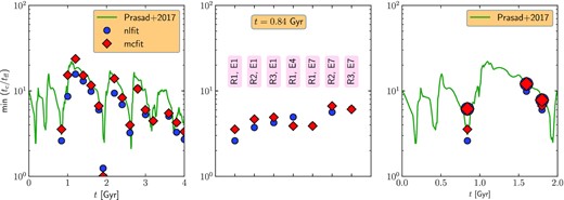
Comparing the min(tcool/tff) recovered from the nlfit and mcfit fits with the angular averaged values from the simulation. Left-hand panel: min(tcool/tff) values obtained at different snapshots of the simulation from theory (green solid line), nlfit (blue circles), and mcfit (red diamonds). Middle panel: min(tcool/tff) values at t = 0.84 Gyr for different cases with changing the observed bin-size or the observational spectral energy band. The labels R1 (default resolution), R2, and R3 represent the central bin sizes of 2.5, 5.5, and 10 kpc, respectively, and the energy bands E1, E4, and E7 represent 0.1−15, 0.4−10, and 0.7−12 keV, respectively. Right-hand panel: the effect of raising the lower energy bound of the observed spectra (shown by larger points). The very low min(tcool/tff) values seem to rise by a factor of 2−3, whereas higher min(tcool/tff) values do not increase significantly.
Although the above conclusion seems puzzling, the discrepancy can be understood in the following manner. As described by H17 (their section 7), tcool/tff ∝ 1/(T1/2 × Λ) for an entropy profile, K ∝ r2/3 (both tcool and tff are proportional to radius, latter because the potential is close to an isothermal sphere). Here, Λ is the cooling efficiency in units of erg s−1 cm3. We see that in this case tcool/tff does not directly depend on the radius. However, if the temperature has a radial dependence, it also gets imprinted on the tcool/tff profile. Therefore, we speculate that the absence of a floor in the observed tcool/tff ratio despite the presence of K ∝ r2/3 entropy profile indicates a temperature variation in that region. It is well known that the temperature decreases towards the centre in cool cores. So if the cooling function is flat or has a positive slope (as expected for free–free emission), the tcool/tff ratio is expected to increase inwards in the very centre of cool cores.
3.4.5 Simulated cases
In the simulated cases, as already mentioned, although the mcmc-fit recovers the tff better than nl-fit, it suffers from poor performance in recovering the cooling time-scale. The overall tcool/tff is still overestimated for some cases in both the methods. As shown in case of sc3a, we also find a similar effect of cavity in sim1000 and even more in simt1000th0. Surprisingly, in the cases where the ‘actual’ tcool/tff profile is expected to fall below 5 (cases simt170, simt840, and simt1910), both the methods are able to recover the profile, although not all the way till the centre (due to the resolution limit). This may be due to the absence of large cavities since the AGN has not started yet and the cluster is still cooling. We speculate that the effect of cooling phase at the centre would be to increase the density and temperature fluctuations, similar to case pr2a and, therefore, to affect tcool/tff in a similar way.
A better comparison of both the methods (nl-fit and mcmc-fit) can be seen in the left-hand panel of Fig. 7 that compiles the min(tcool/tff) obtained from both these methods and the actual values from simulations. The figure re-iterates the earlier point that both the methods do recover the min(tcool/tff) quite well throughout the duty cycle of an AGN. This means that the discrepancy between the observed and simulated clusters, namely that the simulations show more instances of tcool/tff ≲ 10, may not be due to any bias present in the analysis techniques. However, there may be several other effects, such as the resolution of the central bins and the inability to observe cooler gas, that can affect the estimation of the min(tcool/tff). We address these issues in Section 4.
3.5 Recovering the mass profile
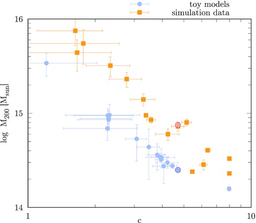
Retrieved virial mass M200 and concentration parameter (c) from mcmc-fit. The blue hashed circle shows the original value used for these toy models and the red circle represents the value used in the simulation setup. A degeneracy in M200−c is clearly visible in both toy models and the simulation. This is discussed more in Section 3.5.
Although, the above estimate is for x ≪ 1, the clusters considered here have virial radii of ≈1300 and ≈1900 kpc for the toy models and the simulations, respectively. This means that for toy models, x < 0.4 and for the simulated cluster, x < 0.25 since we use a box size of 500 kpc. In any case, we find that the above-mentioned degeneracy remains for x ≲ 0.2 but becomes increasingly flatter for higher x. Fig. 9 shows the M200−c degeneracy in the NFW potential for different values of the extent of the X-ray data (x; corresponding to different line-styles) and acceleration (indicated by the colour of the lines). We see that the degeneracy changes from M200 c2.2 ∼ const at x = 0.1 to M200 c1.7 ∼ const at x = 0.2 (comparable with Fig. 8), and finally vanishes at x ∼ 0.8. We, therefore, suggest caution while interpreting the total mass obtained from the X-ray spectral fitting methods presented in this paper, if there are not sufficient photons received from close to the virial radius.
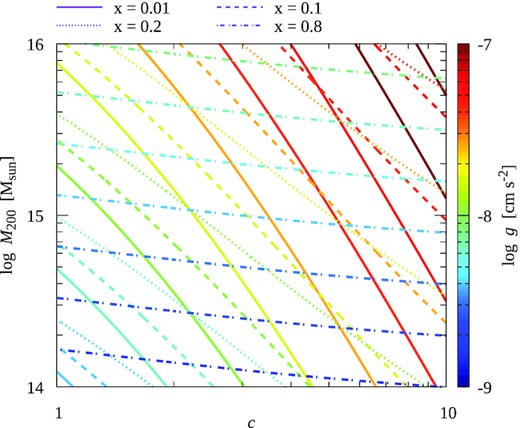
M200−c degeneracy in the NFW profile (9). Different line styles represent different values of x = r/r200 and the colour of the lines represent the gravitational acceleration, g. Although the degeneracy follows equation (14) for x ≪ 1, it remains a concern even for slightly higher x. The mass uncertainty becomes negligible at x ∼ 1.
4 DISCUSSION
4.1 Effect of central resolution
One of the limitations of the observations is the radial bin size over which the spectra are measured. The sizes of the bins are often determined by considering a minimum X-ray count in a bin so that there are sufficient photon statistics for estimating the density and temperature. Given that the min(tcool/tff) often arises within the central ∼20 kpc, not resolving this region creates a problem specifically for distant clusters. It limits our ability to look into the very central region where tcool may be significantly different from the value at larger radii. To investigate this possibility, we re-do our fits for the simt840 case but with a larger central bin-size. We increase the central bin size from 2.5 (default; case R1 in Fig. 7) to 5.5 (case R2) and 10 kpc (case R3). We find that the tcool/tff increases only by a factor of 2 at most (see the right-hand panel of Fig. 7). Given that case R1 is able to recover a min(tcool/tff) value of close to 2–3, we conclude that coarsening the radial bins would not immediately move the cluster above the tcool/tff =10 line. We also notice in the right-hand panel of Fig. 7 that coarsening the radial resolution has little effect in a state with 5 ≲ tcool/tff ≲ 10. In other words, a tcool/tff ≲ 10 cluster should always be detected as a tcool/tff ≲ 10 cluster.
4.2 Observational energy band
Throughout our paper, we have used spectra with a bandwidth of 0.1−15 keV, whereas, most of the analysis of the Chandra spectra is done for the energy range of 0.7−12 keV. Ideally, such observational bias can neglect the contribution of the T ≲ 5 × 10⁶ K gas towards overall cooling in that region. Since cooling increases with decreasing temperature in ∼105−(5 × 10⁶) K range (especially in isobaric conditions), missing soft-X-ray photons can underestimate cooling by the lower temperature gas and thus overestimate the tcool/tff ratio.
We perform a few experiments on the simulation data to understand the effect of the observational energy band. We trim the spectra for t = 0.84, 1.6, and 1.8 Gyr (corresponding min(tcool/tff) values are ≈3, 12, and 6) to 0.7−12.0 keV range5 and then perform the spectral fitting procedures as described in Section 2. We also use a coarse spatial binning to see the combined effect on the tcool/tff values. The result is shown in the right-hand panel of Fig. 7. It shows that while higher min(tcool/tff) values do not change much due to a coarser spatial binning or a harder spectral energy band, the lower min(tcool/tff) values can be overestimated at most by a factor of 2−3. Our experiments, therefore, suggest that observations in softer X-ray emission (≲ 1 keV) are required to recover the min(tcool/tff)≲ 5 clusters. However, Chandra observations at such low energies are difficult due to (a) the contamination that has built on the Chandra optical blocking filters, reducing the effective area for energies less than 1 keV, and (b) additional absorption by the foreground.
4.3 Photon statistics and error in real observations
So far, we have not considered realistic photon statistics while fitting the spectra in xspec, a problem often faced in real observations due to the low number of X-ray photons. To understand what the photon statistics may look like, we perform some tests on our fiducial toy model (as presented in Section 2.5) by assuming that the photons are detected through an instrument with an effective area, Aeff = 100 cm2, exposure time texp = 300 ks, and that the photons suffer through Poisson statistics. The statistics is included by switching on cstat while fitting in xspec. The analysis is repeated by assuming a higher metallicity (Z = 0.6 Z⊙) as well as a realistic redshift (z = 0.2) for the cluster. In the high-redshift case, we binned the photons in coarser spatial and energy bins due to the low photon count. The results of this experiment are shown in Fig. 10. In the nl-fit method (upper panel), the introduction of cstat does not alter the results for the low-redshift cases. Additionally, the error bars are also negligible (owing to a large photon count), except at the innermost radius where the error in tff is slightly higher due to a large cell width to radius ratio. For the high-redshift cases, the photon statistics become important even after we bin the data in coarser spatial and energy bins. Fitting the spectra with a low photon number thus introduces a non-negligible error in both tcool and tff, which is then propagated to tcool/tff (see Appendix A for details of the error calculation). The error bars, however, are mostly negligible in tcool and tff, except at the radius where tcool/tff error can be close to 30 per cent. Overall, The recovered values also follow the actual values quite well.
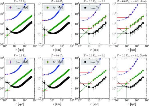
Effects of including realistic photon statistics and redshift in recovering tcool, tff, and tcool/tff. The right-hand column also shows the results if we consider the cloudy-17 cooling rates. Top panels show the results for the nl-fit method and the bottom panels show the results for the mcmc-fit method. The dashed lines show the actual profiles for the fiducial toy model.
The uncertainties obtained from xspec towards the density and temperature are also used in the mcmc-fit method to obtain fits for ρ0, M200, and c. The introduction of the photon statistics does not significantly improve/worsen the fit for the above quantities, as can be seen from the mean values recovered for tcool, tff, and tcool/tff (bottom panel of Fig. 10). The error in ρa, M200, and c are also comparable to the fits without the photon statistics (|$\sim 10\!-\!20{{\ \rm per\ cent}}$|). The recovered profiles overall track the actual profiles in the toy model. The error bars in the recovered quantities are also |$\lesssim 30{{\ \rm per\ cent}}$| except for the innermost radius where the spatial resolution is the main source of error in estimating tff and tcool/tff.
4.4 Discrepancy between observations and simulations
The biases introduced by observational/modelling limitations (limited angular/spatial resolution, lack of soft X-ray spectra, assumed the functional form of the potential, etc.) tend to overestimate tcool/tff by a factor of ≲ 3 in the worst-case scenario that we explore, especially for the smallest tcool/tff.
Fig. 11 in Prasad et al. (2018) shows a comparison of the distribution of simulated (with and without BCG potential and star formation rate ∼5M⊙ yr−1) and observed (reported in Pulido et al. 2018) cool-core clusters. The observational sample from Pulido et al. (2018) shows 55 clusters and groups with molecular mass between 108 and 1011M⊙, and star formation rate between 0.5 and 270 M⊙ yr−1. In contrast to simulations, the observed histogram shows a clear lack of systems with min(tcool/tff) ≲ 5. This may be largely due to the overestimation of tcool/tff in the core because of insufficient spatial resolution (Section 4.1) and the lack of soft X-ray spectrum (Section 4.2) that mostly affect the coolest cores. The same figure in Prasad et al. (2018) shows that the peaks of the observed and simulated min(tcool/tff) histograms also do not match. The observational peak is narrower and occurs at a slightly higher value (min(tcool/tff) ≈11) compared to the simulations (NFW potential run peaks at min(tcool/tff) ≈ 9 and the NFW+BCG run has a broad peak between 7 and 11). Thus the observed and simulated X-ray properties of cool cores can be reconciled.
The observational samples of cool-core clusters and groups have different selection criteria (e.g. Voit & Donahue 2015; Lakhchaura et al. 2016; Pulido et al. 2018), and the distribution of cool-core properties may differ because of that. But the biggest discrepancy from simulations in most of them is the lack of systems with min(tcool/tff) ≲ 5, which can be reconciled as discussed in the previous paragraph.
A related recent puzzle is the discovery of a cooling flow in the core of the Phoenix cluster with min(tcool/tff) ≈1 in its very centre (McDonald et al. 2019). How can we explain such a system when observations indicate a general absence of systems having cool cores with min(tcool/tff) ≲ 5? Phoenix, despite being a high-redshift cluster (z ≈ 0.6), has been observed with an exquisite spatial resolution (it was possible to use two radial bins within 10 kpc; this allowed McDonald et al. 2019 to properly separate the AGN and cluster core emission). Moreover, it is a massive/hot cluster with a peak temperature of ≈14 keV. Being hot, the determination of density and temperature in the dense/cool core is not affected as much by the absence of soft X-ray spectra.
Last but not the least, the simulations still very crudely model (or even totally ignore) very important physical processes such as thermal conduction, magnetic fields, angular momentum transport within the central ∼ kpc (Gaspari et al. 2013; Prasad et al. 2017), which can affect the distribution of min(tcool/tff). Simulations may not only be missing important physics, but they also have not exhaustively explored various important parameters (such as feedback efficiency).
5 CONCLUSIONS
In this paper, we have studied various models of the intracluster medium using some standard techniques of X-ray spectral analysis. We have created toy models resembling different kinds of non-hydrostatic features such as cavities, inhomogeneities, unknown potential, etc., to create projected X-ray spectra. We then deproject them using often-used tools (especially, Nulsen, Powell & Vikhlinin 2010; Lakhchaura et al. 2016) to recover various physically important quantities such as tcool, tff, and tcool/tff. Comparing these recovered quantities with the values from the input models allow us to examine the bias introduced by X-ray observations and the analysis methods. We also use our projection-deprojection method on realistic simulation data to obtain min(tcool/tff) during various stages of AGN activity and compare them with the ratio obtained from observational samples (such as Hogan et al. 2017; Pulido et al. 2018). We summarize the main findings of our paper as follows:
The non-linear fitting method used by Lakhchaura et al. (2016) and the MCMC method (described by Nulsen et al. 2010) used by more recent studies (such as Hogan et al. 2017) recover the min(tcool/tff) of the non-cooling as well as the cool-core clusters fairly well. The presence of large cavities leads to overestimating the tcool (and hence tcool/tff) in both methods. The amount of overestimation depends on the solid angle subtended by the cavity at the cluster centre. The nl-fit method works better for the systems where the gravitational potential at the centre is not known accurately. It also better estimates the cooling time.
We are able to recover min(tcool/tff) as low as 2−3 by analysing the simulation data. We, however, find a factor of ≲ 3 overestimation of the min(tcool/tff) if the spatial/angular resolution is ≳ 10 kpc and if soft X-ray spectrum is not available. The observed lack of cool-core clusters below min(tcool/tff) <5 (Pulido et al. 2018) compared to the value from AGN simulations may arise due to poor spatial resolution and the lack of soft X-ray spectra. Additionally, there may be additional heating in cool-core clusters that can raise the tcool/tff value above that seen in AGN feedback simulations.
The estimated cluster mass (M200) from the mcmc-fit method suffers from a systematic degeneracy with the estimated concentration parameter, c. Such degeneracy can cause the dark matter mass estimates to be off by a factor of 5−10 from the original value and arises purely due to the form of the NFW profile at small r/r200 (≲ 0.2) values. We stress that this degeneracy goes away if one considers the X-ray data for r/r200 ∼ 1 (as used in Nagai, Vikhlinin & Kravtsov 2007). This also emphasizes the need for X-ray observations from close to the virial radius of a galaxy cluster in order for them to be used as useful cosmological probes, which requires an accurate cluster mass.
This paper, therefore, dives deep into understanding the biases of the analysis methods often used to study the intracluster medium. Although our simplistic toy models may not cover all the possible complications arising in a real ICM, it provides an overall idea of how much various complications can affect the estimated tcool/tff. We hope that this study will be a useful benchmark to characterize such biases.
ACKNOWLEDGEMENTS
We thank Nazma Islam for her help in solving technical issues in xspec. We also thank the anonymous referee for the helpful comments on this paper. KCS acknowledges support from the Israeli Science Foundation (ISF grant no. 2190/20). PS acknowledges a Swarnajayanti Fellowship (DST/SJF/PSA-03/2016-17) and a National Supercomputing Mission (NSM) grant from the Department of Science and Technology, India.
DATA AVAILABILITY
All the data/codes used in this paper can be found in this paper or under their cited references.
Footnotes
For entropy, S ∝ r2/3, the temperature, |$T\propto n_{\rm e}^{2/3} r^{2/3}$|. Now since, tcool ∝ T/(neΛ) and |$t_{\rm ff} \propto \sqrt{r/g}$|, where g ∼ P/(ner) ∝ T/r, it can be shown that tcool/tff ∝ 1/Λ, which is roughly independent of the radius.
pass is available freely from https://github.com/kcsarkar.
More recent cooling curves, such as in cloudy-17 (Ferland et al. 2017) show significantly lower cooling rates for T ≲ 106 K and for lower metallicity (see Fig. A1). This discrepancy, however, is only ≈1.5 for 106−(5 × 10⁶) K gas, above which the discrepancy is even lower. Thus, considering new cooling rates will not change our results much since the plasma in our toy models and simulations has temperature T ≳ 107 K.
While calculating the average quantities, we consider that gas with T < 0.5 keV has zero emissivity to avoid any contamination by the cold/warm gas in the estimated quantities. This is done keeping in mind that our method of analysis only uses X-ray data.
Although Chandra energy band is ≈0.7−7 keV, one usually does not have many photons past 7 keV. Therefore, we do not expect any significant change in the xspec fits even though we included slightly higher energy bins.
REFERENCES
APPENDIX: ERROR CALCULATION
Errors in tcool, tff, and in tcool/tff ratio are determined numerically from the obtained uncertainties in the fit parameters viz. P0, a, α1, α2, T, and ne (for nl-fit) and M200, c, T, and ne (for mcmc-fit). The numerical uncertainty for any quantity Q ≡ Q(r, p1, p2, ...) is given as

