


ABSTRACT
Quasi-periodic oscillations (QPOs) are often present in the X-ray flux from accreting stellar-mass black holes (BHs). If they are due to relativistic (Lense–Thirring) precession of an inner accretion flow which is misaligned with the disc, the iron emission line caused by irradiation of the disc by the inner flow will rock systematically between red and blue shifted during each QPO cycle. Here, we conduct phase-resolved spectroscopy of an ∼2.2 Hz type-C QPO from the BH X-ray binary GRS 1915+105, observed simultaneously with NICER and NuSTAR. We apply a tomographic model in order to constrain the QPO phase-dependent illumination profile of the disc. We detect the predicted QPO phase-dependent shifts of the iron line centroid energy, with our best fit featuring an asymmetric illumination profile (>2σ confidence). The observed line energy shifts can alternatively be explained by the spiral density waves of the accretion-ejection instability model. However, we additionally measure a significant (>3σ) modulation in reflection fraction, strongly favouring a geometric QPO origin. We infer that the disc is misaligned with previously observed jet ejections, which is consistent with the model of a truncated disc with an inner precessing hot flow. However, our inferred disc inner radius is small (rin ∼ 1.4 GM/c2). For this disc inner radius, Lense–Thirring precession cannot reproduce the observed QPO frequency. In fact, this disc inner radius is incompatible with the predictions of all well-studied QPO models in the literature.
1 INTRODUCTION
In a black hole (BH) X-ray binary system (XRB), the BH accretes matter from its stellar companion via a geometrically thin, optically thick accretion disc (Novikov & Thorne 1973; Shakura & Sunyaev 1973) which radiates a multitemperature blackbody spectrum. We also see a power-law component as a result of photons being Compton up-scattered by a population of hot electrons near the central BH (Thorne & Price 1975; Sunyaev & Trümper 1979), typically referred to as the corona. This power-law component has lower and upper cutoffs determined by the temperature of the seed photons and electrons, respectively. The third and final major spectral component comes from a fraction of the coronal photons irradiating the disc and being scattered into our line of sight. As a result of being reprocessed in the disc’s atmosphere, these photons have a reflection spectrum with characteristic features. The scattering produces a broad Compton hump peaking at ∼20–30 keV (e.g. Lightman & Rybicki 1980); and there are many spectral lines, the strongest being the Fe Kα line at ∼6.4 keV (George & Fabian 1991; Ross & Fabian 2005; García et al. 2013a). These reflection features are distorted and broadened from their rest-frame energies by Doppler shifting and boosting due to the relativistic orbital speed of the disc material, and general relativistic effects due to the strong field gravity around the compact object (Fabian et al. 1989). Modelling of these reflection features has been used to trace the inner disc radius, which leads to the BH spin if the disc extends down to the innermost circular stable orbit (ISCO; e.g. Plant et al. 2014; García et al. 2015).
XRBs are usually discovered as transient events, as they undergo outbursts typically lasting weeks to months. During these outbursts they increase in X-ray flux from the quiescent level by multiple orders of magnitude, but are also seen to transition between different canonical X-ray spectral-timing accretion states. After rising from quiescence, the source is initially in the hard state, where the X-ray spectrum is dominated by the power-law component. After rising to the peak of the hard state, the source transitions to the disc-dominated soft state via the intermediate state. Eventually, the source transitions back to the hard state, always at a lower flux than the hard-to-soft transition, and then finally back to quiescence. The radio properties are correlated with the X-ray state, with a steady jet observed in the hard state and a discrete ejection observed during the hard-to-soft transition (e.g. Fender, Belloni & Gallo 2004; Done, Gierliński & Kubota 2007; Belloni 2010; Fender & Belloni 2012).
While the physics of the accretion disc is relatively well understood, the structure of the corona is still debated. One popular model is the truncated disc model (Eardley, Lightman & Shapiro 1975; Ichimaru 1977; Done et al. 2007) whereby, in the hard and intermediate states, the disc is truncated at some radius greater than the ISCO of the BH; inside of this truncation radius the flow becomes geometrically thick and optically thin, which is the observed corona. In this model, the truncation radius of the thin disc decreases during the rise from quiescence until it reaches the ISCO in the soft state, before it moves out once again during the decay back to quiescence. Other models suggest that the corona sits above the disc (Galeev, Rosner & Vaiana 1979; Haardt & Maraschi 1991), or that the corona is actually outflowing in such a way that is the base of a jet (Miyamoto & Kitamoto 1991; Fender et al. 1999; Markoff, Nowak & Wilms 2005).
Quasi-periodic oscillations (QPOs) are often seen in the light curves of XRBs. These are characterized by a narrow peak with finite width in their power spectra, and are often accompanied by higher harmonics (see e.g. for a review Ingram & Motta 2019). Here we focus on a ‘type-C’ low-frequency QPO in a BH XRB. These are seen with fundamental frequency evolving from ∼0.1 to 10 Hz as the spectral state evolves through the hard and intermediate states (Wijnands & van der Klis 1999; Van der Klis 2006; Motta et al. 2011).
Models of low-frequency QPOs in the literature (see Ingram & Motta 2019 for a discussion) can generally be classified into two types: intrinsic – whereby the intrinsic luminosity of the accretion flow oscillates – or geometric – whereby the observed oscillation in flux is instead caused by a variation of the beaming pattern of the corona.
Intrinsic models include resonant oscillations in a property of the accretion flow such as accretion rate, pressure, or electron temperature (e.g. Cabanac et al. 2010; O’Neill et al. 2011; Karpouzas et al. 2021). For instance, an oscillating shock at the interface between disc and corona (the propagating oscillatory shock – POS – model: Chakrabarti & Molteni 1993), or spiral density waves in the disc set-up by instabilities in the vertical magnetic field (the accretion ejection instability – AEI – model: Tagger & Pellat 1999).
Geometric models mostly focus on relativistic (Lense–Thirring) precession (Lense & Thirring 1918), which is induced in orbits that are not aligned with the BH spin axis by the frame dragging effect. The relativistic precession model (RPM: Stella & Vietri 1998; Stella, Vietri & Morsink 1999) considers precession frequencies of a test mass in the accretion flow (representing e.g. a hotspot or overdensity. Another example is corrugation modes (c modes): transverse standing waves in the disc height with resonant angular frequency related to the Lense–Thirring precession frequency (Wagoner 1999). Schnittman, Homan & Miller (2006) instead considered a precessing ring in the disc. Ingram, Done & Fragile (2009) proposed that within the truncated disc model the entire corona precesses (as seen in simulations by Fragile et al. 2007) whereas the disc stays stationary due to viscous diffusion (Bardeen & Petterson 1975; Liska et al. 2019). The precession frequency of the corona is a weighted average over all radii in the corona of the test mass Lense–Thirring precession frequency (Motta et al. 2018). Alternatively, or additionally, the jet base could be precessing, as has recently been seen in General Relativistic Magneto-hydrodynamic (GRMHD) simulations (Liska et al. 2018). We note that some of the models classed here as intrinsic also include some geometrical aspect; e.g. an expanding and contracting corona in the POS model and the spiral arms in the AEI model.
Motta et al. (2015) and Heil, Uttley & Klein-Wolt (2015) showed that higher inclination sources appear to display stronger QPOs, providing strong evidence in favour of a geometrical effect rather than some intrinsic fluctuation in the X-ray luminosity. Further to this, van den Eijnden et al. (2017) found a possible inclination dependence of QPO phase lags, which also supports a geometrical origin for type-C QPOs. It is also known that the power law spectral component varies with much larger RMS than the disc component, indicating an origin in the corona (Sobolewska & Życki 2006; Axelsson, Hjalmarsdotter & Done 2013) as opposed to the disc. The precessing corona model naturally reproduces these observational properties, and additionally predicts that the reflection spectrum is modulated, as the precessing corona illuminates the disc asymmetrically. The observer sees light coming from different patches of the disc undergoing different boosting and shifting due to differing line-of-sight velocities of the disc material. Therefore an asymmetric illumination profile which varies with QPO phase will highlight different patches of the disc at different phases of the QPO cycle, and hence cause the broadening profile of the reflection spectrum to change. This effect would be seen as a ‘rocking’ of the Fe Kα line, where the profile and centroid energy change over the course of each QPO cycle (Ingram & Done 2012; You et al. 2020).
In this paper, we study the QPO phase dependence of the reflection spectrum by performing phase-resolved spectroscopy of an ∼2.2 Hz QPO from the BH XRB GRS 1915+105, using the technique first applied to the same source by Ingram & van der Klis (2015). Ingram et al. (2016) made further improvements to the technique in order to constrain a modulation in the Fe line centroid energy from the BH XRB H 1743-332, and Ingram et al. (2017) introduced a tomographic model. Likewise, Stevens & Uttley (2016) presented phase-resolved spectroscopy of GX 339-4, introducing the use of the cross-correlation function. Here, we present further sophistication to the Ingram & van der Klis (2015) phase-resolving technique, and to the tomographic model. In Section 2, we present details of our observations and data reduction procedure. In Section 3, we lay out the steps of our improved phase-resolving method. Section 4 contains the details of our tomographic model, and the results of fitting this model to the phase-resolved spectra are presented in Section 5. We discuss our results in Section 6.
2 OBSERVATIONS
The Neutron star Interior Composition ExploreR (NICER; Gendreau et al. 2016) and the Nuclear Spectroscopic Telescope ARray (NuSTAR; Harrison et al. 2013) observed GRS 1915+105 quasi-simultaneously on 8th–9th June 2018.1 The details of the observations are summarized in Table 1. In this section, we detail our data reduction procedure and present the basic spectral and timing properties of the data. When analysing the data we make use of HEASARC (2014), and custom code written in python3 (Van Rossum & Drake 2009).
Details of the simultaneous observations from NICER and NuSTAR on the 8th–9th June 2018 (MJD 58277-58278). The NICER observation was split into two, however, these are merged for our analysis. The net count-rate is reported for the background-subtracted spectra used for the flux-energy fits: 3.5–75, 3–75 keV for NuSTAR; 2.7–10 keV for NICER.
| Mission | NuSTAR | NICER | ||
|---|---|---|---|---|
| FPM A | FPM B | |||
| ObsID | 80401312002 | 1103010157 | 1103010158 | |
| Start time | 12:01:09 | 11:42:40 | 23:49:26 | |
| End time | 05:31:09 | 22:55:20 | 05:05:40 | |
| Net count rate/s−1 | 60.2 | 59.6 | 196.8 | |
| Exposure time/s | 261 66 | 265 12 | 15386 | 5033 |
2.1 NuSTAR data reduction
We used the NuSTAR analysis software, NuSTARdas v1.8.0 with heasoft v6.22. We generated a cleaned event list with associated list of good time intervals (GTIs) for both focal plane modules (FPMs) – FPMA and FPMB – using nupipeline. From this we used nuproducts to extract source and background spectra from 49.2 arcsec circular regions and generate spectral response files. We find that the source contributes >99.9 per cent of the total counts measured by NuSTAR. We did not perform a background subtraction when extracting light curves we use for the timing analysis, as the background is not expected to be variable on the QPO period. We use our own custom code to extract FPMA and FPMB source region light curves from the cleaned event list in 11 broad energy channels in the energy range 3–78 keV. We used the ftoolrbnrmf to re-bin the spectral response files into these 11 energy bands.
2.2 NICER data reduction
We used the NICER analysis software, NICERdas v2018-04-13_V004 with heasoft v6.24. We extracted the MPU-merged, uncleaned event lists with the ftoolNICERl2 for each of the two NICER observations, which we then merged together using nimpumerge and cleaned with NICERclean. We used filter and GTI files which were combined from those of the separate obs IDS using ftools ftmerge and nimaketime. This results in a single cleaned event list for the two obs IDs combined.
We extracted a flux-energy spectrum from the resulting merged event list using xselect, and estimated the instrumental background with the NICERgof.bkg version 0.5 python script (Remillard et al. 2021). We find that the source contributes 98.6 per cent of the total counts measured by NICER. Again, we did not perform a background subtraction when extracting light curves we use for the timing analysis, as the background is not expected to be variable on the QPO period. We used the spectral response files ‘nixtiref20170601v002.rmf’ and ‘nixtiaveonaxis20170601v004.arf’ from caldb. We extracted light curves from the merged event list in 40 broad energy channels in the energy range 0.3–10 keV using our own custom code. We used the ftoolrbnrmf to re-bin the spectral response files into these 40 energy bands.
2.3 Energy spectrum
Fig. 1 shows the NICER (black) and NuSTAR (red: FPMA; blue: FPMB) background subtracted flux-energy spectrum plotted as a ratio to a folded absorbed power-law model. We set the hydrogen column density to NH = 6.2 × 1022 cm−2 (the absorption model is tbabs with the abundances of Wilms, Allen & McCray 2000) and the power-law index to Γ = 2.01 for all three spectra, but allow the three spectra to each have their own normalization. We see strong reflection features including an iron line at ∼6.4 keV and a broad Compton hump peaking at ∼30 keV. We also see that the cross-calibration between NICER and NuSTAR is excellent in the ∼3–10 keV energy range in which their band passes overlap. At energies below ∼2.7 keV, the NICER spectrum includes features that are likely due to calibration uncertainties, and the ‘shelf’ of the response from higher energy photons (NASA 2021) which is dominant below ∼1 keV due to the astrophysical absorption leaving very few source photons at low energies. We therefore only consider energy channels >2.7 keV in our spectral analysis. We note there is a cross-calibration discrepancy between NuSTAR FMPA and FMPB in the energy range ∼3–3.5 keV due to a tear in the Multi Layer Insulation around NuSTAR’s FMPA (Madsen et al. 2020), so we also ignore the FMA energy channels <3.48 keV.
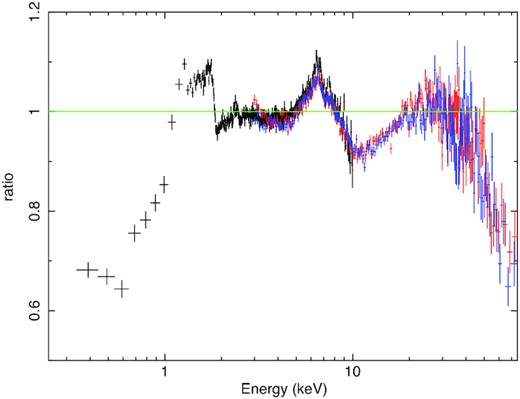
Ratio of the NICER 0.24–10 keV, and the NuSTAR FPMA and FMPB 3–75 keV spectra in black, red, and blue, respectively, to an absorbed power-law model with photon index 2.01, and absorption with hydrogen column density 6.2 × 1022 cm−2.
2.4 Power spectrum
Fig. 2 shows the 3–10 keV power spectrum calculated for the merged NICER observation (blue) and the NuSTAR observation (orange). For both observatories, we extract light curves with time-step δt from the cleaned event list. For the purposes of ensemble averaging (e.g. van der Klis 1989), we split the light curves into M segments labelled 1 ≤ m ≤ M, each having N time bins and therefore a length T = Nδt. Except for when otherwise stated we use N = 8192 and δt = 1/128 s throughout this paper, so our segments are T = 64 s long. The NICER power spectrum is calculated in the standard way [the magnitude-squared of the fast Fourier transform (FFT) of the light curve], with a constant Poisson noise level subtracted (van der Klis 1989; Uttley et al. 2014). For NuSTAR, we instead calculate the co-spectrum between the FPMA and FPMB (Bachetti et al. 2015) in order to avoid instrumental features caused by the fairly large NuSTAR deadtime of tD ≈ 2.5 ms. We also correct for the suppression of variability caused by the NuSTAR dead time using the simple formula (RMSdet/RMSintr) ≈ 1/(1 + tDrintr) = (rdet/rintr), where RMSdet and RMSintr are, respectively, the detected and intrinsic RMS variability amplitudes and rdet and rintr are the detected and intrinsic count rates (Bachetti et al. 2015). For this observation, the ratio of detected to intrinsic variability is RMSdet/RMSintr = 0.754 (recorded in the NuSTAR spectral files as the keyword ‘DEADC’). We see that the NuSTAR co-spectrum is very similar to the NICER power spectrum. In both, we see a strong low-frequency QPO with a fundamental frequency of ∼2.2 Hz and a 2nd harmonic at twice that frequency. We can classify this low-frequency QPO as ‘type-C’ based upon its frequency, RMS |$\gtrsim 15{{\ \rm per\ cent}}$|, and the presence of the ‘flat-top’ broad-band noise (see e.g. Ingram & Motta 2019 for a summary of the characteristic features of type-A, B, and C low-frequency QPOS).
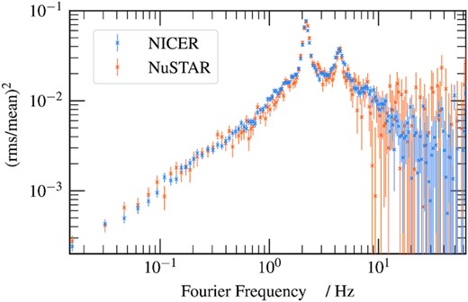
The 3–10 keV power spectra of the NICER (blue) and NuSTAR (orange) observations. The NICER spectrum is Poisson-noise subtracted, while the NuSTAR spectrum is estimated from the co-spectrum between FPMA and FMPB. The power spectra have been ensemble-averaged and geometrically re-binned to reduce the number of bins by a factor of 25.
2.5 Spectral timing state
Belloni et al. (2000) identified 15 different states from spectral and variability patterns that GRS 1915+105 transitions between (also see Huppenkothen et al. 2017), most of which have only to date been observed in one other XRB (Altamirano et al. 2011). From the flux-energy spectrum and power spectrum, it is clear that GRS 1915+105 was in the designated χ-state during this observation. The χ-state is one of the few that behaves similarly to one of the canonical states, and corresponds to the hard state. The χ-state can either be radio loud or quiet; during our X-ray observations the source was radio quiet (Motta et al. 2021). This happens to be the dimmest χ-state ever observed, preceding the transition of the source into its current heavily obscured state (Motta et al. 2021). The QPO frequency of ∼2.2 Hz is also somewhat special, since it is at around this QPO frequency when the QPO phase lags transition from positive (hard photons lag soft photons) to negative (soft photons lag hard photons): the phase lag reduces approximately linearly with the log of QPO frequency, passing through zero at νqpo ∼ 2 Hz (Reig et al. 2000; Qu et al. 2010; van den Eijnden et al. 2017; Zhang et al. 2020).
3 PHASE RESOLVED SPECTROSCOPY
The aim of phase resolved spectroscopy is to investigate how the energy spectrum of the source varies with QPO phase, a task complicated by the ‘quasi-’ nature of the oscillation which prevents more direct approaches such as phase-folding. We therefore employ the techniques pioneered by Ingram & van der Klis (2015) to consider the QPO waveform in different energy bands, considering its phase-average and first two harmonics. To do this, we extract three key pieces of information:
The amplitude (RMS) of each harmonic in each energy band σj(E). We find this by fitting an estimate of the power spectrum with a multi-Lorentzian model, as described in Section 3.3.
The phase lag of each harmonic in each energy band Δj(E), relative to the phase of the corresponding harmonic in a reference band. This comes from using the cross spectrum between the light curve of the subject energy band, and the reference band, as described in Section 3.2.
The phase difference ψ between the first two harmonics measured within the reference band. Using the FFT of the reference light curve, this is the difference between the phases in frequency bins containing the two harmonics. We use the bi-spectrum to calculate this, which is described in Section 3.4.
The following subsections which describe these parts of the analysis are each further split into two sub-subsections, with the first describing the method used, and the second presenting the results obtained from the observations analysed in this paper.
3.1 QPO frequency tracking
During the observations, the frequency of the QPO drifts over time by |$\sim \pm 5{{\ \rm per\ cent}}$|. To account for this, we identify the frequency of the QPO during each of the M segments so that we can later average Fourier products over the frequency range containing the instantaneous QPO frequency.
3.1.1 Method
As each frequency bin of a single power spectrum (without any ensemble or frequency averaging) follows a χ2 probability distribution with two degrees of freedom3 (van der Klis 1989), we are unable to use χ2 minimization for the model fit as this depends on each frequency bin following a Gaussian distribution. We therefore use the maximum likelihood estimation method described in Barret & Vaughan (2012). This method does not require the probability distribution to be Gaussian, it only requires it to be known analytically. We find best-fitting model parameters, including the frequency of the QPO fundamental, by maximizing the likelihood function calculated assuming a χ2 probability distribution with two degrees of freedom.
It is important to note that the probability distribution underlying each frequency bin of a un-averaged co-spectrum is not known analytically (Huppenkothen & Bachetti 2018). We are therefore unable to use the maximum likelihood method on the co-spectrum between FPMA and FPMB, which is why we resort to modelling the Poisson noise of the power spectrum, which does have well-understood statistics.
3.1.2 Results
Fig. 3 shows the resulting measurements of QPO frequency (black crosses) as a function of time for NuSTAR (top) and NICER (bottom). Rather than uncertainties, the error bars shown are the measured full width at half maximum (FWHM) of the Lorentzian function representing the QPO fundamental. In our fits, we restricted the QPO frequency to a range given by the running average of the QPO frequencies of the previous 5 segments ±3/2 times the running average FWHM of the previous 5 segments, starting with the QPO frequency and FWHM from the average power spectrum. This range is represented by the grey=dashed lines. To smooth out the results of our tracking algorithm4 we use a degree-15 polynomial to model QPO frequency with time, that we fit simultaneously to the NICER and NuSTAR data (the solid red line in Fig. 3). It is encouraging that the instantaneous QPO frequencies we measure here are very similar to those inferred by Huppenkothen & Bachetti (2022) using a more sophisticated method (see their fig. 23)
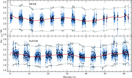
The estimated value of the QPO frequency νmax measured in each 64 s long segment of the two light curves, with the error bars denoting the estimated FWHM. The grey-dashed line show the dynamic bounds for the QPO tracking algorithm. The red line is a |$15\deg$| polynomial simultaneously fit to the estimated QPO frequencies, which we then use to get the QPO frequency at arbitrary time.
3.2 Phase lag spectrum
3.2.1 Method
For NuSTAR, we instead extract the subject band light curves from the FPMB and the reference band light curve from the FPMA to ensure that the subject and reference band signals are statistically independent of one another, and therefore the cross-spectrum contains no contribution from deadtime affected Poisson noise.
We consider the ‘shifted-and-added’ cross-spectrum of the jth QPO harmonic by first averaging over the QPO harmonic in each time segment based upon the tracked QPO frequency. For the mth segment we average over the frequency range ν = jνqpo(m)[1 ± 1/(2Q)], where we assume Q = 8 for the quality factor (a typical value for a type-C QPO; Ingram & Motta 2019), using the smoothed estimate from our QPO tracking algorithm for νqpo(m). We then average over the time segments to find the overall average value for cross-spectrum for each of the QPO harmonics.
The phase lag for the jth harmonic, Δj(E), is the argument of the averaged cross-spectrum of the corresponding harmonic, of which we estimate the uncertainties using the formula from Ingram (2019, equation 19).
3.2.2 Results
We display the measured phase lag spectrum in Fig. 4 (bottom) for NICER (blue) and NuSTAR (orange). We see that the phase lag of the QPO fundamental is almost constant with energy, which is consistent with previous RXTE observations showing that the phase lag monotonically reduces from hard lags (a positive lag versus energy gradient) to soft lags (a negative lag versus energy gradient) as the QPO frequency increases, with the cross over occurring for νqpo ∼ 2 Hz (e.g. van den Eijnden et al. 2017). Note that a slight offset between NICER and NuSTAR lags results from a phase lag between the NICER and NuSTAR reference bands. Although the offset is very small for this observation because the energy dependence of the lag is subtle, we account for it in our modelling with a floating phase offset.
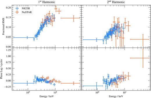
Top: The fractional RMS of the first and second harmonics of the QPO in both the NICER and NuSTAR observations in different energy bands, found by fitting lorenztian functions to the power spectrum of each energy band, which was estimated from a cross-spectrum between a broad reference energy band and a specific energy band, as described in the text. As the fractional RMS must be positive points that have Δχ2 < 1 at zero are shown without an errorbar cap. The fractional RMS is slightly diluted by background photons in the very highest NICER energy bands. Bottom: The phase lag of the first and second harmonics of the QPO, measured against a reference band. For NICER this reference band is the full energy light curve, while for NuSTAR it is the full energy light curve of FMPB.
3.3 Fractional RMS spectrum
3.3.1 Method
To calculate the fractional RMS of the QPO harmonics in each energy band, instead of the power spectrum in that energy band, we boost signal to noise by using the shift-and-added cross-spectrum |$G(\nu , E)=\frac{1}{M}\sum _m^M{G_m(\nu +\delta \nu _m,E)}$|, where δνm is the difference between the QPO frequency in that segment (from our smoothed tracking) and the average QPO frequency.
We fit a multi-Lorentzian model to the resulting power spectral estimate for each energy band. We use three Lorentzian functions: one with Q = 0 to represent the broad-band noise; and the other two with centroid frequencies and Q tied (such that the centroid frequencies are harmonically related) in order to represent the two QPO harmonics. We normalize our power spectral estimate (Belloni & Hasinger 1990) and Lorentzian functions (van Straaten et al. 2002) such that the best-fitting normalization of the two Lorentzian components representing the QPO harmonics gives their fractional RMS. We calculate 1σ uncertainties on the RMS by searching parameter space for a marginalized Δχ2 = 1.
3.3.2 Results
We display the measured RMS spectrum in Fig. 4 (top). Error bars without a lower cap correspond to points consistent with zero within 1σ. We see that, as is typically the case for type-C QPOs, the fractional RMS increases with energy for E ≲ 10 keV before levelling off. We note good agreement between NICER and NuSTAR.
3.4 Phase difference between harmonics
3.4.1 Method
In order to calculate B(νqpo), we adopt the same shift-and-add technique for the auto-bispectrum as described in the previous section for the cross-spectrum, again employing our smoothed estimate for the instantaneous QPO frequency from Fig. 3. The QPO is only coherent on time-scales of ∼Q cycles (e.g. van den Eijnden, Ingram & Uttley 2016), and so it is reasonable to use segments of duration T ∼ Q/νqpo (Ingram & van der Klis 2015). As the QPO frequency in our observations is ∼2.2 Hz, and with an assumed quality factor Q = 8, we use 4 s long segments. Using δt = 1/128 s, this gives segments with N = 512 time bins. We correct the NICER auto-bispectrum for Poisson noise as described in Appendix A1. For NuSTAR, we avoid deadtime effects by using FPMA data for R(ν) and FPMB data for R(2ν).
3.4.2 Results
Using the bi-spectrum method described above, we measure ψ/π = 0.20 ± 0.02 for NuSTAR and ψ/π = 0.125 ± 0.006 for NICER. The slight difference in ψ between observatories is statistically significant, and indicates that the QPO waveform depends on photon energy.
We compare the results using this method to the method used in the literature (e.g. Ingram et al. 2016) where Φ(ν) and Φ(2ν) are taken directly from the FFT, and a minimization is used to find ψ. For NuSTAR this gives ψ/π = 0.21 ± 0.04, and for NICER this gives ψ/π = 0.12 ± 0.01, which are consistent with the values from our updated method. Here, we again avoid the deadtime affected NuSTAR Poisson noise by taking Φ(ν) from the FFT of the FMPA light curve, but Φ(2ν) from the FFT of the FMPB light curve.
As discussed in Ingram & van der Klis (2015), it only makes sense to measure the phase difference between harmonics if the phases of those two harmonics are correlated. In such a case, the QPO has some well-defined underlying waveform, and it makes sense to do phase-resolved spectroscopy. Otherwise, the spectrum does not vary in shape in a systematic way with QPO phase, and a QPO phase-resolved analysis would thus be meaningless. It is therefore important to measure how well correlated the two dominant QPO harmonics are before continuing. We explore this in the following section.
3.4.3 Phase correlation between QPO harmonics
The auto-bispectrum can also be used to measure the extent to which the phases of the two harmonics are correlated. Specifically, the auto-bicoherence is the modulus of the auto-bispectrum, re-normalized in some useful way. We use the Kim & Powers (1979) normalization for which the auto-bicoherence, b2(ν), is unity if the phases of the ν and 2ν components are perfectly correlated. In the opposite case of a completely uncorrelated signal, b2(ν) → 0 as the number of light-curve segments used to calculate b2 tends to M → ∞, and it becomes meaningless to measure the phase difference between the harmonics at ν and 2ν.
The auto-bicoherence as a function of frequency is shown in Fig. 5 (bottom) for NuSTAR (left) and NICER (right). The black stepped lines show the measured values and the shaded regions represent the 1σ and 3σ confidence regions (calculated using a bootstrapping method). We see that the auto-bicoherence is consistent with zero for all frequencies except for around the QPO fundamental frequency. This indicates that the phase of the first harmonic is well correlated with that of the second harmonic, and that there is therefore an underlying QPO waveform (Ingram & van der Klis 2015; de Ruiter et al. 2019). In contrast, all other pairs of frequencies are uncorrelated.
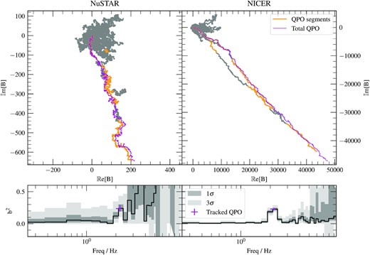
The random walk of the auto-bispectrum B(νk) for frequency bins νk which cover the frequency range νk < 10 Hz. Between 6 and 10 Hz the frequency bins are geometrically re-binned to reduce the number of bins by a factor of 4 between 6 and 10 Hz. Each grey chain has steps Bm(νk), but the segments that correspond to the instantaneous QPO frequency are highlighted in orange. All the segments that contain the QPO are summed into a purple chain. On the lower panel, the auto-bicoherence b2(νk) of each chain is given for each frequency. The grey uncertainties, and also the vertical 1σ uncertainty of the tracked QPO auto-bicoherence, are calculated from percentiles of a bootstrapped population.
The width of the feature around the QPO frequency in these plots of the bispectrum could be because the QPO frequency drifts during the observation, and therefore the frequency bin that contains the QPO frequency may not be the same for each segment. We therefore calculate b2(νqpo) using the same shift-and-add techniques as described in the previous sections. The result is marked in magenta. The vertical error bar is 1σ and again calculated by bootstrapping (as discussed in Appendix A2), and the horizontal error bar shows the frequency range covered by the QPO fundamental during the observation. We see that this new shifted-and-added bicoherence is consistent with the black stepped line, and therefore the shift-and-add does not enhance the coherence of the QPO for this particular observation. While the coherence between the QPO harmonics is statistically non-zero, it is still not unity. This can be partly explained by the presence of uncorrelated broad-band noise at the QPO frequency. However, the QPO dominates over the broad-band noise in the power spectrum for ν ≈ νqpo. It is therefore likely that ψ is not constant in time – as would be the case for a perfectly periodic oscillation – but instead varies around a well-defined mean value.
We visualize the autobispectrum in Fig. 5 with ‘jellyfish plots’ (top panels). Here, for each Fourier frequency, we plot B(ν) as a vector sum on the complex plane. The vector sum for each frequency is plotted as a grey line (and there are a total of 29 frequencies after geometric re-binning above 6 Hz). We see that this forms a random walk on the complex plane. For most frequencies, this random walk forms a blob that never gets far from the origin, indicating that the phase at ν is poorly correlated with that at 2ν. For a narrow range of frequencies, the random walk instead forms a much straighter path that extends far from the origin, indicating good correlation between ν and 2ν. The autobicoherence is a measure of how far from the origin the vector sum ends up, and the biphase is a measure of the orientation on the complex plane of the summed vector. The jellyfish plots therefore demonstrate that b2(ν) is large for ν ≈ νqpo because each segment has a similar bi-phase, and so the segments all line up well on the complex plane.
We also demonstrate how the drifting of the QPO frequency during the observation leads to the frequency bin that contains the QPO changing from one segment to another. To do this, we mark segments on the jellyfish plots that contain the instantaneous QPO frequency by colouring them orange. We see that the QPO frequency does indeed jump from one frequency bin to another. This is particularly noticeable in the NICER jellyfish plot. The magenta line instead shows the vector sum of B(νqpo) that we use to calculate b2(νqpo); i.e. we take only the segments that contain the instantaneous QPO frequency and add them on the complex plane. Consistent with the bicoherence plots, we see that the magenta line reaches a comparable distance from the origin to the two grey lines around the QPO frequency.
3.5 Reconstructed Fourier transformed spectra
We use the phase lag spectra Δ1(E) and Δ2(E) found in Section 3.2.2, the RMS spectra σ1(E) and σ2(E) found in Section 3.3.2, and the phase difference between harmonics ϕ found in Section 3.4.2 to calculate our Fourier Transformed spectra W1(E) and W2(E) using equations (2) and (3). As Wj(E) (j = 1, 2) is a complex quantity, we separate these into real and imaginary parts ℜ[Wj(E)] and ℑ[Wj(E)]. Therefore, for both of our NuSTAR and NICER observations we have calculated 4 spectra
ℜ[W1(E)], the real part of the FT spectra of first QPO harmonic,
ℑ[W1(E)], the imaginary part of the FT spectra of first QPO harmonic,
ℜ[W2(E)], the real part of the FT spectra of second QPO harmonic,
ℑ[W2(E)], the imaginary part of the FT spectra of second QPO harmonic,
giving a total of 8 FT spectra. We also have the phase-average flux-energy spectra ‘W0(E)’ for each of NuSTAR’s FMPA and FMPB, plus NICER’s, bringing our total to 11 spectra which we will simultaneously fit with the model described in the following section.
The resulting spectra are shown in Fig 6. The left-hand panel shows the phase-averaged flux-energy spectrum, W0(E), observed by NICER (black), FPMA (red), and FPMB (blue). The derived FT spectra are plotted on the right-hand side as grey and black points. The first and second harmonic (i.e. j = 1 and j = 2, or in other words the fundamental and the first overtone) are plotted, respectively, in the first and second panels from the top (as labelled), and grey and black points correspond, respectively, to the real (ℜ[Wj(E)]) and imaginary (ℑ[Wj(E)]) parts, respectively. Open circles correspond to NuSTAR and the points with no marker to NICER. Note that each part of each harmonic has only one NuSTAR FT spectrum, and not one for the FPMA and another for the FPMB. This is because the NuSTAR FT spectra are derived by extracting the subject bands of the cross-spectrum from the FPMB and the reference band from the FPMA. Both FPMs are therefore used for this single measurement.
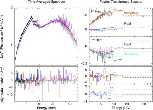
The unfolded best-fitting model, and the ratio of the data to the model, for the flux-energy spectra (left) and the harmonics of the QPO (right). The flux-energy spectra from NICER is in black, NuSTAR FPMA is in red, and NuSTAR FPMB is in blue, which have been rebinned for plotting purposes. The spectra of the real and imaginary components of the 1st QPO harmonic are in purple and orange, respectively. Likewise, the 2nd QPO harmonic components are shown in magenta and light blue. Both harmonics have the NuSTAR data points with circles and a dotted line, with the circle-less points and solid lines corresponding to NICER. The markers in grey show the real component of the FT spectra, whereas those in black show the imaginary component. The axis labels apply to both the left-hand and right-hand sides of the figure, including the units; this follows from the Fourier transformed spectra being the RMS multiplied by a unitless phase term.
4 THEORETICAL MODEL
Our model for the QPO FT calculates the X-ray spectrum as a function of QPO phase, γ, before Fourier transforming to output the real and imaginary parts of the QPO FT for the zeroth, first, and second harmonics. The model is similar to the one described in Ingram et al. (2017), but with some extra features. As in Ingram et al. (2017), we assume that the accretion flow has two components: a thin accretion disc and a corona. We assume that the disc is stationary with inner and outer radii rin and rout. We make no assumptions about the shape of the corona, but we assume that its intrinsic bolometric luminosity is constant in time, and variation in the observed flux is caused by us viewing the corona from different directions at different QPO phases.
The spectrum from the corona is described in Section 4.1. Section 4.2 describes the spectrum from the disc, which we split into a thermal component (Section 4.2.2) and a non-thermal component (Section 4.2.3).
4.1 Corona
4.2 Disc
4.2.1 Illumination of the disc
4.2.2 Thermal flux
4.2.3 Non-thermal flux
We use the model xillverCp to calculate the non-thermal component of the rest-frame emergent disc spectrum, |$\mathcal {R}(E_\mathrm{d})$|. xillverCp calculates the emergent spectrum from a passive (Tvisc = 0), constant density slab (electron number density ne = 1015 cm−3) being irradiated by an nthcomp spectrum.8 The output spectrum includes emission lines (most prominently the iron Kα line), absorption edges (most prominently the iron K edge) and the Compton hump. It also includes a quasi-thermal component caused by some fraction of the irradiating photons thermalizing in the disc, which we must ignore because we have already accounted for the thermalized illuminating flux in our blackbody component (see previous section). For xillverCp, this component peaks in the UV and is entirely below our bandpass, and so is simple to ignore.
4.2.4 Approximations
Our treatment of the rest-frame spectrum emergent from a given disc patch is very approximate. First of all, the xillverCp model that we use has ne = 1015 cm−3 hardwired, whereas we would theoretically expect the density of the disc in GRS 1915+105 to be closer to ne ∼ 1020cm−3 (Shakura & Sunyaev 1973). Secondly, the emergent spectrum is not strictly the sum of a thermal and a non-thermal component. In reality, the disc atmosphere is being irradiated from below by the intrinsic disc emission and from above by the corona, and the true emergent spectrum would need to be calculated by solving the radiative transfer equation with these boundary conditions (Reis et al. 2008). However, although high density xillver models are now available (García et al. 2016; Mastroserio et al. 2021), they only consider irradiation by the corona and ignore the intrinsic disc emission. Moreover, the xillver solutions are calculated in steady-state, and so there is no thermalization time-scale. Our treatment is therefore the best time-dependent approximation of a high density irradiated disc with strong intrinsic emission currently available.
4.3 The complete model
The total observed QPO phase-dependent specific flux, F(E, γ), is the sum of the disc and coronal contributions. Our model calculates F(E, γ) for 16 QPO phases and Fourier transforms to get the QPO FT for the zeroth (phase-average), first, and second harmonics.
Additionally, on top of the phase-dependent model described above, we include an extra xillverCp component to account for distant reflection. This component is fixed to be constant with QPO phase, as variations on the timescale of the QPO period should be strongly washed out by light-crossing delays for a distant reflector. Finally, we account for line-of-sight absorption with the model tbabs. The hydrogen absorption column NH is a free parameter, and we adopt the abundances of all other elements relative to hydrogen of Wilms et al. (2000).
5 MODEL FITS
5.1 Fitting procedure
We fit our model simultaneously to 11 spectra overall. As described in Section 3.5, these are: the flux-energy NICER, FPMA, and FPMB NuSTAR spectra, plus the first and second harmonics of the real and imaginary parts of the QPO FT measured separately by NICER and NuSTAR. Using xspec version 12.10.1f, we applied the same NICER response matrix to all 5 NICER spectra, we used the FPMA response for the flux-energy FPMA spectrum, and the FPMB response for both the FPMB flux-energy spectrum and the NuSTAR QPO FT. This is because the NuSTAR QPO FT was calculated using FPMB channels as the subject bands, and the full band FPMA light curve as the reference band. We see from Fig. 1 that the cross-calibration between NICER and the NuSTAR modules is good, except for the normalization. We account for this by multiplying our model by a floating constant, which is fixed to unity for NICER and left free for the NuSTAR FPMA and FPMB.
As we used different reference bands for the calculation of the NICER and NuSTAR QPO FTs (the full band NICER and NuSTAR FPMB light curves respectively), there is a phase difference between them caused by the phase lag between the two reference bands (see Section 3.2). We account for this by setting a phase offset ϕc for the first harmonic (the phase offset for the second harmonic is exactly 2ϕc10). Similarly to floating calibration constants employed for flux-energy spectra, we set ϕc = 0 for NICER and leave ϕc as a free parameter for NuSTAR.
In our fits, we leave the truncation radius rin as a free parameter and fix the spin to a = 0.998. While we do not necessarily expect that this choice reflects the true value of the spin (see e.g. Mills, Davis & Middleton 2021), this value enables the widest possible range of the rin parameter to be explored without it becoming smaller than the ISCO. Although the spin does affect the geodesics, this only has a very subtle effect on the spectrum compared with the location of the disc inner radius.
The full list of the free parameters in our model is included in Table 2, with those modulated with QPO phase γ in the manner of equation (11) grouped together, and are labeled in the manner of ‘Nc(γ)’. We begin by finding a global best fit through minimizing the χ2 fit statistic, before running a long Markov Chain Monte Carlo (MCMC) simulation around the best fit to explore the parameter space and understand the significance of the best fitting parameter values.
The mean and ±1σ credible interval of the posterior distributions of each parameter, calculated with a MCMC. The two parameters marked with † are those solely relating to the phase-constant reflected component assumed to come from a distant reflector. The ‘Asym.’ parameters are those that govern the asymmetric illumination profile. The FPMA and FPMB norm parameters are floating calibration constants.
| Parameter | Unit | Chain mean | Description | |
|---|---|---|---|---|
| NH | 1022 | 6.8 ± 0.3 | tbabs col. density | |
| Γ(γ) | A1Γ | 0.04 ± 0.01 | Photon index | |
| A2Γ | 0.05 ± 0.02 | |||
| ϕ1Γ | cyc | 0.42 ± 0.04 | ||
| ϕ2Γ | cyc | 0.13 ± 0.03 | ||
| Γ | 1.93 ± 0.01 | |||
| kTe(γ) | A1e | keV | 38. ± 13. | Electron temp. |
| A2e | keV | |$19. ^{+8. }_{-9. }$| | ||
| ϕ1e | cyc | 0.44 ± 0.04 | ||
| ϕ2e | cyc | 0.97 ± 0.03 | ||
| kTe | keV | |$57. ^{+9. }_{-10. }$| | ||
| log ξ† | 2.5 ± 0.2 | Ionization of dist. refl. | ||
| norm† | 10−3 | 0.7 ± 0.2 | Normalization of dist. refl. | |
| AFe | AFe⊙ | 7. ± 1. | Accreting Fe abundance | |
| Incl. | deg | |$75.1^{+0.5}_{-0.3}$| | Inclination of source | |
| rin | rg | |$1.43^{+0.01}_{-0.02}$| | Inner truncation radius | |
| q1 | |$13.6^{+0.8}_{-0.7}$| | Inner emissivity index | ||
| rbr, 1 | rin | 2.4 ± 0.5 | 1st break radius | |
| q2 | |$4. ^{+5. }_{-4. }$| | Outer emissivity index | ||
| rbr, 2 | rbr, 1 | |$14. ^{+11. }_{-10. }$| | 2nd break radius | |
| Asym. | A1 | 0.5 ± 0.3 | Asymmetric illumination | |
| A2 | 1.3 ± 0.7 | |||
| Φ1 | cyc | 0.9 ± 0.1 | ||
| Φ2 | cyc | |$0.99^{+0.06}_{-0.05}$| | ||
| fR(γ) | A1f | 0.3 ± 0.1 | Reflection fraction | |
| A2f | 0.3 ± 0.1 | |||
| ϕ1f | cyc | 0.45 ± 0.05 | ||
| ϕ2f | cyc | 0.94 ± 0.05 | ||
| fR | |$0.96^{+0.08}_{-0.09}$| | |||
| log ξmax | |$4.26^{+0.08}_{-0.09}$| | Max radial ionization | ||
| Δγ | cyc | 0.17 ± 0.07 | Thermalization phase lag | |
| kTv, max | keV | 0.24 ± 0.05 | Max radial viscous heating | |
| kTi | keV | 0.64 ± 0.04 | Heating from irradiation | |
| Nd | 25. ± 11. | Disc normalization | ||
| Nc(γ) | A1N | 1.2 ± 0.2 | Coronal normalization | |
| A2N | 0.8 ± 0.3 | |||
| ϕ1N | cyc | 0.96 ± 0.03 | ||
| ϕ2N | cyc | 0.70 ± 0.03 | ||
| Nc | 5.8 ± 0.2 | |||
| FMPA | 0.944 ± 0.001 | NuSTAR FMPA norm. | ||
| FMPB | 0.951 ± 0.001 | NuSTAR FMPB norm. | ||
| ϕc | cyc | 0.018 ± 0.004 | NuSTAR phase offset | |
5.2 Results
Our global best fit, which is shown in Fig. 6, has χ2 = 3374.6 for 3179 degrees of freedom (DoF). The phase-average flux-energy spectrum in the upper-left of the figure shows the good fit, especially to the Fe Kα line. The right-hand side of the figure shows the real and imaginary parts of the FT spectra of the first two harmonics. The features of these spectra are markedly less intuitive, and so we rely on analysis of the parameter space to understand the model fit. As the distant reflector is constant on the QPO timescale, the FT spectra do not include this component. However, as they are normalized to the observed flux (see equation 3), the absorption column does matter and therefore is included.
We explored parameter space by running a long MCMC simulation with 120 walkers which each run for 250 000 steps from an initial distribution based on the covariance matrix of the best fit. Every parameter had a uniform prior with bounds considerably far from the range required, except where parameters must be non-negative.11 We burn the first 50 000 steps of each walker, enough to ensure that the Geweke convergence diagnostic (Geweke 1992) is within ±0.3 for every parameter and we therefore only consider steps where the MCMC has converged. Finally, we thin the MCMC down, only taking every 100th step from each walker. We show the posterior means and 1σ credible intervals from the MCMC in Table 2.
In Fig. 7, we visualize our results by reconstructing parameter modulations from the thinned chain. For each step in the chain (there are |$240\, 000$| steps altogether), we use the parameter values corresponding to that step in order to calculate each of the 7 quantities plotted in Fig. 7 as a function of QPO phase. From these |$240\, 000$| functions of QPO phase, we create a 2D histogram, which we plot as a probability map (black represents the largest probability).
Panels 2-5 in Fig. 7 show the parameters that are allowed to vary with QPO phase via a sum of sinusoids (e.g. equation 11); from top to bottom: fR(γ), Γ(γ), kTe(γ), and Nc(γ). We consider the posterior distributions in Fig. D2, and we see that all the parameter modulations are significant to at least 3σ, with Nc(γ) likely at a much higher significance. The bottom two panels in the figure are log ξmax(γ) and kTirr(γ). The modulations in these parameters are not free to vary in our fit, they are instead calculated from Nc(γ) and fR(γ) (see equations 19, and 21). These are remarkably constant with QPO phase, as they are both ∝Nc(γ)fR(γ) (neglecting the phase shift Δγ), whose modulations are approximately out of phase.
The top panel is iron line centroid energy. In order to determine this, we first calculate the observed QPO phase-dependent reflection spectrum (equation B1) assuming a δ −function iron line in the disc restframe (i.e. I(Ed) = δ(Ed − 6.4keV)) and then calculate the centroid energy of the resulting QPO phase-dependent line profile (using Equation 7 from Ingram et al. 2017). Any modulations of this function with QPO phase are caused entirely by QPO phase dependence of the emissivity function ϵ(r, ϕ, γ), which in turn is driven exclusively by the asymmetry parameters A1 and A2. We see that the line centroid energy is strongly modulated with QPO phase, implying that the emissivity function is required by the fit to vary with QPO phase. We show the posterior distribution of the asymmetry parameters from the MCMC in Fig. 8. The point A1 = A2 = 0 lies outside of the 2σ contour (in red), therefore we are able to reject the axi-symmetric null-hypothesis of A1 = A2 = 0 at the 2σ significance level.
We show the QPO phase-dependent spectrum of the best-fitting model in Fig. 9, without the line-of-sight absorption and distant reflector. We see large changes in spectral shape over the course of the 8 QPO phases pictured, most obviously the change in continuum normalization Nc(γ) following the same trend as shown in Fig. 7. As the normalization of the reflection spectrum is broadly constant with phase, its key features of the Fe Kα and Compton hump are less pronounced when Nc(γ) is larger. The temperature of the Compton hump itself does change, most noticeably at its lowest value of γ ≈ 1/4 cycles.
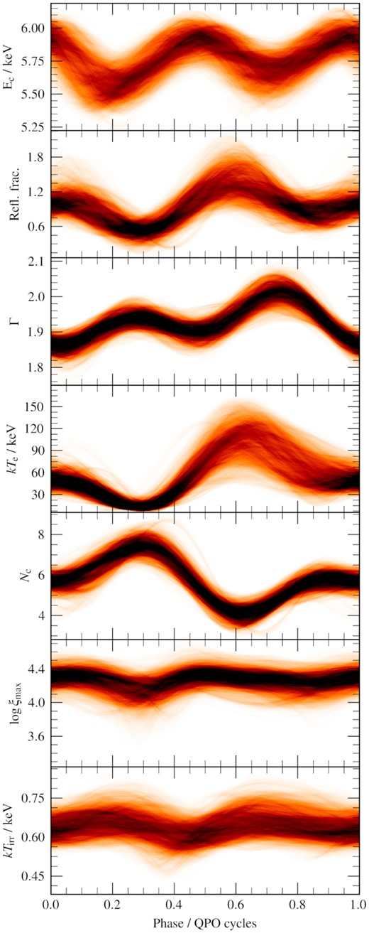
Curves produced from the parameters from steps in the MCMC. The iron-line centroid energy Ec was calculated from the varying illumination profile, assuming a rest-frame δ −function profile (see text for details). The reflection fraction, Γ, kTe, and Nc are the modulations straight from their parameters in the model, whereas log ξmax and kTirr are calculated from the irradiating flux, as described in the text.
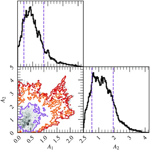
A1 and A2 contour based around the MCMC. The 1σ, 2σ, and 3σ credible intervals are shown as contours (purple, orange, and red), with the blue lines highlighting the values at the best fit. Within the 1σ contour the density is shown as a grey-scale 2D-histogram. Outside the 3σ contour individual points are shown as grey points. The marginalized histograms also show the ±1σ credible interval with purple dashed lines.
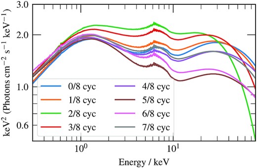
The QPO phase dependent component of our best-fitting model; without line-of-sight absorption or the distant reflector component. This is comprised of the nthcomp cut-off power law; a ray-traced xillverCp reprocessed spectrum with relativistically smeared atomic features (5–8 keV) and Compton hump (≳20 keV); plus a blackbody thermal spectrum at ≲2 keV. This shows the model at 8 phases, although 16 phases are used for the calculation of the Fourier transformed components.
When we consider the covariance between the modulated variables (see Fig. D1), we see the strongest correlation is between the reflection fraction fR and continuum normalization Nc. Interestingly, the phase-averaged values are negatively correlated, however, the size and phases of the modulations are positively correlated. We can see in Fig. 7 that these modulations are also in antiphase, and so their modulations work against each other to keep the incident flux on to the disc approximately constant, as can be seen in the waveforms of log ξmax(γ) and kTirr(γ).
We find that the posterior mean of the phase lag Δγ, intended to represent the time it takes photons to thermalize in the disc atmosphere, is Δγ ≈ 0.17 QPO cycles. Fig. 10 shows the posterior distribution of Δγ from the MCMC, including a conversion from QPO cycles to time lag for a QPO frequency of νQPO = 2.2 Hz. This phase lag can be seen in the bottom two panels of Fig. 7, since the dip in kTirr(γ) occurs ∼0.17 QPO cycles after the dip in log ξmax(γ). It can also be seen in Fig. 9: e.g. the orange line for QPO phase =0.125 cycles corresponds to a peak in iron line centroid energy but not to a peak in disc peak temperature. Converting Δγ to a time lag gives ∼75 ms, which is rather large. This large value is possibly due to model systematics, since if the thermalization time-scale really were this long, then we would see much longer thermal reverberation lags than have been observed (e.g. Uttley et al. 2011; Kara et al. 2019).
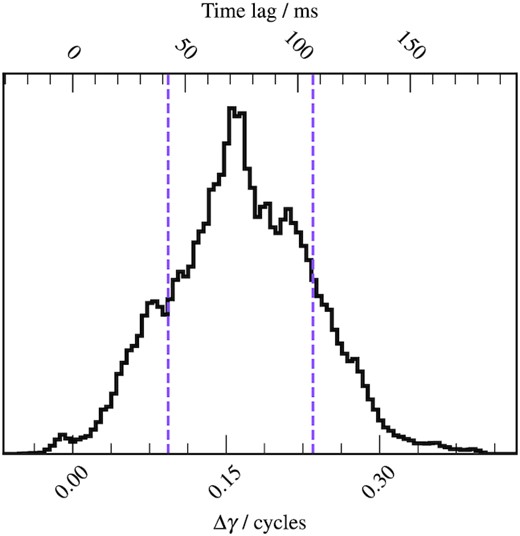
Histogram of Δγ from the MCMC, with the corresponding time-lag for a frequency of 2.2 Hz. The ±1σ credible interval is outlined with purple dashed lines.
6 DISCUSSION
We have conducted a phase-resolved spectral analysis of an ∼2.2 Hz QPO from GRS 1915+105 observed simultaneously by NICER and NuSTAR. We found that the continuum normalization Nc(γ), photon index Γ(γ), reflection fraction fR(γ), and electron temperature kTe(γ) are all required to be modulated with QPO phase to >3σ confidence, plus we rule out that the asymmetric illumination parameters A1 = A2 = 0 at the 2σ confidence level. Alongside this, we found a small inner truncation radius rin, and a large thermalization phase lag Δγ. We now discuss the implications of these results.
6.1 Comparison with H1743−322
We compare our results with the previous similar study of an ∼0.25 Hz type-C QPO in H 1713-322 by Ingram et al. (2017) (hereafter I17). The first thing to note is the strikingly similar profiles of the continuum normalization, Nc(γ) (compare our Fig. 7 with the fig. 5 in I17), which is a proxy for the X-ray flux. Whereas the fractional amplitude of the Nc(γ) modulation is larger here, the profiles – and therefore the QPO waveforms – are similar for the two observations, despite the QPO frequencies being very different. This similarity is confirmed by the measured phase difference between harmonics, ψ, which defines the QPO waveform (Ingram & van der Klis 2015). Here, we measure ψ/π ≈ 0.2 for the NuSTAR observation, whereas the NuSTAR measurement for H 1743-332 was ψ/π ≈ 0.3 (Ingram et al. 2016). This indicates that the Nc(γ) modulation for H 1743-322 should be similar to what we measure here for GRS 1915+105 but with the peak slightly delayed, which can indeed be seen in the Nc(γ) profiles. It is perhaps surprising that the QPO waveform of the two observations is so similar given that Ingram & van der Klis (2015) observed it to change dramatically between two RXTE observations of GRS 1915+105 with QPO frequencies of ∼0.5 Hz and ∼2.25 Hz. Fig. 5 (right-hand panel) in de Ruiter et al. (2019) reveals that this is because ψ reduces more steeply with QPO frequency in GRS 1915+105 than it does in H 1743−322, such that its value for GRS 1915+105 at νqpo ∼ 2 Hz is close to the corresponding value for H 1743-322 at νqpo ∼ 0.2 Hz. The measurement of ψ presented here is therefore consistent with the trends found by de Ruiter et al. (2019). Beyond the overall shape, we also see a much wider spread in our Nc(γ) histogram than that presented by I17. This is because we are now using a much more flexible model than in previous work, including modulations in kTe, and so it is better able to compensate when Nc(γ) deviates from its best-fitting functional form.
As for the modulation in iron line centroid energy, Ec(γ), we see a strong second harmonic (evidenced by there being two maxima per QPO phase as opposed to one) both in our observation and in the I17 analysis of H 1743−322. This property was also previously observed for GRS 1915+105 by Ingram & van der Klis (2015), albeit with a low statistical significance. We however see that the phase of the Ec(γ) modulation is shifted here with respect to the H 1743−322 observation: here, the maxima in Ec occur at QPO phase γ ∼ 0 and 0.5 cycles, whereas for H 1743−322 they occur at γ ∼ 0.2 and ∼0.7 cycles. A similar evolution in the Ec(γ) waveform is seen between the two GRS 1915+105 observations presented in Ingram & van der Klis (2015): their Ec(γ) waveforms for νqpo ∼ 0.5 Hz and νqpo ∼ 2.25 Hz QPOs are respectively similar to the ∼0.2 Hz QPO in H 1743−322 and the ∼2.2 Hz QPO in GRS 1915+105 presented here. This gives a potential hint that the phase of the line centroid energy modulation evolves systematically with QPO frequency, as is the case for the flux modulation (de Ruiter et al. 2019). We additionally see that the Ec(γ) modulation presented here has a lower mean and a higher amplitude than that presented by I17. This is consistent with the disc inner radius reducing as the QPO frequency increases: the mean is reduced by increased gravitational redshift and the amplitude is increased by faster orbital motion closer to the BH.
I17 found modulations of the reflection fraction, fR, and power-law index, Γ, to have 3.52σ and 0.95σ significance, respectively, whereas here we find both modulations to have >3σ significance. As the reflected spectrum is spectrally harder than the directly observed spectrum, an increase in spectral hardness can be caused either by a reduction in Γ or an increase in fR. Whereas the Γ(γ) and fR(γ) modulations presented by I17 are broadly in phase, suggesting they somewhat compensate for each other. Here, we find they are broadly in antiphase suggesting they are both contributing to the modulation of the spectral hardness.
6.2 Asymmetric illumination profile
Our model requires an asymmetric illumination profile with A1 = 0.5 ± 0.3 and A2 = 1.3 ± 0.7 which is consistent with two, non-identical bright patches rotating around the disc with QPO phase. The QPO phase dependence of the iron line profile could, to some extent, be reproduced by changes in the ionization state of the disc atmosphere, which would cause changes in the shape and centroid energy of the iron line in the rest-frame reflection spectrum (since e.g. Compton broadening of the line increases with the number of free electrons and higher order ions are more tightly bound and therefore produce higher energy fluorescence lines). The parameters that affect the shape of the rest-frame reflection spectrum and are modulated with QPO phase in our model are Γ, kTe, and log ξ. All three affect the ionization state of the disc, with larger kTe, larger log ξ, and smaller Γ increasing the number of irradiating photons with a high enough energy to ionize neutral iron (E > 7.1 keV). In the model employed by I17, only Γ was allowed to vary with QPO phase, whereas here we also allow kTe and log ξ to vary, with log ξ tied to the illuminating flux. We also note that here we employ a radial log ξ profile, whereas only a single ionization parameter was used for the entire disc in I17. Given the flexibility of our model and the conservative nature of our analysis, we find that the asymmetric illumination parameters A1 and A2 are only required to be non-zero at >2σ confidence level.
Such an asymmetric, QPO phase-dependent illumination pattern is naturally expected if the corona illuminating the disc is precessing (Ingram & Done 2012). Alternatively, precession of the disc itself (i.e. precession of the reflector and not the illuminator) could potentially explain our data (Schnittman et al. 2006). However, disc precession is not expected theoretically (Bardeen & Petterson 1975; Liska et al. 2019) unless the frame dragging effect is strong enough to tear the disc into a number of discrete, independently precessing rings (Nixon & King 2012; Liska et al. 2021). Such a configuration could in principle cause QPOs if the number of independent rings is small enough to produce a coherent oscillation. However, disc tearing requires a large misalignment between the binary and BH rotation axes, which is expected to be rare since the biggest natal kicks, which would produce the largest misalignments, are also the most likely to completely disrupt the binary system (Fragos et al. 2010). This is in contrast to the near-ubiquity of Type-C QPOs. Line profile modulations could also result from c-mode disco-seismic waves (e.g. Kato & Fukue 1980; Kato 2001). However, this would not explain the QPO being much stronger in the Comptonized spectrum than in the disc spectrum, and the line profile variations produced by c modes are quite subtle compared with what we observe (see e.g. fig. 5 in Tsang & Butsky 2013), due to the c-mode oscillation only occurring in a narrow range of disc radii. The spiral waves of the AEI model are also consistent with the asymmetric illumination profile we measure here (Varniere, Rodriguez & Tagger 2002). However, the AEI model is not consistent with a reflection fraction modulation, which we measure with >3σ significance, whereas the precessing corona model is.
A new QPO diagnostic will soon be available in the form of X-ray polarization. Whereas the precession model predicts the polarization degree and angle to be modulated on the QPO period (Ingram et al. 2015), alternative models such as the AEI do not. After its launch later this year, the Imaging X-ray Polarimetry Explorer (IXPE) should be capable of detecting QPOs in the X-ray polarization properties in a long exposure observation of a bright X-ray binary, as long as high inclination X-ray binaries turn out to be moderately polarized (|$\gtrsim 4{{\ \rm per\ cent}}$|; Ingram & Maccarone 2017).
6.3 Inner radius
Our best-fitting model also requires a small disc inner radius of |$r_\text{in}\simeq 1.43^{+0.01}_{-0.02}~\text{r}_\text{g}$|, where rg = GM/c2. While this is compatible with previous reflection spectroscopy results (Miller et al. 2013; Zhang et al. 2019; Shreeram & Ingram 2020), it does not leave much room for a corona to precess within this truncation radius in order to give rise to the best-fitting asymmetric illumination profile. Moreover, it is very much incompatible with the precession being specifically at the Lense–Thirring precession frequency, which requires rin ≈ 41 rg to reproduce a QPO frequency of ≈2.2 Hz.12
We therefore first consider if our analysis has returned an artificially small disc inner radius due to the use of an inadequate continuum model. Including a second, softer power-law component can yield a larger truncation radius in fits to the flux-energy spectrum, since the new component takes the place of the broad red wing characteristic of small rin (Yamada et al. 2013; Mahmoud & Done 2018; Mahmoud, Done & De Marco 2019; Zdziarski et al. 2021a,b). Such a treatment could therefore yield a larger truncation radius in our analysis if our measured disc inner radius is driven primarily by the time-averaged iron line profile. However, our analysis is also sensitive to the QPO phase-dependence of the iron line profile. For a large truncation radius, the red wing can dominate over the blue wing when the receding disc material is illuminated, whereas for a small truncation radius the variability is entirely in the blue wing because the red wing is always suppressed by gravitational redshift (Ingram & Done 2012; You et al. 2020).
By excluding the iron line from the flux-energy spectrum, but leaving in those bands for the Fourier transformed spectra, we are able to investigate whether this small rin is required by only the phase-average spectrum or also by the QPO phase dependence of the spectrum. We therefore run a new phase-resolved fit in which we ignore the 5–8 keV data from the flux-energy spectrum but leave in those bands for the Fourier transformed spectra. For this new fit, the measured rin value will not be driven by the time-averaged shape of the iron line, but by how its shape changes throughout the course of each QPO cycle. This new fit also returns a small disc inner radius of |$r_\text{in}=1.49_{-0.04}^{+0.03}~\text{r}_\text{g}$|. It is still possible that including a more complex continuum could allow for a slightly larger rin, but this would add many more degrees of freedom to our already extremely flexible model.
Our fits therefore indicate (although not definitively) asymmetric illumination of a disc extending to a very small inner radius. It could be that the corona is not radially extended but instead a vertically extended structure, such as a precessing jet (Kalamkar et al. 2015; Stevens & Uttley 2016; Kylafis, Reig & Papadakis 2020) (if the jet base is sufficiently X-ray bright; Fender et al. 1999; Markoff et al. 2005). GRMHD simulations show that jet precession can be induced by the frame dragging effect (Liska et al. 2018), but only so far in the presence of a thick disc. Indeed, our best fitting model includes a very strongly peaked emissivity function, with |$q_1=13.6^{+0.8}_{-0.7}$| for disc radii r < 3.3 ± 0.6 rg. This emissivity profile is roughly compatible with one created by a vertically extended corona raised slightly above the thin accretion disc (Wilkins & Fabian 2012).
It is, however, unclear exactly how the frame dragging effect could drive such slow precession for such a small disc inner radius. Perhaps the corona is vertically extended with the density increasing with distance from the BH. This weighting of the density to larger distances from the BH will slow down precession compared with a precessing ring at the same rin. The torque exerted on the corona by the outer disc, which is not currently considered in calculations of the precession frequency, will also slow down precession. It is not, however, clear whether or not these two effects are sufficient to solve the discrepancy we find here. Even if they are, and Lense–Thirring precession really is the true type-C QPO mechanism, their presence will make it much more difficult to infer BH mass and spin from the QPO frequency than previously hoped. A clear counter-argument to this point is provided by the QPO triplet in GRO J1655−40, the frequencies of which can be explained very well by the relativistic precession model, returning a precise mass prediction that agrees with the dynamical value (Motta et al. 2014; Fragile, Straub & Blaes 2016). This result instead argues that our very small disc inner radius is instead the result of modelling systematics such as employing an overly simplified continuum, as discussed above.
It is important to note that all well-studied QPO models in the literature assume that the QPO frequency increases during the state transition primarily due to the disc inner radius moving inwards (Ingram & Motta 2019). There is therefore no published QPO model that can reproduce our observed QPO frequency for our measured disc inner radius without significant modification.
6.4 Misalignment
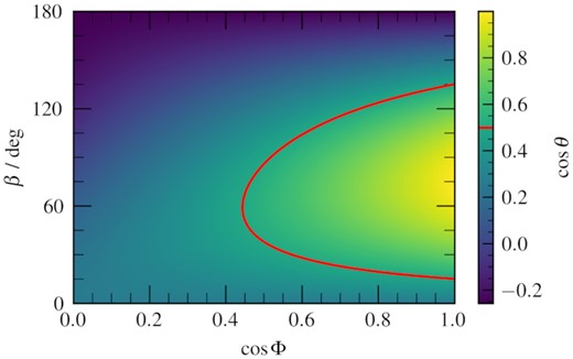
The BH spin axes inclination θ, for different values of misalignment between it and the disc, for the different values of disc azimuthal angle Φ of the misalignment. The red line highlights θ = 60○, the observed inclination large-scale jet, which could be assumed to be aligned with the BH spin-axis.
This misalignment will greatly influence the BH spin inferred from disc continuum fitting in the soft state. In the most recent such analysis of GRS 1915+105, Mills et al. (2021) report a best fit of a ≈ 0.86 (risco(a) = rin ≈ 2.57 rg), with the very high spin required by reflection spectroscopy measurements (including our own) also within uncertainties. However, they assume a completely aligned system, with the binary inclination δ equal to the disc inclination i equal to the jet inclination θ. Ignoring relativistic corrections, the disc inner radius inferred from disc fitting is |$r_\text{in} \propto D / (M \sqrt{\cos i})~\text{r}_\text{g}$|, and so adopting i = 75○ in place of i = θ = 60○ (but still assuming δ = θ and D = 8.6 kpc) would instead give rin ≈ 3.63 rg. The inferred inner radius is pushed even further out if we set δ = i as is assumed in the precession model (Ingram et al. 2009; Ingram et al. 2015), since the BH mass is related to the binary mass function f(M) as M ∝ f(M)/sin 3δ. For δ = i = 75○ and still assuming D = 8.6 kpc, the inner radius becomes rin ≈ 5 rg, which is incompatible with our measured value of rin ≈ 1.4 rg. If we instead assume that δ is unknown, we find that for i = 75○ and D = 8.6 kpc the disc continuum fitting inner radius is equal to our value if δ ≈ 39○, implying a BH mass of M ≈ 32 M⊙ which is much greater than the dynamical measurement of 10.1 ± 0.6 M⊙ (Steeghs et al. 2013).
We note, however, that a thin misaligned disc is expected to form a so-called Bardeen–Petterson configuration (Bardeen & Petterson 1975), whereby the outer and inner regions align, respectively, with the binary and BH spin axes. GRMHD simulations show that the transition from misaligned to aligned can be close to the BH (r ∼ 6 rg; Liska et al. 2019), but still further out than our very small inner radius of rin ∼ 1.4 rg. In contrast, our simplified model only considers a planar disc. It could be that failing to account for a more realistic warped disc geometry has introduced a bias into our measurement of i, or even of rin.
6.5 Biases in the phase-averaged spectrum
The shape of our best-fitting phase-resolved spectrum changes dramatically with QPO phase (Fig. 9). These non-linear variations over each QPO cycle may cause biases in analyses that only fit a steady-state model to the time-averaged flux-energy spectrum. Following I17, we investigate these potential biases in Fig. 12 by plotting the phase-averaged spectrum of our best fitting phase-resolved model (black) alongside the spectrum calculated by setting all modulated parameters to their phase-averaged values (red), as well as the percentage difference with respect to the phase-averaged model (bottom panel). We see that the difference between the two spectra is only |$\sim 1{{\ \rm per\ cent}}$| in the ∼5–20 keV region, but is much larger at lower and higher energies, indicating that ignoring spectral variability does indeed cause a bias. We investigate further by fitting the observed flux-energy spectrum with a steady-state model (blue lines), which reproduces the phase-averaged model very well (except for a narrow feature at ∼6.7 keV, which NICER and NuSTAR cannot resolve, but future missions such as ATHENA will be able to). The parameters of the new fit are consistent with those of the phase-resolved model except kTirr, kTvisc, and kTe are all cooler and the disc normalization is larger. We therefore conclude that these parameters are biased by spectral variability, but not other key parameters such as i and rin.
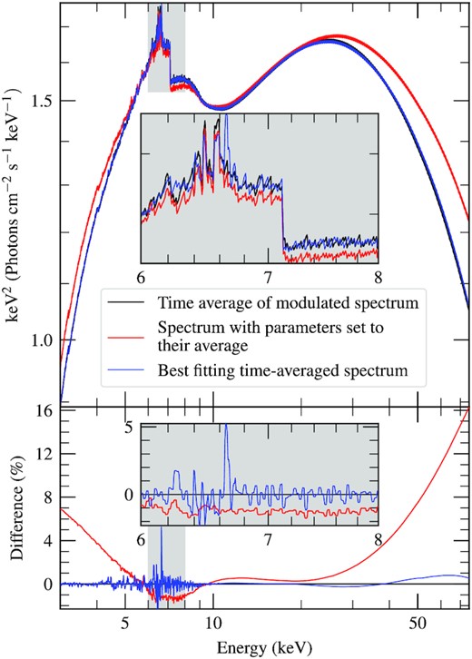
Top: The best-fitting flux-energy specturm (black); the same however with all the modulations turned off so each parameter is set to its phase-average value (red); the best-fitting model when there is no phase-dependant parameter modulations or changing illumination profile (blue). Bottom: The percentage difference between the two. The grey inset panels show a 5–10 keV zoomed-in version of their respective lines, with the corresponding areas of the main graph also highlighted in grey.
6.6 Thermalization lags
In our model we include a phase lag, Δγ, between variations in the illuminating flux and corresponding variations in disc heating. This is to allow for the finite time it takes for incident radiation to thermalize in the disc atmosphere. This time-scale is poorly understood theoretically, but is surely longer than the corresponding time-scales for other processes such as fluorescence and scattering, which are almost instantaneous (García et al. 2013b). Leaving Δγ as a free parameter in principle enables us to empirically measure this thermalization time-scale. Our best-fitting value of |$\Delta \gamma = 0.15^{+0.06}_{-0.05}$| cycles corresponds to a time-lag of |$\sim 70^{+26}_{-25}$| ms given that the QPO frequency is 2.2 Hz, which is much larger than expected. This very long thermalization time delay is incompatible with observations of ≲1 ms soft lags in e.g. MAXI J 1820+070 (Kara et al. 2019) and GX 339-4 (Uttley et al. 2011), and so it is very likely that the Δγ parameter is accounting for some other oversimplification in our model. This is perhaps not surprising, since our prescription is so simple. For instance, we assume a single thermalization delay, whereas in reality it is likely dependent on disc radius (Frank et al. 2002) and on ionization parameter (which varies with both disc radius and azimuth in our model). Moreover, in reality there will be some smearing such that e.g. very fast fluctuations in the irradiating flux will not be efficiently transferred into fluctuations in disc temperature, which we currently completely ignore.
In the context of the precessing corona model, there are a number of effects that we do not account for here which would lead to modulations of the observed disc temperature. For instance shadowing: the precessing corona and/or jet obscuring different disc azimuths at different precession phases leading to a variation in the shape of the overall observed disc spectrum. We also note that in the precessing corona model, the misalignment between the disc and BH spin axes, β, remains constant but as the corona precesses around the BH spin axis its misalignment with the disc axis varies between 0 and 2β (e.g. Ingram et al. 2015). This would lead to the illumination profile being axisymmetric once per QPO cycle, which is not accounted for by the illumination profile employed here. There are also potential sources of systematic error in our spectral model. For instance in the xillverCp grids that we use, the seed photon temperature is hardwired to kTbb = 0.05 keV, whereas the seed photon temperature of the nthcomp component in our model varies with QPO phase. Finally, we ignore light crossing delays in our parametrization of the disc illumination profile, which can be the order of milliseconds for reflection from r ∼ 10s of rg. This is |$\lesssim 1{{\ \rm per\ cent}}$| of the ∼0.45s QPO period, but will become increasingly important for the study of QPOs with increasingly higher centroid frequency.
7 CONCLUSIONS
We have conducted a phase-resolved spectral analysis of a Type-C QPO in a simultaneous NICER and NuSTAR observation of GRS 1915+105. We used a QPO phase-resolving technique, following Ingram et al. (2016) but significantly improved on their work, by including a QPO frequency tracking algorithm that makes it possible to analyse long observations over which the QPO frequency may change, and using the bispectrum to constrain the phase difference between QPO harmonics which has the advantage of enabling a proper Poisson noise correction. We have also used a significantly more advanced version of the Ingram et al. (2017) tomographic model with which to fit the phase-resolved spectra in the Fourier domain. Our new model allows more parameters to be simultaneously modulated and includes self-consistent modulations to the ionization parameter and disc heating due to irradiation.
Our fit requires the asymmetric illumination parameters A1 and A2 to be >0 with >2σ confidence. Similar to the results of I17 for H 1743−322, this is consistent with that expected for precession of the illuminator, but our measurement has only moderate statistical significance. We also detect a >3σ significant modulation of the reflection fraction, indicating that the geometry of the inner accretion disc changes systematically with QPO phase. We inferred a high disc inclination (i ≈ 75○), which implies that the disc is misaligned with the previously observed jet ejections (θ ≈ 60○). This is consistent with the precessing corona model for the QPO (Ingram et al. 2009). However, our fit also favoured a small disc inner radius, which requires the corona to be vertically rather than radially extended and is inconsistent with the precession frequency being set purely by the frame dragging effect. We discussed some possible effects that could slow down Lense–Thirring precession compared with the simplest prediction. We note that no QPO model currently in the published literature can reproduce the observed QPO frequency for our measured disc inner radius (Ingram & Motta 2019). Therefore, either our measured radius is affected by modelling systematics – such as the continuum in reality being more complex than we assume – or new or modified theories must be developed to model the QPO frequencies.
We also recovered a large thermalization delay, which implies that irradiating photons take ∼70 ms to thermalize in the disc atmosphere. We argued that this is infeasibly large and discussed potential sources of systematic error that could be contributing to the measurement.
We compared this analysis and the work of Ingram et al. (2016, 2017) on H 1743-332, and in particular note they both show a strong second harmonic in the modulation of the iron line centroid energy Ec(γ). We found hints that the Ec(γ) modulation evolves systematically with QPO frequency, as would be expected for example if the disc inner radius reduces as the QPO frequency increases. Further work is required to test this hypothesis.
ACKNOWLEDGEMENTS
AI, EN, and DA acknowledge support from the Royal Society. MK thanks the support from NWO Spinoza. We acknowledge the following packages for python3 (Van Rossum & Drake 2009) which were used in this analysis:
numpy (Harris et al. 2020).
scipy (Virtanen et al. 2020).
matplotlib (Hunter 2007).
Corner (Foreman-Mackey 2016).
This research has made use of data, software and/or web tools obtained from the High Energy Astrophysics Science Archive Research Center (HEASARC), a service of the Astrophysics Science Division at NASA/GSFC and of the Smithsonian Astrophysical Observatory’s High Energy Astrophysics Division.
We thank the anonymous referee for their insightful comments.
DATA AVAILABILITY
The observational data analysed here are all publicly available via HEASARC. We will share our model upon reasonable request to the corresponding author.
Footnotes
MJD 58277−58278.
The average RMS is often reported as 〈σj(E)〉, with an additional multiple of |$\sqrt{2}$| included in equation (1). This is to make explicit that the average RMS of a sine-wave is |$1/\sqrt{2}$|. For simplicity we neglect this, keeping in mind our model is normalized to expect the average RMS.
Apart from the bin at the Nyquist frequency which is a χ2 distribution with only a single degree of freedom, but this bin was ignored in our calculations for simplicity.
The difference in the scatter of QPO frequencies between the lower count rate NuSTAR and higher count rate NICER data suggests that this is noise in the measurement rather than intrinsic short time-scale changes.
As we are using the FFT, we actually use discrete frequency bins νk = k/T.
We note this method can find the phase-difference between any doublet harmonics, e.g. also between the 2nd and 4th harmonics. In much the same way, higher order polyspectra could be used to find the phase difference between other harmonics, e.g. the trispectrum could be used to find the phase difference between the 1st and 3rd harmonics.
Note that we do not employ a stress free inner boundary condition, which is appropriate if the corona is located inside of the disc, providing a torque.
Note that xillverCp is calculated for an irradiating spectrum given by nthcomp with the seed photon temperature hardwired to kTbb = 0.05 keV, whereas we allow our continuum spectrum to have a seed photon temperature that is free to vary with QPO phase.
Computing the ionization in this way does mean the rest-frame reflection spectrum is non-uniform across the disc, thus is formally |$\mathcal {R}(E_\mathrm{d},r,\phi ,\gamma)$|.
This follows as the phase of each harmonic in every energy band is measured in reference to the phase of the first harmonic in the reference band. ϕc is the phase offset between the first harmonics in the reference band between the two instruments, and the same offset is 2ϕc when instead measured at frequency of the second harmonic. See Appendix C for the derivation.
The amplitude ‘A’ parameters of phase-modulated quantities are such examples, including the asymmetry parameters A1 and A2.
This of course might not be correct, as jets have been observed to precess as in e.g. Miller-Jones et al. (2019).
As here for normalization consistency, we consider light curve segments measured in photon counts, as opposed to the count-rate.
As an example, if M = 5, with segments labelled ‘A’,‘B’,‘C’,‘D’, and ‘E’ we would use 1000 random draws such as ‘ABAAD’, ‘EECDC’, and so on.
However in the region of low signal/noise, the Poisson correction we make can push an estimate below 0, see Appendix A2 for details.
REFERENCES
APPENDIX A: PHASE DIFFERENCE FROM BISPECTRUM
A1 Treatment of Poisson noise in the bispectrum
The ‘jellyfish plots’ in Fig. 5 are corrected for Poisson noise and deadtime effects. Failing to correct for these effects introduces an instrumental component into the real part of the bispectrum, which presents itself as a general ‘drift’ of the random walks along the positive real axis. In turn, this reduces the measured bi-phase from the true value.
A2 Jellyfish bootstrapping
We use a bootstrapping method to calculate the uncertainties in the bispectrum for our determination of the phase-difference between the QPO harmonics.
Each observation has already been split up into M segments, so we draw from this (with replacement) a sample of M segments, 1000 times.15 Therefore, each of these 1000 random draws is the same ‘length’ as the original observation. We then calculate the bispectrum for each of these samples. When performing the QPO tracking, we ensure to use the QPO frequency corresponding to the segment’s true time.
As b2 is restricted to be positive,16 we show the range corresponding to the ±1σ and ±3σ quantiles in Fig. 5.
To ensure we do not fall foul of any issues relating to the cyclic nature of the biphase, to calculate the error on the QPO phase difference we take the measurement from each 1000-segment sample. For these values, we phase-wrap them so each lies within π rad of the true measurement and then report the standard deviation on these values as our uncertainty.
APPENDIX B: MODEL DETAILS
B1 Ray tracing
B2 Model normalization
APPENDIX C: PHASE OFFSETS WITH DIFFERENT REFERENCE BANDS
APPENDIX D: MCMC CORNER PLOTS OF MODULATED PARAMETERS
This appendix contains corner plots of some of the parameters from the MCMC. Fig. D1 shows the phase average, and the 1st harmonic and 2nd harmonic amplitudes of the modulated parameters compared with each other. Fig. D2 shows the 1st and 2nd harmonic amplitudes for each of the modulated parameters, from which we can see how significantly away from (0,0) the parameter is, which would correspond to that parameter not being modulated.
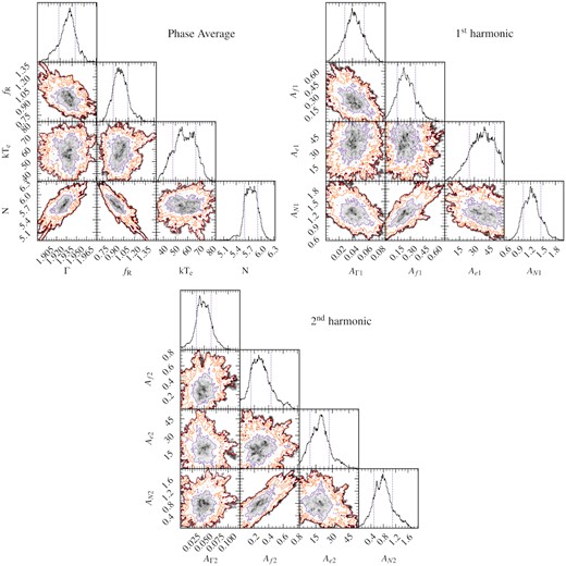
Corner plots from the MCMC of the modulated parameters within the model. The purple, orange, and red lines show the 1σ, 2σ, 3σ credible intervals, respectively. The phase-average, and also the amplitudes of the first and second harmonics are shown separately.
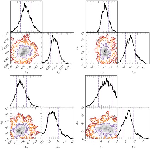
Corner plots from the MCMC of the amplitudes of the modulations within the model. The purple, orange, and red lines show the 1σ, 2σ, 3σ credible intervals, respectively. In all cases, the (0,0) lies outside of the 3σ contour showing that all four parameters are consistent with being modulated.
For the majority of the parameters, the posterior is mostly symmetric and approximately Gaussian. However, this is not true for some of radially emissivity parameters q1, q2, rin, rbr, 1, and rbr, 2 likely due to their interdependence (see equation 15). For completeness they are shown as a corner plot in Fig. D3; all parameters whose posterior distributions are not otherwise shown in this paper are included as histograms in Fig. D4 with symbols matching those in Table 2.
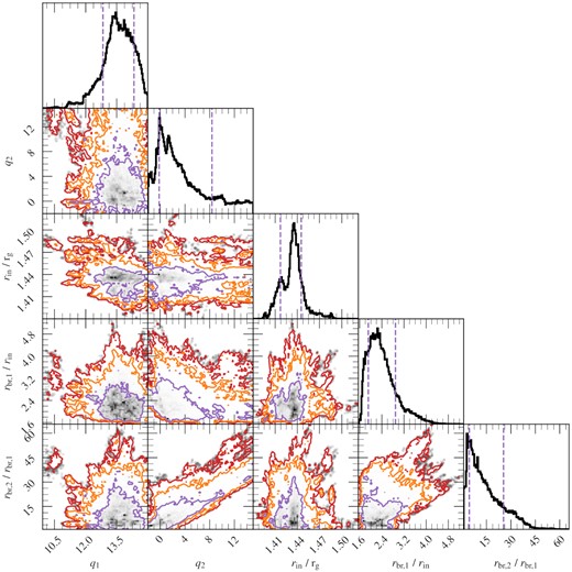
Corner plots from the MCMC of the radial emissivity parameters. The purple, orange, and red lines show the 1σ, 2σ, 3σ credible intervals, respectively. It is important to note that the two break radii rbr,1 and rbr,2 have units of the disc truncation radius rin and rbr,1, respectively. As q1 and q2 are the power-law indices within there relevant break radii, the model becomes insensitive to them when rbr,1 and rbr,2 approach 1, respectively.
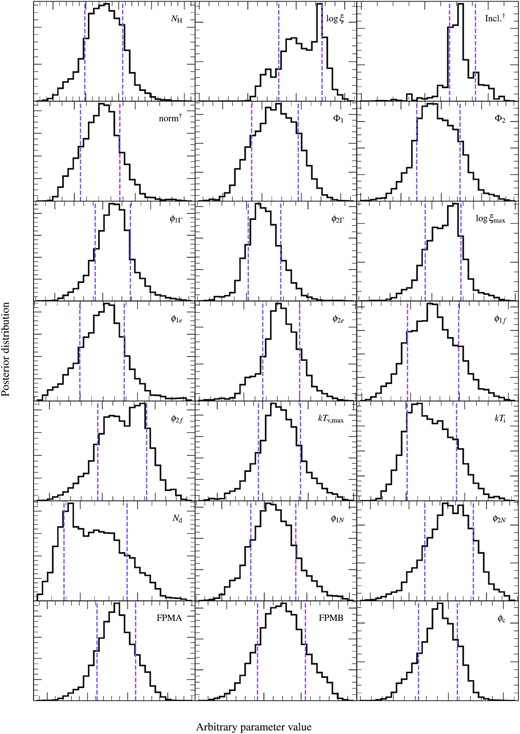
The posteriors of all the parameters not otherwise shown in this paper, with the ±1σ credible interval shown by the dashed purple vertical lines. For visual simplicity, the parameter values are not shown here, as the shape of the distribution is the key feature. The parameters marked with † relate solely to the distant reflector component of the model.
