


ABSTRACT
We present Low-Frequency Array (LOFAR) 143.5-MHz radio observations of flaring activity during 2019 May from the X-ray binary Cygnus X-3. Similar to radio observations of previous outbursts from Cygnus X-3, we find that this source was significantly variable at low frequencies, reaching a maximum flux density of about 5.8 Jy. We compare our LOFAR light curve with contemporaneous observations taken at 1.25 and 2.3 GHz with the RATAN-600 telescope, and at 15 GHz with the Arcminute Microkelvin Imager (AMI) Large Array. The initial 143.5-MHz flux density level, ∼2 Jy, is suggested to be the delayed and possibly blended emission from at least some of the flaring activity that had been detected at higher frequencies before our LOFAR observations had begun. There is also evidence of a delay of more than 4 d between a bright flare that initially peaked on May 6 at 2.3 and 15 GHz, and the corresponding peak (≳ 5.8 Jy) at 143.5 MHz. From the multifrequency light curves, we estimate the minimum energy and magnetic field required to produce this flare to be roughly 1044 erg and 40 mG, respectively, corresponding to a minimum mean power of ∼1038 erg s−1. Additionally, we show that the broadband radio spectrum evolved over the course of our observing campaign; in particular, the two-point spectral index between 143.5 MHz and 1.25 GHz transitioned from being optically thick to optically thin as the flare simultaneously brightened at 143.5 MHz and faded at GHz frequencies.
1 INTRODUCTION
Cygnus X-3 (Giacconi et al. 1967) is a Galactic high-mass X-ray binary, consisting of a Wolf–Rayet star (van Kerkwijk et al. 1992, 1996; Fender, Hanson & Pooley 1999; Koch-Miramond et al. 2002) in orbit with a black hole or neutron star primary compact object. The nature of the primary has been the subject of significant analysis (e.g. Hanson, Still & Fender 2000; Stark & Saia 2003; Hjalmarsdotter et al. 2008; Szostek, Zdziarski & McCollough 2008; Vilhu et al. 2009; Shrader, Titarchuk & Shaposhnikov 2010; Zdziarski, Mikołajewska & Belczyński 2013; Koljonen & Maccarone 2017). Cygnus X-3 is located at Galactic coordinates (l, b) = (79|${_{.}^{\circ}}$|8, +0|${_{.}^{\circ}}$|7), and the distance to the source has been estimated to be ≈ 3.4–10 kpc, with a preferred distance ≈ 7 kpc (e.g. Predehl et al. 2000; Ling, Zhang & Tang 2009; McCollough, Corrales & Dunham 2016).
At radio wavelengths, Cygnus X-3 was first detected by Braes & Miley (1972), who also reported significant variability in their 1.4-GHz observations. Radio flaring from Cygnus X-3 has now been studied for nearly half a century. At frequencies above 1 GHz, the quiescent flux density level is ∼100 mJy (e.g. Waltman et al. 1994; Zdziarski et al. 2018). However, during giant radio outbursts at these frequencies, flux densities of up to ∼20 Jy have been observed (e.g. Gregory & Kronberg 1972; Gregory et al. 1972; Johnston et al. 1986; Waltman et al. 1995; Fender et al. 1997; Tsuboi et al. 2008; Trushkin, Bursov & Nizhelskij 2008a; Corbel et al. 2012; Trushkin et al. 2017a, b; Egron et al. 2017, 2021). During such outbursts, high-resolution radio observations, particularly very-long-baseline-interferometric measurements, have either strongly suggested the presence of relativistic jets in this system, or clearly resolved these structures (e.g. Geldzahler et al. 1983; Spencer et al. 1986; Molnar, Reid & Grindlay 1988; Schalinski et al. 1995; Martí, Paredes & Peracaula 2001; Mioduszewski et al. 2001; Miller-Jones et al. 2004; Tudose et al. 2007). Immediately prior to the periods of bright radio flaring, Cygnus X-3 enters a quenched, ‘hypersoft’ state (e.g. McCollough et al. 1999; Szostek et al. 2008; Koljonen et al. 2010, 2018), where the flux density at GHz frequencies is typically from about one mJy to a few tens of mJy (e.g. Hjellming & Balick 1972; Waltman et al. 1994, 1996; Fender et al. 1997).
Despite there being a number of well-studied radio outbursts from Cygnus X-3, not many low-frequency (<400 MHz) radio observations have been taken during these events. Following the first recorded giant outburst at GHz frequencies in 1972 September (Gregory et al. 1972 et seq.), Bash & Ghigo (1973) conducted 365-MHz monitoring observations with the University of Texas Broadband Synthesis Interferometer. More recently, low-frequency observing campaigns, which also included simultaneous or contemporaneous higher-frequency observations, took place in 2001 September, 2006 May–June, 2007 June, and 2008 April and December (Miller-Jones et al. 2004, 2007; Pal & Rao 2007; Pal, Trushkin & Ishwara-Chandra 2008; Pal, Ishwara-Chandra & Rao 2009; Patra et al. 2015). These low-frequency observations were conducted at 74 and 330 MHz with the Karl G. Jansky Very Large Array (VLA), at 140 MHz with the Westerbork Synthesis Radio Telescope (WSRT), and at 244 and 325 MHz with the Giant Metrewave Radio Telescope (GMRT). Cygnus X-3 is also a variable source at low frequencies, with measured flux densities up to 7.9 Jy (at 365 MHz; Bash & Ghigo 1973), although only 74-MHz upper limits have been reported (Miller-Jones et al. 2004).
During the 1972, 2001, 2006, 2007, and 2008 flaring events, the turnover frequency of the radio spectrum was seen to shift to lower values as each outburst progressed (Marsh, Purton & Feldman 1974 and references therein; Miller-Jones et al. 2004, 2007; Pal et al. 2008, 2009; Trushkin et al. 2008b; Patra et al. 2015). The radio spectral index, α,1 subsequently evolved as well. For example, over a period of 9 d during the 2006 outburst, the two-point spectral index |$\alpha ^{614}_{244}$| changed in value from 1.89 to −0.98, i.e. from being very inverted and optically thick, to steep and optically thin (Pal et al. 2009). The radio spectral evolution of this outburst, as well as the 1972, 2001, 2007, and 2008 events, was discussed in terms of an often-invoked synchrotron bubble model where the emitting plasmons become progressively less optically thick as they propagate outwards and expand (e.g. van der Laan 1966; Hjellming & Johnston 1988; Ball & Vlassis 1993). Mechanisms were also investigated to account for the spectral turnover, namely synchrotron self-absorption, free–free absorption, the Razin–Tsytovich effect, and a low-frequency cutoff in the synchrotron spectrum.
Another study of interest was carried out by Pandey et al. (2007), where 10 simultaneous 235- and 610-MHz GMRT observations of Cygnus X-3 were taken between 2003 July and 2005 January. Although no bright flares were detected, the source was found to be variable at 235 MHz over the time-scale of the observing campaign: the 235-MHz flux density varied between 4.9 and 49 mJy, with a mean of 18 mJy. Inverted radio spectra were reported for all observations, with the two-point spectral index |$\alpha ^{610}_{235}$| per epoch ranging from 0.09 to 1.23.
Observations of outbursting X-ray binaries have been carried out with several facilities from the current generation of low-frequency radio telescopes: the Low-Frequency Array (LOFAR), the Murchison Widefield Array (MWA), and the VLA Low-Band Ionosphere and Transient Experiment (VLITE). In combination with higher-frequency radio observations, these data have allowed valuable constraints to be placed on the broadband spectral properties of the flares. Hence, such observations have offered new insights into the physical processes responsible for the observed emission, as well as the mechanisms responsible for any spectral turnover (e.g. Kassim et al. 2015; Broderick et al. 2015, 2018; Polisensky et al. 2018; Chauhan et al. 2019; also see Marcote et al. 2016 for the case of low-frequency variability from a gamma-ray binary).
In 2019, an ideal opportunity arose to obtain new low-frequency observations of a giant outburst from Cygnus X-3. Monitoring at five separate frequencies between 4.6 and 30 GHz with the RATAN-600 telescope indicated that the radio emission from Cygnus X-3 had become quenched on 2019 February 17 (Trushkin et al. 2019a). Following the quenched phase, radio flaring was observed from 2019 April 17 (observations between 1.25 and 37 GHz with RATAN-600, the Nasu Telescope Array, the Arcminute Microkelvin Imager (AMI) Large Array, and the Metsähovi Radio Observatory), with activity continuing into 2019 May (Koljonen et al. 2019; Tsubono et al. 2019a; Trushkin et al. 2019b; also see Piano et al. 2019a, b for detections of gamma-ray flaring, and Choudhury et al. 2019 for X-ray monitoring).
In this paper, we present LOFAR monitoring observations of Cygnus X-3 during the 2019 April–May event. In Section 2, we describe our LOFAR observations and calibration method. Section 3 discusses imaging, and in Section 4, a LOFAR light curve for Cygnus X-3 is presented, as well as the associated variability statistics. In Section 5, we compare the LOFAR data with contemporaneous radio observations taken at higher frequencies, discussing plausible scenarios for the observed data. We then report our conclusions in Section 6. All uncertainties in this paper are quoted at the 68 per cent confidence level.
2 LOFAR OBSERVATIONS AND DATA REDUCTION
The LOFAR telescope is described in van Haarlem et al. (2013). Our observing campaign (approved target-of-opportunity observations under project code LC11_021; total observing time of 8 h) commenced approximately 15 d after the initial detection of flaring in the radio band. Eight observations were made in total, with an approximately daily cadence for the first six runs, followed by gaps of 3 and 6 d for the final two runs. Observation dates are provided in Table 1.
LOFAR observing log, 143.5-MHz flux densities for Cygnus X-3, root-mean-square (rms) noise levels in the vicinity of Cygnus X-3, multiplicative factors used to correct the flux densities and rms noise levels (Section 3), and details of the synthesized beams. The modified Julian date (MJD) for each run corresponds to the midpoint of the 48-min observation. The quoted internal uncertainties for the flux densities are at the 1σ level, and do not include systematic effects associated with the accuracy of the TGSS flux density scale; see Section 3 and Table 2 for further details. PA is the position angle of the synthesized beam, measured north through east.
| Run | Date | MJD | S143.5 | Noise level | Applied flux density | Angular resolution and PA |
|---|---|---|---|---|---|---|
| (Jy) | (mJy beam−1) | correction factor (×) | (arcsec2; °) | |||
| 1 | 2019 May 2 | 58605.344 | 2.08 ± 0.37 | 51 | 2.33 ± 0.37 | 111 × 88; 80 |
| 2 | 2019 May 3 | 58606.248 | 1.68 ± 0.23 | 62 | 1.76 ± 0.20 | 98 × 92; −54 |
| 3 | 2019 May 4 | 58607.318 | 2.50 ± 0.58 | 64 | 2.27 ± 0.51 | 106 × 90; 89 |
| 4 | 2019 May 5 | 58608.225 | 1.84 ± 0.21 | 58 | 1.44 ± 0.13 | 98 × 92; −45 |
| 5 | 2019 May 6 | 58609.246 | 2.48 ± 0.31 | 88 | 1.84 ± 0.19 | 98 × 92; −58 |
| 6 | 2019 May 7 | 58610.246 | 2.62 ± 0.63 | 128 | 2.28 ± 0.50 | 111 × 99; −47 |
| 7 | 2019 May 10 | 58613.246 | 5.24 ± 0.78 | 154 | 2.03 ± 0.27 | 99 × 91; −63 |
| 8 | 2019 May 16 | 58619.246 | 5.82 ± 0.72 | 131 | 1.80 ± 0.20 | 100 × 91; −72 |
The observations were taken using the high-band antennas (HBA) in the ‘HBA Dual Inner’ configuration. Each observation used 38 LOFAR stations: 24 core stations (each with two sub-stations or ‘ears’) and 14 remote stations. All observations consisted of 48 min on target, preceded or followed by a 10-min scan of a primary calibrator, which was either 3C 295 or 3C 48. Given that Cygnus X-3 can reach flux densities of a Jy or more at low frequencies during an outburst (Section 1), the duration of the target scans was a conservative choice related to expected challenges in imaging each run (as discussed below in this section).
The data were recorded across the frequency range 115–189 MHz, with each of the 380 sub-bands having a bandwidth of 195.3 kHz. However, in this study, we made use of the 240 sub-bands between 120 and 167 MHz (central frequency 143.5 MHz) to reduce issues with radio-frequency interference (RFI), and optimize the bandpass sensitivity. At 143.5 MHz, the primary beam full width at half maximum was 4|${_{.}^{\circ}}$|0 (van Haarlem et al. 2013).
The native temporal and frequency resolutions were 1 s and 64 channels per sub-band, respectively. After preprocessing, including the removal of RFI with aoflagger (Offringa et al. 2010; Offringa, van de Gronde & Roerdink 2012; Offringa, de Bruyn & Zaroubi 2012), as well as dysco compression (Offringa 2016), our data had temporal and frequency resolutions of 4 s and four channels per sub-band, respectively. We then calibrated the data using prefactor (van Weeren et al. 2016; Williams et al. 2016; de Gasperin et al. 2019).2 We used calibrator source models from Scaife & Heald (2012), while the target field sky model used for phase-only calibration was based on data from the 147.5-MHz TIFR GMRT Sky Survey First Alternative Data Release (TGSS ADR1; angular resolution 25 arcsec; Intema et al. 2017). Moreover, the TGSS model included all sources with flux density S147.5 > 300 mJy within 5° of Cygnus X-3.
Imaging Cygnus X-3 with LOFAR is challenging due to (i) the field containing a variety of complex extended emission (e.g. Miller-Jones et al. 2007), and (ii) the very bright source, Cygnus A, is only 6|${_{.}^{\circ}}$|2 away (150-MHz flux density 10.7 kJy; McKean et al. 2016). During preprocessing, an attempt to use the ‘demixing’ algorithm (van der Tol, Jeffs & van der Veen 2007) with standard settings to remove the response from Cygnus A resulted in final processed images that contained no sources. A full direction-dependent calibration would have best ameliorated the problem, and would also have been an excellent test case for LOFAR fields in close proximity to very bright sources. However, this had the potential to become a very time-consuming process. Because we had the additional important consideration of rapidly reporting initial results and ongoing observations to the community (Broderick et al. 2019), we chose instead to process and analyse data sets where Cygnus A had not been removed from the visibilities, and it is these results that we present in this paper. We therefore added a model of Cygnus A from the prefactor software, comprising 12 Gaussian or point-like components, to our target field sky model. Not fully solving for Cygnus A resulted in significant sensitivity and angular resolution penalties, and extra care was also needed to quantify the accuracy of the flux density scale (Section 3 and Appendix A). Nonetheless, we will demonstrate in Section 4 that we were still able to reliably determine the flux densities of Cygnus X-3 and detect statistically significant variability.
3 IMAGING
We used wsclean (Offringa et al. 2014)3 to image our data; an example image is shown in Fig. 1. A projected baseline range of 100–1500λ was implemented; the lower cutoff reduced the contribution from large-scale, diffuse Galactic emission in the field, while the upper cutoff ensured that the angular resolution remained relatively coarse, helping to reduce dynamic range issues associated with Cygnus A. We also used multifrequency deconvolution, grouping the data into six channels of 40 sub-bands each (bandwidth 7.8 MHz per channel). A Briggs robust weighting parameter of −0.5 was selected for all runs except Run 6. In the case of Run 6, we found that we needed to use a lower robust parameter (−1.25) to achieve an angular resolution similar to the other runs. This was likely related to a difference in the weights of the visibilities in the measurement sets for this run, prior to any imaging taking place. It was not entirely clear why the weights were different in this case, but we believe that an appropriate flux density scale correction (as discussed below in this section and in Appendix A) allowed us to measure a reliable flux density for Run 6.
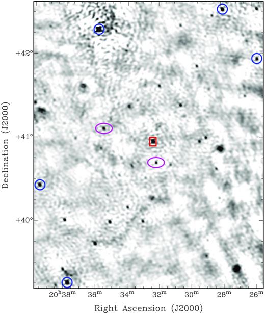
The inner part of our 143.5-MHz map from the first observation on 2019 May 2. Cygnus X-3 is marked with the rectangle, sources used to bootstrap the flux density scale from TGSS (Appendix A) are indicated with circles, and the ellipses mark the two sources whose light curves we show in Fig. A1. Cygnus A is 6|${_{.}^{\circ}}$|2 to the west of the centre of the map (not visible in this zoomed-in view). This image has a synthesized beam of 111 × 88 arcsec2 (PA 80°), and an rms noise level of 51 mJy beam−1 near Cygnus X-3. There is an offset between our astrometry and that of TGSS, such that the LOFAR positions are approximately 30 arcsec to the west-north-west, on average. However, as this offset, as well as similar offsets in the images for the other runs, did not affect any of the analysis presented in this study, no astrometric corrections were applied to the LOFAR data.
The angular resolutions for each of the runs are given in Table 1. The average resolution was about 100 arcsec. Flux density changes resulting from the differing angular resolutions in each of the runs were insignificant compared to the fitting and calibration uncertainties. Henceforth, all results presented are at the native angular resolution of each data set.
Generally speaking, LOFAR flux density calibration requires a bootstrapping step to correct the flux density scale (e.g. Hardcastle et al. 2016). For our data, we used TGSS for bootstrapping. The procedure is described in Appendix A, and the correction factors are given in Table 1. After this step, we then used pybdsf (Mohan & Rafferty 2015) to measure the flux density of Cygnus X-3 in each LOFAR map. The corrected flux densities are given in Table 1. Each flux density uncertainty was determined by combining, using appropriate error propagation, the uncertainty in the correction factor and the flux density fitting uncertainty from pybdsf. As we discuss in Appendix B, despite the relatively coarse angular resolution, possible blending from nearby extended emission was negligible.
The corrected rms noise levels in the vicinity of Cygnus X-3 ranged from 51 to 154 mJy beam−1 (Table 1). Such noise levels are, at best, over an order of magnitude higher than the expected classical confusion limits at the angular resolutions and central frequency of our observations (e.g. Franzen et al. 2016, 2019, and references therein). Given the challenge of calibrating and imaging our observations, we did not attempt to self-calibrate the data using source models derived from the LOFAR maps.
A potential advantage of our wide-bandwidth, low-frequency radio data was to obtain information on the radio spectrum of Cygnus X-3 across the LOFAR high band. However, inspection of the 7.8-MHz bandwidth images produced by wsclean as part of the multifrequency deconvolution process for each run indicated that there were systematic effects across the bandpass, such that all sources in the field of view appeared to have inverted in-band spectra. While we effectively corrected for this on average with our bootstrapping procedure, further corrections across the band were hampered by a paucity of nearby, sufficiently bright sources with literature flux densities at frequencies both below and above the LOFAR high band.
We conservatively assumed that the TGSS flux density scale accuracy is 20 per cent for our target field; see the discussion in Appendix A. In Section 4, we analyse the Cygnus X-3 LOFAR flux densities, which were all bootstrapped to the TGSS flux density scale in the same way, and therefore an additional systematic calibration uncertainty will not affect the main conclusions. In Section 5, however, we include the uncertainty in the low-frequency absolute flux density scale in our multifrequency analysis.
4 CYGNUS X-3 LIGHT CURVE
Our 143.5-MHz light curve for Cygnus X-3 is shown in Fig. 2. The source was bright and significantly detected in all eight observations, well above the quiescent flux density level at this frequency. Indeed, we inspected the 147.5-MHz TGSS image products and calculated a 3σ upper limit for the quiescent flux density of about 30 mJy beam−1. Furthermore, the 235- and 610-MHz results from Pandey et al. (2007) suggest that the average quiescent baseline at 143.5 MHz is well below this TGSS upper limit (see Section 1), as do recently published 325- and 610-MHz GMRT flux densities (Benaglia et al. 2020a,b, 2021).
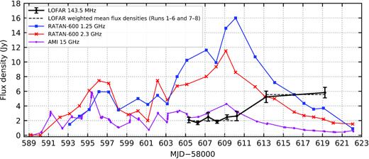
Our LOFAR light curve for Cygnus X-3, using the data from Table 1. The two dashed lines are the inverse-variance-weighted mean flux densities for Runs 1–6 and Runs 7–8, respectively. We have also plotted 1.25-, 2.3-, and 15-GHz light curves from the contemporaneous RATAN-600 and AMI monitoring programmes (Section 5.1). The error bars for the LOFAR data points are ±1σ. For the purposes of clarity, we have not plotted the uncertainties for the RATAN-600 and AMI flux densities; the uncertainties are 100–300 mJy at 1.25 GHz, and 5 per cent at both 2.3 and 15 GHz. The 2.3-GHz data point for MJD − 58000 = 590.171 is an upper limit (<20 mJy). The assumed 20 per cent uncertainty in the absolute flux density scale of both TGSS and our bootstrapped LOFAR data (Section 3 and Appendix A), not accounted for in the plotted error bars, could result in a systematic shift of the LOFAR light curve.
Within the uncertainties, Cygnus X-3 had an approximately constant flux density from May 2 to 7 (MJD 58605–58610), but then brightened between May 7 and 10 (MJD 58610 and 58613). The inverse-variance-weighted mean flux densities of Runs 1–6 and 7–8 were 1.98 ± 0.12 and 5.55 ± 0.53 Jy, respectively, where each uncertainty is the standard error of the weighted mean (Fig. 2). Therefore, the average flux density increased by a factor of 2.8 ± 0.3 between these two observational subsets. The latter mean flux density was also over a factor of two brighter than the peak 140-MHz flux density of 2.3 Jy during the 2006 May outburst (Miller-Jones et al. 2007; also see Section 1).
5 PROPERTIES OF THE 2019 MAY BRIGHT FLARE
5.1 Comparison with contemporaneous, higher-frequency data
We compared our LOFAR light curve with contemporaneous, independent observing campaigns carried out at higher frequencies. In particular, in Fig. 2, we show the 1.25- and 2.3-GHz light curves from RATAN-600, as well as a 15-GHz light curve from the AMI Large Array. Overviews of these facilities can be found in Khaikin et al. (1972; RATAN-600), as well as Zwart et al. (2008; AMI) and Hickish et al. (2018; AMI).
From the commencement of flaring, until a few days after the end of our LOFAR observations, there were 23 RATAN-600 observations taken at 1.25 GHz and 29 at 2.3 GHz. An initial description of the data can be found in Trushkin et al. (2019b). Mostly a daily observing cadence was used. The 1.25-GHz observations had a beam size of approximately 12.9 × 2.2 arcmin2, while the beam size at 2.3 GHz was approximately 7.0 × 1.2 arcmin2 (PA 0° in both cases; see Majorova & Trushkin 2002 for further details of the RATAN-600 beam patterns). NGC 7027 was used as the primary flux density calibrator, and the flux density uncertainty per target measurement was 100–300 mJy (1.25 GHz) or 5 per cent (2.3 GHz). The full set of monitoring data, spanning seven separate frequencies from 1.25 to 30 GHz, will be presented in a future paper.
A total of 212 AMI monitoring scans are also shown in Fig. 2. Typically, 5 × 10-min scans were taken per day, interleaved with short scans of the phase calibrator, J2052+3635. The observations had an angular resolution of approximately 30 arcsec. Note that the telescope measures Stokes I + Q (i.e. a single linear polarization). The primary calibrator was 3C 286, and additional small flux density corrections were made using J2052+3635. We have conservatively assumed an uncertainty of 5 per cent for each Cygnus X-3 flux density measurement. The full set of AMI monitoring data will also be presented in a future paper.
In Fig. 2, we can see that there was bright and prolonged flaring from Cygnus X-3 at GHz frequencies during 2019 April–May, with multiple flare peaks at each frequency. As previously mentioned in Section 4, the LOFAR flux density initially remained relatively stable, albeit at a heightened brightness compared to the normal quiescent level. This behaviour was very likely due to the associated delay expected between individual flares at high and low frequencies (see Section 1 and references therein, as well as further discussion in Section 5.4). It is also evident that while the higher-frequency light curves peaked on MJDs 58609 and 58610 and then started to decay, the LOFAR light curve clearly exhibited a delayed flux density rise only after MJD 58610. We consider it unlikely that the 143.5-MHz peak was at or very near the time of Run 7 (MJD 58613), as the subsequent flare decay would have been almost flat initially, and markedly different to what was observed at GHz frequencies. However, due to the 6-d gap between our final two observations (MJD 58613–58619), it is unclear whether the flare peaked between Runs 7 and 8, during Run 8, or after our last observation.
5.2 Broadband spectral characteristics
We explored the spectral characteristics of the light curves (Table 2). The RATAN-600 and AMI flux densities were linearly interpolated to the MJDs of the LOFAR data using the two nearest measurements in time. Relative to the closest measurement in time in each case, these adjustments were at most 21 per cent, with a median of 2.0 per cent and only two instances above 5.9 per cent. Because our analysis would not be significantly improved by accounting for the uncertainties associated with these mostly small corrections, for simplicity we assumed that the interpolated RATAN-600 and AMI flux densities had the same absolute or relative uncertainties as described in Section 5.1. Furthermore, as we were directly comparing the LOFAR flux densities with GHz-frequency measurements, we added the aforementioned 20 per cent absolute flux scale uncertainty from the TGSS bootstrapping process (Section 3) in quadrature with the previously reported uncertainty for each LOFAR flux density as given in Table 1.
Flux densities, two-point spectral indices, and fitted spectral indices for each LOFAR run. As we were directly comparing the LOFAR flux densities with higher-frequency data points, we added the 20 per cent flux density scale uncertainty at 143.5 MHz in quadrature with the calibration and fitting uncertainties described in Section 3 and reported in Table 1. The flux densities at GHz frequencies were linearly interpolated to the MJDs of our LOFAR observations. Further details can be found in Section 5.2.
| Run | MJD | S143.5 | S1250 | S2300 | S15000 | |$\alpha ^{1250}_{143.5}$| | |$\alpha ^{2300}_{1250}$| | |$\alpha ^{15000}_{2300}$| | αfitted and |$\chi ^2_{\rm red}$| |
|---|---|---|---|---|---|---|---|---|---|
| (Jy) | (Jy) | (Jy) | (Jy) | (1250–15 000 MHz) | |||||
| 1 | 58605.344 | 2.1 ± 0.6 | 10.4 ± 0.2 | 7.1 ± 0.4 | 2.45 ± 0.12 | 0.74 ± 0.13 | −0.63 ± 0.10 | −0.57 ± 0.04 | −0.58 ± 0.02; 0.21 |
| 2 | 58606.248 | 1.7 ± 0.4 | 11.0 ± 0.2 | 7.5 ± 0.4 | 2.49 ± 0.12 | 0.86 ± 0.11 | −0.63 ± 0.09 | −0.59 ± 0.04 | −0.60 ± 0.02; 0.11 |
| 3 | 58607.318 | 2.5 ± 0.8 | 11.3 ± 0.2 | 8.3 ± 0.4 | 3.17 ± 0.16 | 0.70 ± 0.15 | −0.51 ± 0.08 | −0.51 ± 0.04 | −0.51 ± 0.02; 0.0042 |
| 4 | 58608.225 | 1.8 ± 0.4 | 10.4 ± 0.2 | 9.6 ± 0.5 | 3.68 ± 0.18 | 0.81 ± 0.10 | −0.13 ± 0.09 | −0.51 ± 0.04 | −0.41 ± 0.02; 8.7 |
| 5 | 58609.246 | 2.5 ± 0.6 | 14.8 ± 0.3 | 11.1 ± 0.6 | 4.22 ± 0.21 | 0.82 ± 0.11 | −0.47 ± 0.09 | −0.52 ± 0.04 | −0.50 ± 0.02; 0.12 |
| 6 | 58610.246 | 2.6 ± 0.8 | 15.7 ± 0.3 | 8.5 ± 0.4 | 3.16 ± 0.16 | 0.83 ± 0.14 | −1.01 ± 0.08 | −0.53 ± 0.04 | −0.66 ± 0.02; 22 |
| 7 | 58613.246 | 5.2 ± 1.3 | 8.7 ± 0.3 | 5.2 ± 0.3 | 1.55 ± 0.08 | 0.24 ± 0.12 | −0.84 ± 0.11 | −0.65 ± 0.04 | −0.69 ± 0.03; 2.1 |
| 8 | 58619.246 | 5.8 ± 1.4 | 3.6 ± 0.2 | 2.1 ± 0.1 | 0.50 ± 0.03 | −0.22 ± 0.11 | −0.88 ± 0.12 | −0.77 ± 0.04 | −0.79 ± 0.03; 0.70 |
The two-point and fitted radio spectra in Table 2 varied significantly over the course of our observing campaign, both in terms of brightness and spectral slope/shape. We show this further in Fig. 3, where we have plotted broadband radio spectra at MJDs corresponding to Runs 1, 5, 6, 7, and 8. Initially, above 1.25 GHz, the spectrum was well described by a single power law with a rather canonical spectral index of −0.58 ± 0.02. Below 1.25 GHz, the spectrum turned over and the two-point spectral index |$\alpha ^{1250}_{143.5}$| was optically thick (0.74 ± 0.13). By the end of our observations, the broadband spectrum had clearly evolved: the LOFAR data point was the brightest of the four flux density measurements, and the spectrum did not turn over in the same pronounced way that the previous epochs showed. Indeed, |$\alpha ^{1250}_{143.5}$| was now flat and optically thin (−0.22 ± 0.11), and above 1.25 GHz the spectral index had steepened to −0.79 ± 0.03. A simple explanation for this overall spectral variation could be as postulated in other studies (Section 1): as the synchrotron-emitting plasmons from the outburst expanded as they travelled away from the Cygnus X-3 system, they became progressively less optically thick at lower frequencies, and subsequently the spectral turnover frequency shifted to lower values as the flare simultaneously decayed at the higher frequencies. However, as we will discuss further in Section 5.4, then we would have expected the flare to be brightest at our highest observing frequency of 15 GHz (e.g. van der Laan 1966).
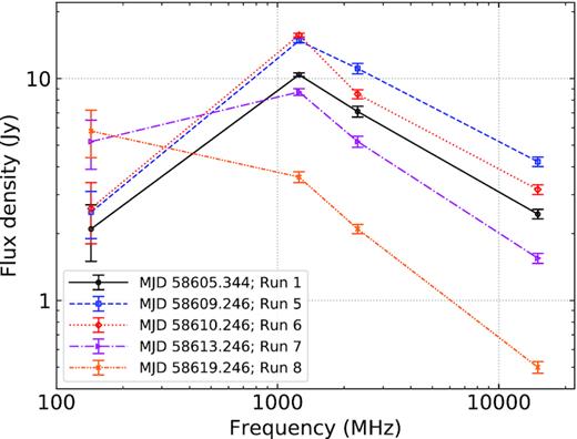
Radio spectra for five selected runs: 1, 5, 6, 7, and 8. We have used the data presented in Table 2; see the table caption for further details. Plotted lines are not fits to the data, but rather illustrate how the two-point spectral index changed as a function of frequency at a particular epoch. Run 1 shows the initial shape of the radio spectrum when our LOFAR observing campaign commenced, Runs 5 and 6 were very close to the peak of the flaring as measured at the higher frequencies, and Runs 7 and 8 are of particular interest because of the significant increase in the LOFAR flux density. The broadband radio spectrum clearly evolved over the course of the flare.
At GHz frequencies, both Table 2 and Fig. 3 show that, in general, single-power-law spectral fits are appropriate for most of the epochs. Discrepancies are most apparent for Runs 4 and 6, however: there is either strong or very strong statistical evidence that our model in equation (3) does not appropriately describe the data for these two cases (P-values of 3 × 10⁻³ and 3 × 10⁻⁶ that |$\chi ^2_{\rm red}$| would be larger for Runs 4 and 6, respectively). For Run 4, it is interesting to note that there was a 1-d dip in the 1.25-GHz flux density a few days before the flare peaked at this frequency. For Run 6, the flare was peaking at 1.25 GHz, yet had begun to decay at 2.3 and 15 GHz. Therefore, the standard delay in the evolution of the flare with decreasing frequency would very likely explain any deviation from a single power law at the epoch of Run 6. This delay would also explain why |$\alpha ^{2300}_{1250}$|, |$\alpha ^{15000}_{2300}$| and the 1.25–15 GHz fitted spectral index either clearly follow, or show hints of, a general trend of first flattening as the flare peaked at higher frequencies, and then steepening thereafter. The broadband GHz-frequency spectrum was also still steepening at the end of our observing campaign, with the spectral index having not reached a possible terminal value, as seen in some previous studies (e.g. discussion in Miller-Jones et al. 2004, and references therein). On the contrary, 3 d after our LOFAR observations ended, the spectrum between 1.25 and 15 GHz had evolved significantly, with evidence of turnover owing to rapid decay at 1.25 GHz (Fig. 2). Further analysis of the GHz-frequency data will be presented in future papers.
An approximately constant value of |$\alpha ^{1250}_{143.5} \approx 0.8$| was observed from Runs 1–6. The subsequent evolution of this two-point spectral index between Runs 1–6 and 8, |$\Delta \alpha ^{1250}_{143.5} \approx -1$|, was much more pronounced than the moderate net steepening that occurred at the higher frequencies over the course of the observing campaign (Δαfitted ≈ −0.2). It is interesting to note that while there was a significant steepening in |$\alpha ^{1250}_{143.5}$| for Run 6 due to the flare peaking at 1.25 GHz and beginning to decay at 2.3 GHz, |$\alpha ^{1250}_{143.5}$| remained at a similar value as determined for the previous runs; we may have expected |$\alpha ^{1250}_{143.5}$| to become more inverted at this epoch due to the further delay in the flare peaking below 1.25 GHz. However, it is likely that the comparison of the |$\alpha ^{1250}_{143.5}$| values for Runs 1–6 is affected by the relative lack of precision in the LOFAR flux density measurements.
5.3 Modelling the spectral turnover
We fitted the models shown in equations (4–7) to the data presented in Table 2. Generally speaking, synchrotron self-absorption and free–free absorption (both scenarios for the latter) were plausible absorption mechanisms for all runs apart from Runs 4 and 6, where, as described above, the optically thin GHz-frequency spectrum was not well fitted by a single power law. The Razin–Tsytovich fit results were generally poor, aside from Run 8. In Fig. 4 we show the model fits for Runs 1 and 8, and in Table 3 we give the fitted parameter values for these two runs. Table C1 in Appendix C contains the fitting results for all eight runs. Similar to the fitting described in Section 5.2, the |$\chi ^2_{\rm red}$| values in Tables 3 and C1 suggest that the flux densities have overestimated uncertainties. However, given that there were only two degrees of freedom for each model fitted, the formal standard deviation for the |$\chi ^2_{\rm red}$| distribution is again relatively large, and equal to unity. Furthermore, we caveat that our results would be strongly affected by blending of individual flares caused by the prolonged activity, particularly at LOFAR frequencies (additional discussion in Section 5.4).
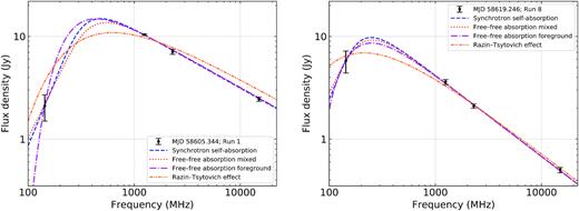
Broadband radio spectra from Runs 1 and 8 (left-hand and right-hand panels, respectively), overlaid with the model fits described in equations (4–7). The fitted parameters are given in Table 3. Aside from the Razin–Tsytovich effect for the first epoch (shown in the left-hand panel as the dot-dot-dashed line, which has |$\chi ^2_{\rm red} = 21$|) all models are plausible for both runs. This result emphasizes the need for observational constraints between 143.5 and 1250 MHz, in particular below ∼800 MHz, to better constrain the frequency and flux density of the spectral turnover, and in turn its likeliest cause. See Section 5.3 for further details.
Turnover frequencies, fitted model parameters, and goodness-of-fit statistics for the models described in Section 5.3. A subset of the fits (for Runs 1 and 8) is plotted in Fig. 4. Results for all of the runs can be found in Table C1 in Appendix C. The fit types given below are abbreviated descriptions of mechanisms (i–iv) described in equations (4–7).
| Run and | νp | ντ | Sτ | |$\chi ^2_{\rm red}$| |
|---|---|---|---|---|
| type of fit | or νRT | or SRT | ||
| (MHz) | (MHz) | (Jy) | ||
| 1; SSA | 490 | 360 ± 30 | 13.6 ± 0.7 | 0.23 |
| 1; FFA mixed | 550 | 410 ± 40 | 12.7 ± 0.7 | 0.47 |
| 1; FFA foreground | 440 | 240 ± 10 | 10.3 ± 0.3 | 0.53 |
| 1; RT effect | 630 | 360 ± 20 | 9.8 ± 0.3 | 21 |
| 8; SSA | 250 | 200 ± 20 | 9.3 ± 0.7 | 0.37 |
| 8; FFA mixed | 260 | 210 ± 20 | 8.9 ± 0.7 | 0.38 |
| 8; FFA foreground | 250 | 160 ± 20 | 6.7 ± 0.5 | 0.44 |
| 8; RT effect | 210 | 170 ± 30 | 6.8 ± 0.9 | 1.8 |
Consistent with our previous discussion (Section 5.2), regardless of mechanism, νp shifted to a lower value over the course of our observations (Tables 3 and C1). Filling in the frequency gap between the LOFAR and RATAN-600 data, for example at 325 and 610 MHz with the upgraded GMRT (uGMRT), would have provided better constraints on the turnover frequency at each epoch, potentially allowing us to identify the most probable absorption mechanism(s). In the following section, we continue the discussion of this topic, but this time examining the peak flux density of the flare as a function of frequency.
5.4 Comparing the 143.5-MHz flare peak with model predictions
We also investigated whether the 143.5-MHz flare was brighter or fainter than expected given the higher-frequency properties (Fig. 5). First, we made the assumption that the expected quiescent baseline at each frequency (see Sections 1 and 4) was negligible in comparison to the much brighter peak flux density. Similarly to the analysis in Section 5.2, we then fitted a single power law to the radio spectrum of GHz-frequency peak flux densities from Fig. 2 (16.0 ± 0.3, 11.50 ± 0.58, and 4.28 ± 0.21 Jy at 1.25, 2.3, and 15 GHz, respectively), which yielded a spectral index of −0.53 ± 0.02 (|$\chi ^2_{\rm red}=0.015$|). Therefore, this spectrum was also optically thin to at least as low as 1.25 GHz.
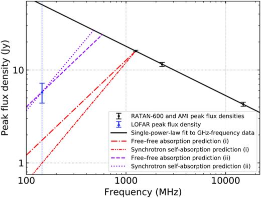
Peak flux densities of the flaring activity in 2019 May as a function of frequency. The LOFAR peak flux density (Run 8 in Table 2) is shown with a triangle to indicate that it is effectively a lower limit given our limited sampling. The black line is the (extrapolated) single-power-law fit to the GHz-frequency flux densities (Section 5.4). As described in Section 5.4, we also show predictions from the Martí, Paredes & Estalella (1992) model for both the free–free absorption and synchrotron self-absorption cases: (i) the spectrum turns over immediately below 1.25 GHz, and (ii) the spectrum turns over at lower frequencies such that the predictions match our measured LOFAR peak flux density. The vertical blue line has been plotted to help indicate the predicted 143.5-MHz flux densities for (i). In practice, the spectral turnover would be smoother than indicated in this figure.
Martí et al. (1992) developed a model for describing outbursts from Cygnus X-3, featuring twin jets that (i) are laterally expanding, and (ii) into which relativistic electrons are being injected. They found that it could describe the properties of the 1972 September outburst over the frequency range 0.4–90 GHz (i.e. slightly above our LOFAR observing frequency at the lower end of this range). This was in contrast to invoking the often-used van der Laan (1966) model. The peak flux densities of Cygnus X-3 from the 2019 May flare were also not consistent with the van der Laan (1966) synchrotron bubble model, given that (i) the peak flux density decreased with increasing frequency above 1 GHz, and (ii) the LOFAR peak flux density was significantly brighter than would have been predicted (see e.g. similar results from LOFAR monitoring of the X-ray binary SS 433; Broderick et al. 2018). Also note that, for example, the continued production of relativistic electrons was hypothesized to explain the increase in flux density with decreasing frequency in the 1991 January 31 outburst from the black hole X-ray binary GRS 1124 − 68 / Nova Muscae 1991 (Ball et al. 1995).
There are at least two possible scenarios to explain the discrepancy. First, the turnover frequency in the radio spectrum of peak flux densities may have been significantly below 1.25 GHz. Using equations (9 and 10), to ensure consistency with our brightest 143.5-MHz flux density of 5.8 Jy, the radio spectrum would have needed to transition from the optically thin to optically thick regime at frequencies of roughly 580 and 470 MHz for the cases of free–free absorption and synchrotron self-absorption, respectively. The mid-frequency peak flux densities would have then potentially reached values >20 Jy, not seen before in previous flaring events. For comparison, the maximum 614-MHz flux density in the Pal et al. (2009) study of the 2006 outburst was about 7.5 Jy. Additionally, Anderson et al. (1972) measured a maximum 408-MHz flux density of over 7 Jy in 1972 September; also see the 408-MHz monitoring results from Bonsignori-Facondi & Montebugnoli (1989), which covered the period 1983 November – 1985 September, and in which the highest flux density was 2.2 Jy. In practice, the transition from the optically thin to optically thick regime would have been smoother than indicated in Fig. 5, both reducing the highest peak flux density at mid frequencies and shifting the transition frequency to a higher value. Nonetheless, the data in Fig. 5 (as well as the fitting results in Tables 3 and C1) strongly suggest that this flare was very bright at mid frequencies.
Secondly, the underlying physics may require a different modelling approach, particularly as the overall flaring activity was extended over a period of more than 1 month. In fact, this more than likely complicates the analysis, as the emission from an ensemble of discrete flares would have become blended together, particularly at low frequencies where the rise times are, generally speaking, significantly longer. If we assume that the effective baseline level at 143.5 MHz was roughly 2 Jy before the final bright flare (i.e. this was the remaining low-frequency response from the flaring prior to our observations taking place), then the effective 143.5-MHz peak flux density was ≳ 3.8 Jy. This could help to reconcile the LOFAR peak flux density with the predictions of the Martí et al. (1992) model, although a thorough comparison would also involve determining appropriate baseline levels from the previous flaring activity at the higher frequencies too. As an estimate, not including baseline corrections at higher frequencies, the transition from the optically thin to optically thick regime would be shifted upwards to frequencies of roughly 760 and 600 MHz for the cases of free–free absorption and synchrotron self-absorption, respectively. Furthermore, although beyond the scope of this paper, an alternative approach could be to use a model such as the one presented in Lindfors et al. (2007), which assumes that an outburst can be explained by internal shocks in the jets, and decomposes the activity into a separate number of flaring events.
We can also see in Fig. 2 that the flare peaked about 1 d later at 1.25 GHz (MJD 58610) than it did at 2.3 and 15 GHz (MJD 58609). The daily, or sometimes longer sampling cadence at all three frequencies meant that it was not possible to further quantify the delay as a function of frequency at and above 1.25 GHz. It was also difficult to assess with confidence the delay between 2.3/15 GHz and 143.5 MHz. However, for example, if the 143.5-MHz flare had peaked at or near the time of our final LOFAR observation, then the delay would have been approximately 10 d. This is not unreasonable, given both the results of previous low-frequency studies (Bash & Ghigo 1973; Miller-Jones et al. 2004, 2007; Pal et al. 2009), and the model delays determined by Martí et al. (1992). A very conservative lower limit would be about 4 d, based on the time gap between the 2.3/15-GHz peak and our Run 7 (but see discussion in Section 5.1).
5.5 Flare energetics
We used the analytical framework presented in Fender & Bright (2019), placing estimates on the minimum energy, power, and magnetic field required for the bright May flare. Their analysis is based on the assumption that the evolution of a radio flare is due to changes in the synchrotron self-absorption optical depth. We estimated that the minimum energy was Emin ∼ 1044 erg, corresponding to a minimum power Pmin ∼ 1038 erg s−1 and a magnetic field at Emin of Bmin ∼ 40 mG. We also estimated that the expansion velocity of the flare was ≲ 0.6c, with a size ≲ 6 × 10¹³ m and brightness temperature ≳ 4 × 10¹⁰ K. Due to our low observing frequency, our minimum energy and power estimates are about an order of magnitude higher than values calculated for Cygnus X-3 by Fender & Bright (2019), who reported on 2.3- and 8.3-GHz monitoring of flaring in 1994.4 As a result, our determined Bmin is also lower than that calculated by Fender & Bright (2019).
Using the rise time and maximum brightness of our LOFAR monitoring as an alternative estimate for the jet energetics (e.g. see Fender 2006), we obtained similar values for the above quantities, albeit a factor of a few lower. These values are comparable to estimates using the same method for radio flares from a number of other X-ray binaries (e.g. Fender et al. 1999; Fender 2006; Brocksopp et al. 2007; Curran et al. 2014; Russell et al. 2019).
5.6 A comment on our observing strategy
It could perhaps be regarded as unfortunate that our sampling was at a higher cadence when the 143.5-MHz flux density was approximately constant at the ∼2-Jy level. Initially, when we triggered our LOFAR observing campaign, it was not entirely clear from evidence available at the time if the source would continue to flare. Hence, there was a strong consideration to obtain several monitoring observations as quickly as possible. Also, because of the challenges in calibrating and imaging our data (Sections 2 and 3), there was enough of a latency between observations and initial flux density measurements (over 1 week) such that we could not easily adjust the observing strategy on the fly. The lessons learned in this study will be valuable in optimizing the strategy for future monitoring observations.
6 CONCLUSIONS AND FUTURE WORK
In this study, we presented and analysed LOFAR high-band observations of the 2019 April–May outburst from the X-ray binary Cygnus X-3. Moreover, we compared our LOFAR data with contemporaneous observations taken with the RATAN-600 and AMI telescopes at frequencies of 1.25, 2.3, and 15 GHz. Our conclusions are as follows.
Over a two-week observing period (May 2–16), we detected statistically significant variability from Cygnus X-3. In all eight observations, the source was bright and detected well above the usual quiescent flux density level, with the 143.5-MHz flux density in each observing run ranging from about 1.7 to 5.8 Jy.
An approximately constant initial 143.5-MHz flux density level of ∼2 Jy from May 2–7 was suggested to be the delayed and potentially blended low-frequency emission from at least some of the flaring activity that was detected at GHz frequencies prior to our observing campaign taking place.
The subsequent increase in the 143.5-MHz flux density by nearly a factor of three, to a measured peak of 5.8 Jy on May 16, was interpreted as the low-frequency equivalent of the bright flare seen on May 6/7 at GHz frequencies. There is a tentative suggestion that the peak 143.5-MHz flux density was significantly brighter than would be expected given the properties of the flare at GHz frequencies. While there is evidence that the low-frequency peak was delayed by more than 4 d compared to the peaks at 2.3 and 15 GHz on May 6, our light curve sampling was not sufficiently fine enough to determine with certainty when the 143.5-MHz peak occurred. It is possible that the 143.5-MHz light curve continued to rise after our observations ended, or the flare peaked between Runs 7 and 8 (i.e. between May 10 and 16).
As in other studies of Cygnus X-3 in outburst, we found that there was a clear evolution in the broadband radio spectrum. In particular, the amount of spectral curvature below 1.25 GHz significantly decreased (|$\Delta \alpha ^{1250}_{143.5} \approx -1$|), implying that the turnover frequency had shifted to lower frequencies over the course of our LOFAR observing campaign. A simple interpretation is that the outburst became progressively less optically thick at lower frequencies as it progressed. However, we did not have enough radio spectral coverage to conclusively identify whether synchrotron self-absorption or free–free absorption was responsible for the spectral turnover, nor could we determine a fully satisfactory explanation for how the peak flux density varied as a function of frequency. Further modelling and analysis is needed.
We estimated a number of physical properties of the bright flare for which we had the LOFAR coverage, in particular a minimum energy, magnetic field and mean power of roughly 1044 erg, 40 mG, and 1038 erg s−1, respectively. Our values are broadly consistent with previous outbursts of both Cygnus X-3 and other X-ray binaries.
As discussed in Section 2, successful direction-dependent calibration, as well as the subsequent subtraction of Cygnus A from the visibilities, would allow higher-resolution, higher-dynamic-range maps to be constructed. These refined images could then be used to investigate in further detail how much Cygnus X-3 varied from run to run over the course of our observing campaign. The in-band spectral properties could potentially be better analysed too.
In the case of the 2019 April–May flaring from Cygnus X-3, additional activity was detected shortly afterwards in 2019 June (Tsubono et al. 2019b; Piano et al. 2019c), including an even brighter radio outburst (S. Trushkin, priv. comm.). Further outbursts were detected in 2020 February and June (Egron et al. 2020; Green & Elwood 2020; Piano et al. 2020; Trushkin et al. 2020a, b; Tsubono et al. 2020a,b). For the next giant outburst from Cygnus X-3, it would be valuable to have high-cadence, low-frequency monitoring over the full duration of the flaring. If Cygnus X-3 were to reach Jy-level flux densities again in the LOFAR high band during such an outburst, then reducing each monitoring scan in length by a factor of two would still give sufficient (u, v) coverage for imaging (e.g. the strategy used for LOFAR monitoring of the microquasar SS 433 by Broderick et al. 2018). Additional observations in the LOFAR low band (30–80 MHz) could also be of interest, particularly to better constrain spectral turnover, and to search for a cut-off frequency in the synchrotron spectrum.
ACKNOWLEDGEMENTS
We are saddened to report that Dr G. G. Pooley passed away before this paper was published. For many decades, Dr Pooley made considerable contributions to a variety of projects, including the monitoring of Cygnus X-3 and many other variable radio sources using the Cambridge 5-km and Ryle telescopes, and most recently the AMI telescope.
We thank the referee for their helpful comments and suggestions, which improved the presentation of this paper.
This paper is based on data obtained with the International LOFAR Telescope (ILT) under project code LC11_021. LOFAR (van Haarlem et al. 2013) is the Low Frequency Array designed and constructed by ASTRON. It has observing, data processing, and data storage facilities in several countries that are owned by various parties (each with their own funding sources), and that are collectively operated by the ILT foundation under a joint scientific policy. The ILT resources have benefitted from the following recent major funding sources: CNRS-INSU, Observatoire de Paris and Université d’Orléans, France; BMBF, MIWF-NRW, MPG, Germany; Science Foundation Ireland (SFI), Department of Business, Enterprise and Innovation (DBEI), Ireland; NWO, the Netherlands; The Science and Technology Facilities Council, UK; Ministry of Science and Higher Education, Poland.
Observations with the RATAN-600 radio telescope are supported by the Ministry of Science and Higher Education of the Russian Federation. For AMI, we acknowledge support from the European Research Council under grant ERC-2012-StG-307215 LODESTONE. We thank the staff of the Mullard Radio Astronomy Observatory for support in the operation of AMI.
TDR acknowledges support from a Netherlands Organisation for Scientific Research (NWO) Veni Fellowship and a financial contribution from the agreement ASI-INAF n.2017-14-H.0. DRAW and JSB were supported by the Oxford Centre for Astrophysical Surveys, which is funded through generous support from the Hintze Family Charitable Foundation.
We thank the ASTRON Radio Observatory, particularly Sander ter Veen and Pietro Zucca, for promptly setting up and scheduling the observations described in this paper, preprocessing the data, and providing advice on some data reduction issues. We also thank the ASTRON Radio Observatory for kindly granting us processing time on the CEP3 cluster, André Offringa and Sarrvesh Sridhar for helpful feedback on a wsclean imaging question, Huib Intema and Anna Kapińska for useful suggestions regarding the accuracy of the low-frequency flux density scale, and James Miller-Jones for providing us with a 330-MHz WSRT map of the Cygnus X-3 field.
This research has made use of the VizieR catalogue access tool, CDS, Strasbourg, France (DOI: 10.26093/cds/vizier). The original description of the VizieR service was published in A&AS 143, 23 (Ochsenbein, Bauer & Marcout 2000). This research has made use of the SIMBAD database, operated at CDS, Strasbourg, France (Wenger et al. 2000). This research has made use of NASA’s Astrophysics Data System Bibliographic Services. This project also made use of kern (Molenaar & Smirnov 2018), kvis (Gooch 1995), matplotlib (Hunter 2007), numpy (Oliphant 2006), scipy (Virtanen et al. 2020), topcat (Taylor 2005), and Overleaf (http://www.overleaf.com).
DATA AVAILABILITY
The preprocessed LOFAR data sets used in this study are available under project code LC11_021 in the LOFAR Long-Term Archive (https://lta.lofar.eu). Calibrated LOFAR data and images will be shared on reasonable request to the corresponding author. The RATAN-600 and AMI flux density data sets will be presented in future papers; please contact the corresponding author for further information. TGSS data products are available at http://tgssadr.strw.leidenuniv.nl/doku.php.
Footnotes
Sν ∝ να, where Sν is the flux density at frequency v. Moreover, in this paper, we use the notation |$\alpha ^{\nu _2}_{\nu _1}$| to denote a two-point spectral index between ν1 and ν2 MHz.
REFERENCES
APPENDIX A: CORRECTING THE FLUX DENSITY SCALE OF THE LOFAR DATA
To bootstrap the flux density scale from TGSS, we used five well-spaced, bright comparison sources with S147.5 > 1 Jy that are within 2° (i.e. the primary beam half power point) of Cygnus X-3. In order of decreasing brightness, these sources are J203556.7+421747, J203745.3+391533, J202753.4+423158, J203934.1+402539, and J202542.8+415615 (marked in Fig. 1 with circles). Source finding in our LOFAR maps was carried out with pybdsf; we then calculated the TGSS/LOFAR integrated flux density ratio for each of our comparison sources, per run. For a given run, the mean flux density ratio was used as the bootstrapping correction factor, and the associated uncertainty was the standard deviation of the flux density ratios. For Run 6, J202542.8+415615 was removed from the comparison as the signal-to-noise ratio was too low (<5) in the LOFAR map. The correction factors to multiply the LOFAR flux densities by ranged from 1.44 to 2.33, with relative 1σ uncertainties ranging from 9 to 22 per cent (Table 1). No significant evidence was found to suggest that the correction factors were correlated with either the radial distance from the field centre, or the position within the field. We did not correct for the different central frequencies of our data and TGSS (i.e. 143.5 and 147.5 MHz), because this was a second-order effect compared to the scatter in each correction factor. We also did not weight the data when deriving the correction factors: this gave a more conservative estimate of the scatter associated with the bootstrapping. Finally, given the 2-week time-scale of our observing campaign, the derived corrections were very unlikely to have been affected by any variability from the comparison sources (e.g. see results from Bell et al. 2019).
To demonstrate confidence in the bootstrapping procedure, in Fig. A1 we show the corrected 143.5-MHz light curves of two moderately bright TGSS sources that are relatively close to Cygnus X-3 on the sky (marked in Fig. 1 with ellipses). These sources are J203214.1+404223 (0|${_{.}^{\circ}}$|25 from Cygnus X-3; TGSS catalogued flux density S147.5 = 769 ± 79 mJy) and J203533.2+410645 (0|${_{.}^{\circ}}$|61 from Cygnus X-3; S147.5 = 766 ± 78 mJy). As before, pybdsf was used for source finding and flux density measurements in the LOFAR maps. After bootstrapping, these two sources had flat light curves (within the uncertainties) during our observing campaign. Moreover, the inverse-variance-weighted mean 143.5-MHz flux densities, 740 ± 60 and 730 ± 60 mJy, respectively (where each uncertainty is the standard error of the weighted mean), were consistent with the TGSS catalogue values stated above. Note that there was still an agreement in both cases if the dominant source of uncertainty in the TGSS catalogued flux densities, that is the assumed 10 per cent uncertainty in the flux density scale (Intema et al. 2017), was removed. Furthermore, after using the same χ2 test as that described in Section 4, we found no evidence for deviation from a constant, flat light curve for the two comparison sources.
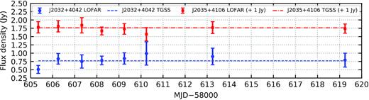
The 143.5-MHz light curves of the two field sources used to investigate the accuracy of our bootstrapping procedure (see Fig. 1). The dashed lines are the 147.5-MHz TGSS catalogue values. Flux densities for J203533.2+410645 have been shifted upwards by 1 Jy for the purposes of clarity. Error bars are ±1σ. As in Fig. 2, the assumed 20 per cent uncertainty in the absolute flux density scale is not accounted for in the plotted error bars.
Given the proximity of Cygnus A to our target, the standard 10 per cent TGSS calibration uncertainty may not necessarily have been applicable in this study (H. Intema, priv. comm.). We were therefore more conservative and assumed the TGSS flux density scale accuracy to be 20 per cent for our target field. As an additional reliability check, we took the five bright comparison sources that we used to bootstrap the flux density scale from TGSS, and found their higher-frequency counterparts in the 1400-MHz NRAO VLA Sky Survey (NVSS; Condon et al. 1998). The median TGSS–NVSS two-point spectral index (|$\alpha ^{1400}_{147.5}$|) of these sources, −0.79, is encouragingly close to the median for the global TGSS–NVSS cross-correlation (−0.73; Intema et al. 2017).
APPENDIX B: INVESTIGATING THE POSSIBLE CONTRIBUTION TO THE LOFAR FLUX DENSITIES FROM NEARBY EXTENDED EMISSION
Sánchez-Sutil et al. (2008) reported on the detection of low-surface-brightness, arcminute-scale emission in the vicinity of Cygnus X-3. The integrated flux density at 5 GHz is 133 mJy, and α ≈ −0.5. This emission would have been significantly blended with Cygnus X-3 at the angular resolution of our LOFAR observations. Extrapolating the 5-GHz flux density to 143.5 MHz using α = −0.5 gives a 143.5-MHz flux density of roughly 800 mJy. However, it is unclear whether this emission follows a single-power-law spectrum to LOFAR frequencies. On the one hand, no corresponding detection was seen in TGSS (3σ upper limit ≈ 30 mJy beam−1; angular resolution 25 arcsec), but this could have possibly been due to limitations in the low-surface-brightness sensitivity of this survey (Intema et al. 2017). On the other hand, Miller-Jones et al. (2007) detected diffuse emission in the vicinity of Cygnus X-3 at a frequency of 330 MHz (left-hand panel of their figure 3; synthesized beam 93 × 59 arcsec2 and PA 3|${_{.}^{\circ}}$|3); also see the 325-MHz detection in Benaglia et al. (2021). We inspected the corresponding image file (J. Miller-Jones, priv. comm.), finding that the surface brightness increased at the same coordinates as the feature reported by Sánchez-Sutil et al. (2008), with a brightness level of about 15–25 mJy beam−1. A very crude, non-background-corrected estimate of an upper limit for the 330-MHz integrated flux density of the extended emission is ∼90 mJy. This upper limit is well below what would be expected based on a single-power-law extrapolation from 5 GHz assuming α = −0.5, suggesting that the spectrum of the extended emission has turned over at low frequencies due to one or more absorption processes. The corresponding flux density at 143.5 MHz could therefore be even lower, well within the uncertainties for the Cygnus X-3 measurements reported in Table 1.
APPENDIX C: MODELLING THE SPECTRAL TURNOVER: FULL SET OF RESULTS
In Table C1, we present the results from the spectral turnover modelling that we described in Section 5.3, for all eight observing runs.
Spectral modelling results for all eight runs. See the caption in Table 3 for further details.
| Run and | νp | ντ | Sτ | |$\chi ^2_{\rm red}$| |
|---|---|---|---|---|
| Type of fit | or νRT | or SRT | ||
| (MHz) | (MHz) | (Jy) | ||
| 1; SSA | 490 | 360 ± 30 | 13.6 ± 0.7 | 0.23 |
| 1; FFA mixed | 550 | 410 ± 40 | 12.7 ± 0.7 | 0.47 |
| 1; FFA foreground | 440 | 240 ± 10 | 10.3 ± 0.3 | 0.53 |
| 1; RT effect | 630 | 360 ± 20 | 9.8 ± 0.3 | 21 |
| 2; SSA | 530 | 400 ± 30 | 13.9 ± 0.6 | 0.15 |
| 2; FFA mixed | 600 | 460 ± 40 | 13.0 ± 0.6 | 0.44 |
| 2; FFA foreground | 450 | 250 ± 10 | 10.9 ± 0.3 | 0.39 |
| 2; RT effect | 700 | 420 ± 20 | 10.1 ± 0.2 | 28 |
| 3; SSA | 480 | 340 ± 40 | 13.9 ± 0.7 | 0.038 |
| 3; FFA mixed | 540 | 390 ± 50 | 13.2 ± 0.7 | 0.17 |
| 3; FFA foreground | 450 | 230 ± 10 | 10.2 ± 0.3 | 0.22 |
| 3; RT effect | 630 | 320 ± 30 | 10.2 ± 0.3 | 16 |
| 4; SSA | 550 | 360 ± 30 | 11.2 ± 0.4 | 4.1 |
| 4; FFA mixed | 640 | 420 ± 40 | 10.7 ± 0.4 | 3.9 |
| 4; FFA foreground | 500 | 230 ± 10 | 7.9 ± 0.2 | 4.0 |
| 4; RT effect | 870 | 360 ± 20 | 8.1 ± 0.2 | 21 |
| 5; SSA | 530 | 370 ± 30 | 17.3 ± 0.7 | 0.13 |
| 5; FFA mixed | 600 | 430 ± 40 | 16.3 ± 0.7 | 0.34 |
| 5; FFA foreground | 470 | 240 ± 10 | 12.8 ± 0.3 | 0.33 |
| 5; RT effect | 760 | 380 ± 20 | 12.5 ± 0.3 | 21 |
| 6; SSA | 500 | 390 ± 40 | 21.1 ± 1.2 | 12 |
| 6; FFA mixed | 550 | 430 ± 40 | 19.7 ± 1.2 | 13 |
| 6; FFA foreground | 430 | 250 ± 10 | 16.7 ± 0.5 | 13 |
| 6; RT effect | 610 | 400 ± 20 | 15.1 ± 0.4 | 42 |
| 7; SSA | 340 | 270 ± 20 | 15.6 ± 0.9 | 1.1 |
| 7; FFA mixed | 360 | 290 ± 30 | 14.7 ± 0.9 | 1.2 |
| 7; FFA foreground | 340 | 200 ± 10 | 11.3 ± 0.5 | 1.4 |
| 7; RT effect | 380 | 260 ± 30 | 10.4 ± 0.6 | 8.2 |
| 8; SSA | 250 | 200 ± 20 | 9.3 ± 0.7 | 0.37 |
| 8; FFA mixed | 260 | 210 ± 20 | 8.9 ± 0.7 | 0.38 |
| 8; FFA foreground | 250 | 160 ± 20 | 6.7 ± 0.5 | 0.44 |
| 8; RT effect | 210 | 170 ± 30 | 6.8 ± 0.9 | 1.8 |
Author notes
Deceased.
