


ABSTRACT
In this paper, we investigate the impact of correlated noise on fast radio burst (FRB) searching. We found that (1) the correlated noise significantly increases the false alarm probability; (2) the signal-to-noise ratios (S/N) of the false positives become higher; (3) the correlated noise also affects the pulse width distribution of false positives, and there will be more false positives with wider pulse width. We use 55-h observation for M82 galaxy carried out at Nanshan 26m radio telescope to demonstrate the application of the correlated noise modelling. The number of candidates and parameter distribution of the false positives can be reproduced with the modelling of correlated noise. We will also discuss a low S/N candidate detected in the observation, for which we demonstrate the method to evaluate the false alarm probability in the presence of correlated noise. Possible origins of the candidate are discussed, where two possible pictures, an M82-harboured giant pulse and a cosmological FRB, are both compatible with the observation.
1 INTRODUCTION
Fast radio bursts (FRBs) are bright (50mJy–100Jy) millisecond-duration bursts observed in radio frequency as initially noticed by Lorimer et al. (2007). The FRB signals, propagating through ionized medium, usually show frequency-dependent dispersion features following the cold-plasma dispersion relation, i.e. the pulses in high-frequency band arrive earlier than those in low frequency. The time delay between high and low frequency (νhigh and νlow) is |$\Delta t=4.15\, {\rm ms}\, \times {\rm DM} (\nu _{\rm low, GHz}^{-2}- \nu _{\rm high, GHz}^{-2})$|, where DM is the electron column density along the line of sight in the unit of |$\rm cm^{-3}\, pc$|. The observed DM values of FRBs usually exceed those allowed by the Milky Way, which indicates the FRB sources are at extragalactic or cosmological distances. About 120 FRBs had been detected (Petroff et al. 2016),1 and more than 20 of them reported to repeat (Spitler et al. 2016; CHIME/FRB Collaboration 2019a, b; Kumar et al. 2019; Luo et al. 2020a). Recently, the origin of an FRB had been successfully traced to the magnetosphere of a magnetar (Bochenek et al. 2020; CHIME/FRB Collaboration 2020; Luo et al. 2020c), yet the burst trigger mechanism is still unknown (Lin et al. 2020).
FRBs have significant astrophysical applications, which cover a wide range of topics, e.g. testing the Einstein’s equivalence principle (Wei et al. 2015; Tingay & Kaplan 2016; Zhang 2016), constraining the rest mass of photons (Bonetti et al. 2016, 2017; Wu et al. 2016; Shao & Zhang 2017), revealing hidden baryons in the Universe (McQuinn 2014; Macquart et al. 2020), studying the dark-energy equation of states (Zhou et al. 2014), and probing the cosmological matter distribution (Masui & Sigurdson 2015).
Finding a larger sample of FRBs is the key to understand the FRB burst trigger mechanism and to probe the astrophysics. The FRB searching is thus one of the most important observational activities in the field. Although FRBs are bright bursts, their short durations limit the signal-to-noise ratio (S/N). In order to detect FRBs, most of the FRB searching algorithms are to optimize the FRB detection in the presence of radiometer noise (Cordes & McLaughlin 2003; Men et al. 2019). The matched filter being used in those investigations is the most powerful statistics for detecting burst signals with the pre-determined waveforms (Vaínshteín & Zúbakov 1970). It is asymptotically optimal (Van der Vaart 2000), i.e. it archives the best possible detection ability, when the S/N is large. Indeed, several FRB searching softwares use box-car matched filter as the burst signal detectors, e.g. heimdall 2 and bear (Men et al. 2019). Two major key assumptions of the matched filter approach in signal detection are (1) the waveform of the signal to be detected is known and (2) the statistical properties of the noise are known. The performance of the detector thus depends closely on the noise model.
One of the major obstacles in FRB searching is the interference in radio band. The radio frequency interferences (RFIs) can mimic the FRB features in terms of the intensity, pulse width, and dispersion feature (Burke-Spolaor et al. 2011). Men et al. (2019) had detected an RFI which resembles the FRB signal very well. Significant efforts had been applied to reduce the impact of RFIs on FRB searching. For example, methods such as RFI mitigation and machine learning in FRB candidate sifting had both reduced the number of false positive detections (Zhang et al. 2018; Agarwal et al. 2020; Zhang et al. 2020). For strong RFIs, one usually mitigates the effects by subtracting them from data. Weak RFIs, on the other hand, are hard to be subtracted. Hence, the correlated noise (or coloured noise) will be left in the data.
The correlated noise is well known in radio astronomy, and it may emerge from many different processes, e.g. flicker noises (Press 1978), propagation effects (Gwinn & Johnson 2011), signal-chain gain instability (Gallego et al. 2004), and low level RFIs (Dewey 1994). Investigating the origin of the correlated noise in FRB searching data is beyond the scope of this paper. Here, we focus on the impact of the correlated noise on FRB searching.
We will show in Section 2 that the correlated noise increases the false alarm probability for FRB detection dramatically, and the distribution function of the burst parameters will also be affected. We will investigate the S/N and pulse width distribution of the false positives. We use real observational data to illustrate the application of the correlated noise modelling in Section 3, where we also discuss the evaluation of false alarm probability for single event, where a potential FRB candidate found during the observation of the M82 galaxy is used as an example. Discussions and conclusions are made in Section 4.
2 DETECTION STATISTICS
The relation between white-noise-only false alarm probability Pf and the one including the coloured noise component is plotted in Fig. 1. One can see that the false alarm probability computed using the equation (2) will be underestimated, if the signal contains coloured noise. The larger the η is, the more one will underestimate the false alarm probability. That is, a high value of S may come from correlated noise contribution rather than from real burst signals.

As shown in equation (4), two factors play the roles: (1) the amplitude of the coloured noise (σr) and (2) the number of data points (Nbox) within the given pulse. One can see that a higher RMS level of coloured noise or a wider pulse introduces a larger bias on the false alarm probability computation. Nbox in equation (4) reflects the fact that a wider pulse (corresponding to a lower frequency in frequency-domain spectrum) contains more coloured noise contributions. For a typical case, the data sampling time-scale is about 100 μs and the FRB signal lasts for a few milliseconds, Nbox ∼ 10–102. Considering κ ≃ 0.01, the red noise component plays a significant role, when its RMS level is compatible with the white noise.
3 A REPRESENTATIVE EXAMPLE
3.1 Observation and data reduction
We now show the application of the above theory. The data for the demonstration were taken with Nanshan 26-m (NS26m) radio telescope, which was observing the M82 galaxy at that time. The NS26m is operated by Xinjiang Astronomical Observatory (XAO) of Chinese Academy of Science. Its location is N43°28.27′, E87°10.67′ with the altitude of 2080 m (Wang et al. 2001). We perform observations centred at 1560 MHz with bandwidth of 320 MHz, i.e. from 1.4 to 1.72 GHz. NS26m has a cryogenic front-end and the total system temperature is 25 K. The radio frequency signal is down converted to intermediate frequency of 100–420 MHz with a local oscillator at 1300 MHz.
We also used data collected from the Kunming 40-m (KM40m) and the Haoping 40-m (HRT) radio telescopes. KM40m is operated by Yunnan Astronomical Observatory, Chinese Academy of Sciences. It locates at N25°02′, E102°47′ with the altitude of 1985 m (Hao, Wang & Yang 2010). We use C-band (6.7 GHz) data of KM40. The HRT at Haoping (N34°, 10.5′ E109°56.97′) (Luo et al. 2020b) is operated by National Time Service Center, Chinese Academy of Sciences. The electronic specification and observation configuration of the telescopes are given in Table 1.
Set-ups at NS26m, KM40m, and HRT for M82 observation.
| Telescope | BW | |$f_{\textrm {central}}$|a | |$f_\textrm {ch}$|b | Gain | |$T_\textrm {sys}$|c | |$\Delta t$| d |
|---|---|---|---|---|---|---|
| MHz | MHz | MHz | |$\rm {K\, Jy}^{-1}$| | K | |$\rm \mu s$| | |
| NS26m | 320 | 1560 | 0.97 | 0.1 | 25 | 65 |
| KM40m | 440 | 6690 | 0.2 | 0.2 | 96 | 65 |
| HRT | 800 | 1400 | 0.097 | 0.2 | 100 | 163 |
Notes.
Central frequency of observation.
Channel width.
System temperature.
Time resolution.
We use the Reconfigurable Open Architecture Computing Hardware 2 3 based system to digitize the signal at NS26m, where we form 1024 channels using polyphase filter and integrate the intensity to form filterbank data with 65 |$\rm {\mu s}$| sampling time. The filterbank data packets are then transferred to a data recording computer using 10 Gigabit Ethernet.
We observed M82 with NS26m for five times from 2016 to 2017. The total observing time is 55 h. The FRB searching is performed in realtime using the software package Burst Emission Automatic Roger(bear, Men et al. 2019). In bear, RFI mitigation, de-dispersion, box-car matched filter pulse detection, and candidate clustering are performed. There are two RFI mitigation steps in our pipeline: we first remove data of the channels around 1.55 GHz, because of the RFI induced by satellite communication, and then we use the zero-DM matched RFI filter (Men et al. 2019) to remove wideband interference without dispersion features. We further neglect all candidates with DM bellow 200 |$\rm cm^{-3}\, pc$| in our analysis to remove the zero-DM RFI contamination.
The data were downsampled before de-dispersion to reduce the computational cost. The parameter of downsampling is tuned together with the DM steps in de-dispersion. We choose the largest possible DM step such that the pulse smearing induced by DM-mismatching is less than the inter-channel DM smearing. The downsampling time resolution is chosen such that it is also smaller than the inter-channel DM smearing. In this way, we minimize the computational cost without downgrading the minimal width of detectable pulses, and the smearing effects are mainly affected by the inter-channel DM smearing.
Sub-band de-dispersion was used in bear to speed up the computation, where we divided the filterbank data into sub-bands and de-dispersed the data into a coarse grid of trial DMs. The de-dispersed sub-band data are then further de-dispersed to the required fine DM grids (Men et al. 2019). We chose DM range from 200 to 2000 |$\rm cm^{-3}\, pc$|. Our plan of de-dispersion is listed in Table 2. The calculation of the S/N loss is shown in Fig. 2, where one can see that our set-up is sensitive to FRBs with widths larger than 3 ms for |${\rm DM} \lt 2000 {\rm cm^{-3}\, pc}$|.
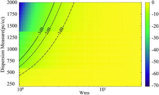
The S/N loss curve caused by sub-band incoherent de-dispersion process. Here, our computation uses NS26m parameters. The S/N loss includes effects of inter-channel DM smearing, searching DM step size, and downsampling. X-axis is the pulse width in ms, and Y-axis is the DM of the source. The S/N loss is given in dB, i.e. |$10\log _{\rm 10}\left(\rm {S/N} \right)$|. The contour lines represent the total S/N loss for 1, 2, and 3 dB.
The de-dispersion plan for data of NS26m.
| DM range | |$\Delta \textrm {DM}$| a | Downsampling | ΔsubDMb | Sub-band | |$\tau _{\rm ch}$| c | |$\tau _{\rm \Delta DM}$| d |
|---|---|---|---|---|---|---|
| (|$\rm cm^{-3}\, pc$|) | (|$\rm cm^{-3} pc$|) | ratio | (|$\rm cm^{-3}\, pc$|) | number | (ms) | (ms) |
| 200.0–300.5 | 0.5 | 4:1 | 8 | 12 | 0.3 | 0.4 |
| 300.5–591.5 | 1.00 | 8:1 | 17 | 17 | 0.6 | 0.7 |
| 591.5–1389.5 | 3.00 | 16:1 | 18 | 45 | 1.2 | 2.0 |
| 1389.5–2004.5 | 5.00 | 32:1 | 18 | 34 | 2.0 | 3.0 |
Notes.
DM step size.
Sub-band DM step size.
Maximal inter-channel DM smearing time-scale.
DM-mismatch smearing time-scale.
After the candidate plots are generated, the plots are visually inspected to see if there is a wideband burst signal with a dispersive signature. There are about 1.4 × 10⁴ candidates generated with S/N ≥ 7. The multidimensional distributions for the candidate parameters S/N, width, and DM are shown in Fig. 3. Four notable features in Fig. 3 are topic-related for the discussion later in the paper: (1) the candidate number is much larger than expected; (2) the candidate S/N distribution shows long-tailed feature; (3) candidate counts correlate with the pulse width; (4) S/N correlates with the pulse width.
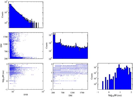
Candidate distribution of NS26m for DM, pulse width Wms and S/N. Here, we only include the candidates with S/N ≥ 7. The diagonal histograms are one-dimensional distributions for each parameter, i.e. S/N, DM, and logarithmic pulse width. The off-diagonal scatter plots are for the two-dimensional distributions of parameter pairs. A few peaks in DM distribution, i.e. around DM ≃ 300, 600, and 1400, are due to our de-dispersion plan as shown in Table 2. On the boundaries of the de-dispersion plan, bursts were searched ‘twice’, as the de-dispersion plan segmentation overlaps. Furthermore, if the true DM of a burst is slightly outside the de-dispersion range, the searched DM value is forced to be on the boundary. In this way, high S/N candidates further pile up on the DM boundaries.
Those four features are unexpected in white Gaussian noise modelling (Cordes & McLaughlin 2003; Men et al. 2019). To understand the four features, we need to characterize the correlated noise. We measured the correlated noise spectrum by performing windowed spectral analysis on zero-DM one-dimensional time series. The data were divided into a number of 1 s segments, and the Hamming windowed Fourier transform (Harris 1978) was applied to estimate the spectral density. The spectral density of all the data is collected in Fig. 4. As one can see that the average spectrum is dominated by low-frequency correlated noise, and the spectral density drops as the frequency increases, only at frequency above a few kHz, the spectral density curve gradually turns flat. Obviously, the false alarm probability will be underestimated, if we use the white-noise-only model.
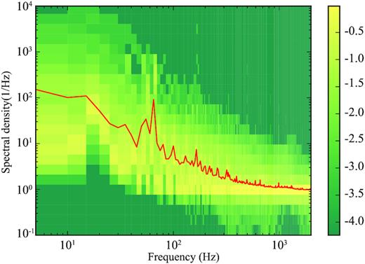
The noise spectrum of 0-DM time series. The x-axis is the frequency in Hz, and the y-axis is the spectral density estimated using Hamming windowed Fourier transform. The red solid curve is the average of all spectra. The background colour scale is the 10-based logarithmic probability of occurrence for the noise power as the given frequency and spectral density. The colour bar on the right side indicates the probability.
The intensity and shape of red noise spectrum fluctuate time-to-time, as indicated by the background colour shade in Fig. 4. The data can be ‘white’ or ‘red’ for a short duration. Since, by average, the red noise dominates the noise spectrum, we have η ≃ 1 + Nboxκ ∼ 1 + 0.01Nbox.
We can check the distribution of all-candidate S/N as shown in Fig. 5. The distribution of detected candidates deviates from the χ2 distribution, because the expected S is higher for pulses with larger width. The wider pulses will induce a higher S/N distribution tail. The measured distribution indeed has a tail extending to higher S/N. The false alarm probability will be underestimated, if one assumes χ2 distribution, i.e. equation (2). The correct version of false alarm probability can be computed by including the correlated noise modelling, i.e. by using equation (5). As one can see in Fig. 5, equation (5) produces S/N distribution similar to what we see in the data.
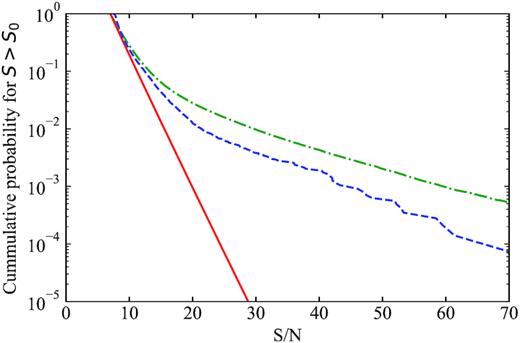
The relation between S/N and cumulative probability for candidates with S ≥ S0. The x-axis is the S/N, i.e. |$\sqrt{S}$|, and the y-axis is the cumulative probability for S ≥ S0. The measured cumulative distribution is plotted in blue dashed curve. The red solid curve is computed from the χ2 distribution, i.e. equation (2). The green dash–dotted curve is computed from equation (5), which includes the correlated noise contribution.
We also note that the pulse width is correlated with the detection statistic S, which reflects the coloured noise effect. As shown in Fig. 6, there seems to be an increase of S/N with larger pulse width. For pure white noise modelling, the correlation is not expected. After including the coloured noise, i.e. equation (5), we can understand such a correlation.
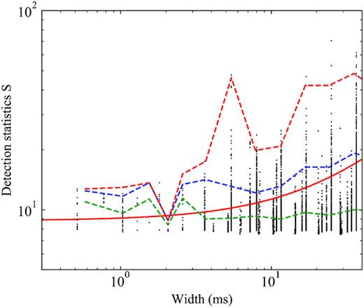
The relation between pulse width (x-axis) and detection statistic (y-axis). The black dots are for all candidates found in observation. The solid line in green shows the average value of the detection statistic as a function of pulse width, while the solid blue and red curve are the 95 per cent and 99.7 per cent envelope. The corresponding curves in dash lines are the same curve computed from red noise modelling, i.e. from equation (5).
3.2 An interesting candidate
For 55 h data, all candidates with S/N≥5 were visually inspected. Particularly, volunteers had helped to perform the visual inspection of all candidates more than once. We organized the visual inspection campaign by collaborating with Bayesian Data Technologies (Wuhan) Co., Ltd (BDT). BDT helped to remove the axes of candidate figures, and embedded the candidate plots into their mobile game Lighthouse Project, aiming at popularizing science.4 The players of the game are encouraged to acquire more credits by identifying the contents of figures. In the game, the players need to first pass a training session. In the session, examples of known FRB signals were shown to the players together with explanation of the contents. Common concepts in astronomy are introduced, e.g. dispersion, frequency, and intensity. In this way, the players can understand what were shown to them. After the training, candidate plots were shown, and the players started to help identify the FRB signals. Each candidate plot was passed to several players, and BDT helped to identify the common votes from players. We also tested whether there are candidates being missed by the volunteers. This is done by showing known FRB signals to the players, and the ‘performance’ of each player can be evaluated by computing the probability of missing true FRBs.
With the help of volunteers, we also looked at those weaker bursts with 5 ≤ S/N ≤ 7. We found one interesting candidate within the entire 55 h NS26m observation. The pulse profile, de-dispersed dynamical spectra, and S/N-DM-t diagnosis plot of the candidate is shown in Fig. 7. More details can be found in Appendix B. The candidate exhibits wideband emission, ‘−2’-index DM signature, but with low S/N. Those properties make it hard investigate the origin of the candidate. It can be either an RFI or a real FRB. We estimated the flux and fluence of the burst to be 0.6 Jy and 7 |${\rm Jy\, ms}$|, using the gain (0.1K/Jy), system temperature (25 K) of NS26m, and effective bandwidth of 280 MHz after RFI mitigation.
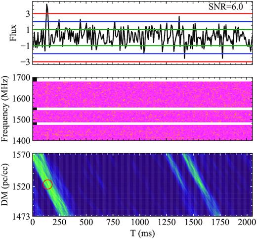
Dynamical spectra of a weak burst (S/N ≃ 6, after RFI zapped) detected with NS26m telescope (320MHz). Top: normalized pulse profile. The pulse width is approximately 9 ms. Middle: dynamical spectrum of the pulse. The pulse has been de-dispersed to DM 1522.8 pc cm3 to get maximal S/N = 6. We reduce the number of frequency channel to 82 (channel width of 3.9 MHz) and time resolution to 1.15 ms, the total effective bandwidth is 280 MHz. After de-dispersing with cold-plasma dispersion relation, i.e. f−2-law, the signal in each channel are aligned in time. Bottom: S/N as a function of time and DM trials. The red circle indicates the pulse position in DM-time parameter space.
The pulse may come from statistical fluctuations. The S/N of the pulse is 6.0, which corresponds to S = 36 and Pf ≃ 2 × 10⁻⁹ for pure white noise case. Given the pulse width of 9 ms and total 55 h observation time, there will be 2.2 × 10⁷ independent 9-ms segmentations. Thus, if only the white noise is considered, one will expect the chance to find such a ‘burst’ due to the accidental statistical fluctuation is about |$1{{\ \rm per\ cent}}$|. As we have shown in the previous section, red noise would increase the apparent S and significantly increase the false alarm probability. Could the candidate be caused by the red noise then? We extracted 8-s data around the burst, and measured the noise power spectrum of zero-DM time series. The spectral density is plotted in Fig. 8. We estimate the white noise contribution by fitting a horizontal line for frequency above 100 Hz. We then measured the red noise contribution, by subtracting the white noise component from the total spectrum. For the 8-s data around the pulse, the red noise component contribution is only about |$6{{\ \rm per\ cent}}$| of total power, i.e. |$\sigma _{\rm r}^2/(\sigma ^2+\sigma _{\rm r}^2)\simeq 6{{\ \rm per\ cent}}$|. The data around this pulse seem to be less affected by red noise. According to equation (4), red noise is incapable of affecting the S estimation significantly. We should be able to trust the 6|$\sigma \, {\rm S/N}$| and 1 per cent false alarm probability for 55-h observation. From probability point of view, it is preferred that the burst is real and not from statistical fluctuation.
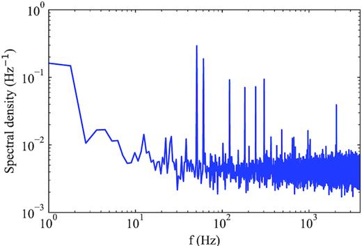
The noise spectrum of the data shown in Fig. 7. The x-axis is the frequency, and the y-axis is the power spectrum density. Besides the white noise components (horizontal part with frequency higher than 100 Hz), there are low-frequency red noise components together with several periodic components, which may come from RFIs. By subtracting the white noise component, we measured that the ratio between red noise power and total noise power is |$\sigma _{\rm r}^2/(\sigma ^2+\sigma _{\rm r}^2)\simeq 6{{\ \rm per\ cent}}$|, with sampling time of 130 μs.
Follow-up observations for the source were carried out using KM40m and HRT. We observed 12 h with KM40m on 2019 November 8 using 6.7 GHz centre frequency, and 12 h with HRT on 2019 December 30 at 1.4 GHz centre frequency. Unfortunately, neither HRT nor KM40m detected any convincing pulse in the DM range from 1520 to 1526 |$\rm cm^{-3}\, pc$| with S/N≥6, and the flux limits are |$\le 1.4\:{\rm Jy\, (1.4 \:GHz)}$| and |$0.7\:{\rm Jy\, (6.7 \:GHz)}$|, respectively, assuming the pulse width of 9 ms as measured by NS26m.
4 DISCUSSION AND CONCLUSION
In this paper, we investigate the effects of correlated noise in the false alarm probability computation for FRB detection problem. In the presence of correlated noise, particularly red noise, the false alarm probability becomes larger than the case where only white noise is included. The correlated noise also introduces a dependence of false alarm probability on the pulse width. Particularly, for the red noise case, one will detect more candidates with larger pulse width. We have also used observation carried out at NS26m radio telescope to show the application of the false alarm probability computation. We can reproduce the expected number of candidates and their statistical properties. We also show one interesting candidate found in M82 observation.
The burst appears in the direction of M82, however we cannot directly associate the burst with M82. The beam size (in solid angle) of NS26m is roughly 16 times of the angular size of M82 (approximately 11.6 arcmin × 3.7 arcmin; Jarrett et al. 2003). In fact, NASA/IPAC Extraglaxtic Databases 5 show that there are 1458 known galaxies in the NS26m field of view. If we assume the source resides in M82, given the luminosity distance of 3.6 Mpc for M82, the isotropic peak luminosity of the burst will be Liso ∼ 3 × 1036 erg s−1, which will be four orders of magnitude lower than the average luminosity of known FRBs. The luminosity is compatible with that of bright Crab giant pulses reported by Bera & Chengalur (2019), although the pulse width is at least three orders of magnitude wider than the case of the Crab giant pulse. The luminosity is also similar to the case of SGR J1935+2145 (∼7 × 1036 erg s−1; CHIME/FRB Collaboration 2020; Bochenek et al. 2020), although the pulse width is about 20 times larger than that of SGR J1935+2145 (i.e. 0.5 ms CHIME/FRB Collaboration 2020). If the burst is real, and it is located in M82, it is compatible to the picture that a bright radio burst comes from a magnetar in the M82.
The measured DM (1523 |$\rm cm^{-3}\, pc$|) of the candidate is compatible with both of the two scenarios: (1) a giant pulse from M82, and (2) an FRB at a cosmological distance. The DM contribution from the intergalactic medium between Milky Way and M82 (|$\sim 1\, \rm cm^{-3}\, pc$|, Prochaska & Zheng 2019) is negligible comparing to other contributions, i.e. Galactic foreground of 33 |$\rm cm^{-3}\, pc$| (Yao, Manchester & Wang 2017), halo of Local Group |$\sim 100\, \rm cm^{-3}\, pc$| (Prochaska & Zheng 2019). Thus, the major DM contribution (1400 |$\rm cm^{-3}\, pc$|) results from M82, if M82 association is assumed. As shown by Westmoquette et al. (2007) and Heckman et al. (1990), the electron density in M82 increase from 100 |$\rm cm^{-3}$| at 1–3 kpc outskirt to 1000 |$\rm cm^{-3}$| around the galaxy nucleus. Therefore, the measured DM is compatible with M82 properties in the picture of an M82 hosted source. The other picture, i.e. a cosmological FRB is also possible. If the source is at a further cosmological distance, the source can be much more luminous. Using the model of Luo et al. (2018), the redshift will be |$z=1.3^{+0.03}_{-0.5}$| and the inferred isotropic peak luminosity is |$1.9^{+0.1}_{-1.3} \times 10^{43}\, {\rm erg\,s^{-1}}$|, which is compatible to the properties of the known FRB population (Luo et al. 2018). At this stage, we are lack of further detection, and cannot conclude yet on the nature of the source, as both the M82 and the cosmological interpretation are possible.
In both of the two pictures, there is an event rate issue. If the burst is harboured by M82, the inferred event rate is |$1/55 \simeq 0.02\, {\rm ~h^{-1}}$|. Considering the rareness of radio burst from the Galactic magnetar SGR J1935+2145 and the fact that M82 is smaller in stellar number compared to the Milky Way, the inferred event rate value seems to be too high. If the burst is cosmological, we would expect to detect 10−2–10−3 FRB per day with NS26m (Luo et al. 2020a), which is still much lower than our inferred event rate. However, the star formation rate in M82 is a few times higher than that in the Milky Way (Kennicutt & Evans 2012), which may indicate that the event rate of radio burst phenomenon may correlate with the star formation rate. If so, we would expect more radio bursts can be found by monitoring those starburst galaxies.
ACKNOWLEDGEMENTS
The work is supported by CAS XDB23010200, Max-Planck Partner Group, National SKA program of China 2020SKA0120100, NSFC 11690024, CAS Cultivation Project for FAST Scientific. We also thank active players of the mobile game Lighthouse Project to help perform the candidate inspection, including Y. Zou, H. Y. Lin, J. Q. Li, J. Y. Li, Y. X. Jiang, etc.
DATA AVAILABILITY STATEMENT
The data underlying this article are available in a repository and can be accessed via https://github.com/zhanyige/M82_FRB_couloured_noise/blob/data/original_data.zip
Footnotes
frbcat: http://www.frbcat.org
developed by Andew Jameson and Ben Barsdell, https://sourceforge.net/p/heimdall-astro
REFERENCES
APPENDIX A: STATISTICAL PROPERTIES OF S WITH COLOURED NOISE
We denote the coloured noise component as ri, and white noise component as ni with index i indicating the temporal sampling. The de-dispersed one dimensional time series is si = ri + ni. The summation of si, i.e. |$u\equiv \sum _{|t-t_0|\lt w} s_i$|, follows Gaussian distribution, because a linear superposition of Gaussian variable is still Gaussian. In this way, the detection statistic, being a square of Gaussian (S∝u2), must follow a one dimensional scaled χ2 distribution.
APPENDIX B: bear DETECTION PLOT
In this section, we show the bear candidate sifting plot for the signal we found, i.e. Fig. B1. As one can see from sub-panel (j), the signal is contributed from channels across rather wide bandwidth. Sub-panel (h) shows that the burst cannot be found in the zero-dm time series, which verify the dispersive nature of the burst, and sub-panel (g) further indicates that the DM index is around −2.
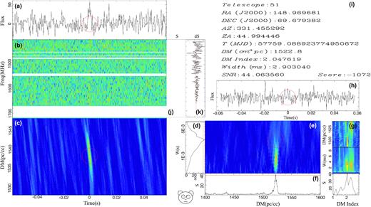
An FRB candidate found along the M82 direction. The plot is produced by bear. (a) the de-dispersed candidate pulse profile with a red circle indicating the pulse time of arrival, (b) the dynamical spectrum after de-dispersion, (c) the likelihood ratio test statistics S as a function of DM and time, (d) S as a function of pulse width, (e) S as a function of DM (x-axis) and pulse width (y-axis), the red circle label the best estimated DM value, (f) S as a function of DM, where the red horizontal lines indicate false alarm rate of 10−10, (g) DM, pulse width and S as a function of DM index, (h) the time series de-dispersed at 0 DM, (i) the basic information of the pulse, (j) the integration of S(x-axis) changes over frequency channel, (k) the contribution of S from each frequency channel.
