


ABSTRACT
We observed the Brackett α emission line (4.05 μm) within the nuclear starburst of NGC 253 to measure the kinematics of ionized gas, and distinguish motions driven by star formation feedback from gravitational motions induced by the central mass structure. Using NIRSPEC on Keck II, we obtained 30 spectra through a |$0^{\prime \prime }_{.}5$| slit stepped across the central ∼5 arcsec × 25 arcsec (85 × 425 pc) region to produce a spectral cube. The Br α emission resolves into four nuclear sources: S1 at the infrared core (IRC), N1 at the radio core, and the fainter sources N2 and N3 in the northeast. The line profile is characterized by a primary component with Δvprimary ∼90–130 |$\rm km\, s^{-1}$| (full width at half-maximum) on top of a broad blue 2wing with Δvbroad ∼300–350 |$\rm km\, s^{-1}$|, and an additional redshifted narrow component in the west. The velocity field generated from our cube reveals several distinct patterns. A mean NE–SW velocity gradient of +10 |$\rm km\, s^{-1}$| arcsec−1 along the major axis traces the solid-body rotation curve of the nuclear disc. At the radio core, isovelocity contours become S-shaped, indicating the presence of secondary nuclear bar of total extent ∼5 arcsec (90 pc). The symmetry of the bar places the galactic centre, and potential supermassive black hole, near the radio peak rather than the IRC. A third kinematic substructure is formed by blueshifted gas near the IRC. This feature likely traces a ∼100–250 |$\rm km\, s^{-1}$| starburst-driven outflow, potentially linking the IRC to the galactic wind observed on kpc scales.
1 INTRODUCTION
The nuclear regions of disc galaxies are singular environments, in the sense that they serve as a distinct destination for the inward flow of matter in disc galaxies. Internal secular processes shape the continuing evolution of present-day disc galaxies (Kormendy & Kennicutt 2004). Radial gas flow induced by non-axisymmetric structures such as bars, together with star formation and feedback from active galactic nuclei (AGN), all serve to shape a constantly evolving central mass structure in spiral galaxies.
Due to the inward flow of gas, barred galaxies often host intense nuclear star formation or starbursts, often taking the form of nuclear rings of super star clusters (SSCs; e.g. Athanassoula 1984; Buta & Combes 1996; Buta 1999; Böker et al. 2008; Comerón et al. 2010), as predicted by simulations (Athanassoula 1992; Shlosman 2002; Regan & Teuben 2003; Li, Shen & Kim 2015; Sormani et al. 2018; Seo et al. 2019). Star formation in barred galaxies can serve as a sink of the inwardly drifting gas, thus preventing this gas from reaching a central supermassive black hole. However, star formation is never a pure gas sink; it is inefficient and can disperse gas via winds. Young SSCs are likely responsible for the multiphase, large-scale galactic winds observed in starburst galaxies (e.g. Heckman 2001). Hydrodynamic simulations of barred galaxies find that such intense feedback can shape the growth of galactic bulges (e.g. Athanassoula, Machado & Rodionov 2013; Renaud et al. 2013; Li et al. 2015; Carles et al. 2016; Seo et al. 2019). AGN feedback from an accreting SMBH can also regulate star formation in the galactic centre and its host bulge (e.g. Robichaud et al. 2017). On the other hand, remnant, post star-forming molecular clouds can potentially assist the inward drift of their natal embedded clusters via a nuclear bar (Tsai et al. 2013). These are only a few of the possible effects governing gas flows and secular evolution in the centres of disc galaxies.
To investigate the processes of gas inflow and feedback in a barred galaxy, we have studied ionized gas kinematics in NGC 253, one of the closest starburst galaxies (D = 3.5 Mpc; Rekola et al. 2005). NGC 253 is a nearly edge-on (i = 78.5°) spiral with a strong bar that feeds its nuclear starburst (e.g. Scoville et al. 1985; Arnaboldi et al. 1995; Peng et al. 1996; Engelbracht et al. 1998; Das, Anantharamaiah & Yun 2001; Paglione et al. 2004; Meier et al. 2015; Ando et al. 2017). The central ≲200 pc region drives a galactic superwind to a distance of ∼10 kpc at hundreds of |$\rm km\, s^{-1}$| (Strickland et al. 2002; Weaver et al. 2002; Westmoquette, Smith & Gallagher 2011; Bolatto et al. 2013; Walter et al. 2017). The starburst region hosts two regions that could host the forming galactic centre: the radio core with the brightest radio source in the galaxy (TH2; e.g. Turner & Ho 1985; Ulvestad & Antonucci 1997), and the infrared core (IRC; e.g. Watson et al. 1996; Kornei & McCrady 2009). There are a number of candidate large star clusters detected as radio or submm knots and associated molecular gas clumps, near the radio and IRC (Turner & Ho 1983, 1985; Ulvestad & Antonucci 1997; Leroy et al. 2018; Mangum et al. 2019).
The gas velocity fields of the nuclear region of NGC 253 are complex, resulting from combinations of distinct dynamical origin. The extended ionized gas takes the form of a wind that accelerates with distance from the galaxy (Westmoquette et al. 2011). At radii ∼10 arcsec ≃170 pc, the ionized gas kinematics are consistent with solid-body rotation of the nuclear disc, with a velocity gradient along the galaxy major axis position angle (PA) = 51°. However, at the radio core and to a lesser extent the IRC, the velocity field is dominated by a distinct pattern with a gradient nearly perpendicular to the major axis (Anantharamaiah & Goss 1996; Das et al. 2001; Rodríguez-Rico et al. 2006). These authors suggest that this central structure could trace outflow, an accreted object, or a secondary nuclear bar. The NGC 253 starburst powers a molecular outflow near the IRC (Strickland et al. 2002; Weaver et al. 2002; Bolatto et al. 2013; Walter et al. 2017). Kinematic evidence for nuclear outflow near the IRC were seen in high-resolution Brackett γ observations by Günthardt et al. (2015, 2019); however, the location of the dynamical centre of the galaxy remains ambiguous. Severe dust extinction (AV ≳ 20) greatly complicates kinematic analysis of optical near-IR (NIR) gas tracers.
In this project, the goal was to determine the dynamics of ionized gas in the starburst nucleus of NGC 253 and the forming star clusters using an emission line that is bright and relatively impervious to extinction. To this end, we observed the nucleus of NGC 253 with NIRSPEC on Keck II, obtaining slit-spectra of the Brackett α emission at 10 |$\rm km\, s^{-1}$| resolution. Simultaneous imaging of the slit with slit-viewing camera (SCAM) allow registration of the slits spatially with respect to NIR continuum emission. The resulting spectral cube covers the central ∼5 arcsec × 25 arcsec (90 × 360) region with a |$0^{\prime \prime }_{.}5$| slit, or |$\sim 8.5~\rm pc$| at 3.5 Mpc.
2 OBSERVATIONS AND DATA
We observed NGC 253 with NIRSPEC on Keck II (McLean et al. 1998) in the first half-night on 2017 December 7. Observing parameters and properties of NGC 253 are reported in Table 1. Spectra were taken in high-resolution (echelle) mode in the KL band, using the |$0^{\prime \prime }_{.}432$| × 24 arcsec slit. The echelle and cross-disperser angles were set to 64.42° and 34.3°, respectively, yielding a wavelength coverage of 4.031–4.086 μm in the 19th echelle order. The seeing ranged between |$0^{\prime \prime }_{.}7$| and |$1^{\prime \prime }_{.}1$|.
Properties of NGC 253 and its two brightest nuclear sources, along with the NIRSPEC observing parameters.
| Distance and angular scale | 3.5 Mpc; 1 arcsec = 17 pc(1) |
| Inclination of galactic disc i | 78.5°(2) |
| PA of disc major axis ϕd | 51° |
| PA of bar major axis / x1 orbits ϕb, 1 | 70° |
| PA of bar minor axis / x2 orbits ϕb, 2 | 45° |
| Systemic velocity (heliocentric) vsys | 226 |$\rm km\, s^{-1}$|(3) |
| Ionized galactic wind inclination i|$\mathrm{ w}$| | 12°(4) |
| PA of galactic wind ϕ|$\mathrm{ w}$| | 140° |
| Opening angle of galactic wind α|$\mathrm{ w}$| | 60° |
| Outflow speed of galactic wind v|$\mathrm{ w}$| | ≳100–300 |$\rm km\, s^{-1}$| |
| Predicted SMBH mass MBH | ∼2 × 10⁷|$\rm M_\odot$|(5) |
| Radio centre, source TH2 (ICRS) | |$00^{\mathrm{h}}47^\mathrm{m}33{^{\rm s}_{.}}18$|, −25°17′|$16^{\prime \prime }_{.}94$|(6) |
| Radio core mass |$M_{\mathrm{dyn}}^{\mathrm{TH2}}$| | ∼7 × 10⁶|$\rm M_\odot$|(7) |
| Infrared centre, IRC (ICRS) | |$00^{\mathrm{h}}47^\mathrm{m}32{^{\rm s}_{.}}99$|, −25°17′|$19^{\prime \prime }_{.}74$|(8) |
| IRC mass |$M_{\mathrm{dyn}}^{\mathrm{IRC}}$| | ∼5 × 10⁵|$\rm M_\odot$|(9) |
| Observing wavelength | |$\lambda _{{\rm Br}\, \alpha } = 4.052$| μm |
| Slit size | |$0^{\prime \prime }_{.}432$| × 24 arcsec |
| Echelle angle | 64.42° |
| Cross-disperser angle | 34.3° |
| Seeing | |$0^{\prime \prime }_{.}7$|-|$1^{\prime \prime }_{.}1$| |
| Velocity resolution | 12 |$\rm km\, s^{-1}$| |
| Mapping Area | ∼18 arcsec ×30 arcsec(10) |
| Total exposure time | 64 min(11) |
| Peak pixel S/N ratio | 7–72(12) |
Notes.(1) Rekola et al. (2005).
(2) Galactic disc and bar properties adapted from Das et al. (2001), Paglione et al. (2004), and references therein.
(3) This paper, Section 3.2.1.
(4) Ionized wind properties from Westmoquette et al. (2011) modelling of H α outflow cone.
(5) Predicted using M–σ relation (Combes et al. 2019) with measured NGC 253 bulge stellar velocity dispersion from Oliva et al. (1995). The presence of a SMBH in NGC 253 is expected but unconfirmed.
(5) Coordinates of radio peak in NGC 253, identified as nonthermal source TH2 in Turner & Ho (1985).
(6) Estimate from Rodríguez-Rico et al. (2006) within r < 7 pc of TH2, using H92 α mapping with a ≲|$0^{\prime \prime }_{.}5$| beam.
(7) Coordinates of IR peak (IRC) from Leroy et al. (2018), their source #5. Coincident with thermal source TH7 (Turner & Ho 1985).
(8) Virial mass estimate from Leroy et al. (2018) using the resolved source size of 2.1 pc.
(9) Size of the NIRSPEC mapping region, with 31 slit positions.
(10) Combined NIRSPEC exposure time for all spectra across the nuclear starburst.
(11) Signal-to-noise ratio (S/N) of the brightest pixel in echelle spectra.
We obtained a total of 31 120 s exposures at slit positions spanning the central ∼18 arcsec × 30 arcsec of the nuclear region, shown in Fig. 1. We initially orientated the slit along the galaxy’s major axis, at PA ≃ 45°. The slit PA drifted with the Earth’s rotation such that the slits for our final exposures were oriented at PA ≃ 80°. Sky spectra were acquired by offsetting away from NGC 253 after the eighth science exposure and again after the final science exposure. Two calibration stars were observed prior to and after completing all NGC 253 observations (HD225200 and HD12365, respectively). Images of the slit on the sky in the K band were simultaneously acquired using the NIRSPEC SCAM. These images allowed for registration of the slits with respect to the NIR background. In this way we were able to build a cube.
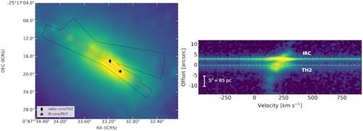
NIRSPEC observations of the starburst in NGC 253. (Left) Stacked SCAM image of the K-band continuum (colour), with the region bounded by all slits in our map (the black outline). The non-thermal source TH2 at the starburst’s radio peak, along with the IR peak in the IRC, is marked by the diamond and the star symbols, respectively. (Right) Reduced 2D echelle spectrum from the single, central slit position highlighted in red on the left. The spectrum runs from NE to SW in the positive vertical direction, with the position of TH2 set as the origin. The brightest Br α emission is detected at the radio core (near TH2) and at the IRC. The spectrum displayed here was combined with the remaining 30 spectra acquired across the region to generate a Br α data cube (Section 2).
Each slit position yielded a 2D echelle spectrum, which we rectified, reduced, and calibrated, using our calibration star spectra along with arc lamp spectra acquired at the beginning of the night. We first subtracted raw NIRSPEC images by sky spectra, divided by a median-normalized flat-field image, and iteratively removed hot/cold pixels. We then spatially and spectrally rectified the images using an Python-based implementation the REDSPEC reduction code.1 The reduced echelle spectra have spatial information in the vertical axis (along the slit) and spectral information in the horizontal axis, as shown by the example spectrum in Fig 1. Each pixel has a size of 5.482 × 10⁻⁵ μm along the spectral axis and |$0^{\prime \prime }_{.}192$|, the nominal value, along the spatial axis. The spectral resolution is about 3 pixel ≃ 12 |$\rm km\, s^{-1}$|.
2.1 The NIRSPEC cube
To take full advantage of our data set, we combined the separate spectra into a spectral cube, with RA/Dec. on the x- and y-axes and wavelength/velocity along the z-direction. Constructing the data cube involved mapping between pixels in each 2D spectrum and pixels on the cube grid, requiring astrometric registration of the slits. Registration was performed by creating a stacked, slit-free SCAM image in which a handful of IR sources are well detected (Fig. 1). To create the stacked image, we sky-subtracted, rotated, and aligned all individual SCAM exposures (showing the slit trace) to a common reference image. We then masked out the slit trace in each image and median-combined all images of acceptable quality. During this process, we tracked the position of each slit, shifting and rotating to the reference image. Once the stacked image was obtained, we measured the pixel positions of detected K-band sources, and matched them with sources with known sky coordinates detected in an archival HST F160W image (Proposal ID 12206, PI Westmoquette), yielding registration of the SCAM image and HST images accurate to ≲|$0^{\prime \prime }_{.}1$| (rms error).
Inferring the pixel mapping for each spectrum requires identification and measurement of a reference point, in addition to the sky positions of the slits (the centre of the slit does not correspond to the centre of the rectified spectrum). As such, we measured the pixel positions of Br α sources in each spectrum that we could match to known sources detected in the NIR imaging, and established the reference pixel required to map spectrum pixel coordinates to sky coordinates.
After registration, we constructed the NIRSPEC cube in the following way. First, we interpolated each echelle spectrum across the slit width, assuming a constant light profile in that direction, and then mapped the data from each pixel in each wavelength slice on to the coordinate frame of the cube. We median-binned the mapped data to a regular grid, and applied smoothing with a Gaussian kernel to remove small-scale artefacts resulting from regions with sparse data. Finally, we interpolated each image slice to the final grid with a spatial scale of |$0^{\prime \prime }_{.}12$| pix−1. The spatial resolution of the cube is ≃|$1^{\prime \prime }_{.}0$|, approximately the same as in individual spectra. A map of the Brackett line emission was generated by fitting continuum-only pixels with a first-order polynomial and subtracting this contribution from the data cube. The Br α cube is shown with channel maps in Fig. 2.
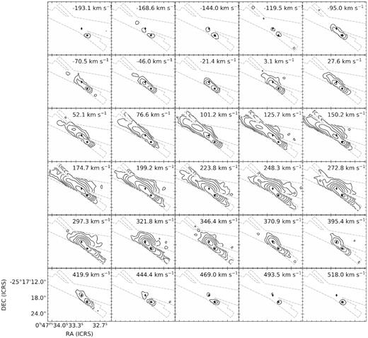
Channel maps of the NIRSPEC Br α cube. To produce this figure, channels are bin-averaged by 6 pixels, to a width of Δv = 24.5 |$\rm km\, s^{-1}$|. Contours show σrms × 2n/4, n = 6, 10, 14, 18, ..., 44, 48, where σrms is the rms noise in channels away from the Br α line. As in Fig. 1, the IRC and TH2 are marked as the star and diamond symbol, respectively. Four Br α sources are identifiable in these maps: a bright peak near IRC that has a broad component visible across all channels, another bright/broad source at the radio core near TH2 with an apparent gradient, a third clump of narrower emission to the NE of TH2 (apparent at 101.2 |$\rm km\, s^{-1}$|), and a fourth clump towards the NE corner of the FoV (apparent at 52.1 |$\rm km\, s^{-1}$|).
3 RESULTS
The cube of Br α emission in the starburst core in NGC 253, shown in Fig. 2, reveals four sources within our slit coverage. We identify these sources as S1, N1, N2, and N3 from the SW to NE along the major axis, and label them on the velocity-integrated Br α intensity map in Fig. 3.
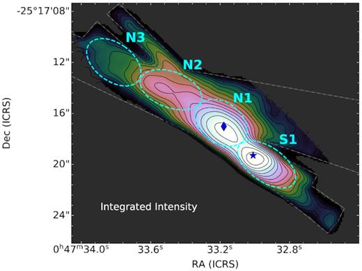
Velocity-integrated Brackett α emission (line flux map) in the core of NGC 253, generated from the NIRSPEC cube by summing pixels at >1.5σrms along the spectral axis. The slit coverage is indicated by the grey outline, and the IRC and TH2 are again marked as the star and diamond symbols, respectively. We detect four likely distinct Brackett sources: N3, N2, N1, and S1 (the cyan-dashed ellipses). The elliptical apertures shown here are used to extract the total spectrum of each source.
Source S1 is at the IRC, a region hosting the starburst’s brightest NIR source, a ∼6 Myr old, M ∼ 106 |$\rm M_\odot$| SSC (e.g. Watson et al. 1996; Fernández-Ontiveros, Kornei & McCrady 2009; Prieto & Acosta-Pulido 2009; Davidge 2016; Günthardt et al. 2019). Several other candidate SSCs are identified near the bright SSC as fainter thermal IR-radio continuum knots (e.g. Fernández-Ontiveros et al. 2009; Günthardt et al. 2015; Leroy et al. 2018). Broad recombination lines suggest an ionized outflow driven by the SSC formation near the IRC (Günthardt et al. 2019). We assume Brackett source S1 primarily traces the H ii region excited by the bright SSC in the IRC, with small contributions from fainter H ii regions around nearby clusters.
Source N1 is associated with the radio core, which contains the galaxy’s brightest radio source, TH2 (Turner & Ho 1985). TH2 is characterized by non-thermal radio continuum with brightness temperature ≳50 000 K (Turner & Ho 1983, 1985; Ulvestad & Antonucci 1997), and no clear infrared counterpart (Günthardt et al. 2015), thus is unlikely to be an H ii region. While its origin remains unclear, the bright radio source TH2 is potentially linked to the presence of a supermassive black hole (Turner & Ho 1985; Müller-Sánchez et al. 2010). Brackett source N1 should also trace candidate SSCs and their H ii regions within the radio core, identified as compact thermal IR-radio sources (e.g. Turner & Ho 1985; Ulvestad & Antonucci 1997; Leroy et al. 2018; Mangum et al. 2019). The line profile of ionized gas within the radio core, only possible with spectroscopy at K band or longer wavelengths, has been measured for radio recombination lines (RRLs; Rodríguez-Rico et al. 2006; Kepley et al. 2011; Bendo et al. 2015) and IR emission lines (e.g. Rosenberg, van der Werf & Israel 2013; Günthardt et al. 2015).
N2 and N3 comprise weaker Br α emission compared to N1 and S1, and are possibly linked to Günthardt et al. (2015) sources A5-6 and A3/10, respectively. Optical source ‘spot a’ from Watson et al. (1996) might also contribute to the emission near N2 and N3.
3.1 Brackett line profile
Fig. 4 shows the Br α profiles for S1, N1, and N2, N3 averaged over the ∼|$2^{\prime \prime }_{.}4$| × |$1^{\prime \prime }_{.}4$| apertures in Fig. 3. To characterize the line profile, we first fit each spectrum with an oversimplified model of a single-component Gaussian profile and infer velocity centroids and line widths. We also estimated Br α equivalent width, a proxy for age in young massive clusters, by dividing these models by the best-fitting models of the continuum (Section 2.1) and integrating over the line. The single-component models reveal a shift in Br α velocity centroid by roughly +120 |$\rm km\, s^{-1}$| from N3 to S1 along with broad line widths reaching full width at half-maximum (FWHM) ∼ 200 |$\rm km\, s^{-1}$| near N1 and S1. Equivalent width is largest for N1, |$W({\rm Br}\, \alpha)\sim 250$| Å, and decreases to |$W({\rm Br}\, \alpha)\sim 100-150$| Å for S1, N2, and N3.
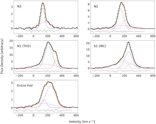
Br α spectrum of identified sources (along with the entire imaged region) and best-fitting Gaussian models of the line profiles. Spectra (the black line) were extracted by summing all pixels within apertures (Fig. 3) along the spatial dimensions of the Br α cube. Intensities in all panels are scaled by a common normalization factor. With clear asymmetries and structure in the line profiles, none of the sources can be modelled well with a single-component Gaussian profile. Models with two or more Gaussian components provide much better fits to the data, as shown in each panel by the best-fitting model (the solid orange line), its individual fit components (the dashed lines), and the fit residuals (the grey curve). All sources exhibit a ‘primary’ bright peak component and a ‘broad’ component that may appear as a blue wing extending out to large negative velocity away from line centre with weak, if any, corresponding emission on the red side. A third, ‘narrow’ and red component is additionally required to model N2, N1, and S1.
More realistic models of the Br α line comprising two or three Gaussian components rather than one, selected using the Bayesian information criterion, are shown in Fig. 4. Parameters for each component of these models are reported in Table 2. Generally, the profile is characterized by a broad component (FWHMbroad ∼ 300–350 |$\rm km\, s^{-1}$|) at the base of a primary emission peak (FWHMprimary ∼ 90–130 |$\rm km\, s^{-1}$|). The broad emission has the highest intensity and largest line width for sources N1 and S1 at the radio and IRCs, respectively, where it appears almost exclusively on the blue side of the line. A blue wing is similarly exhibited by the Br γ line in this region (Günthardt et al. 2019) and by H α tracing more extended gas in regions of low extinction (Westmoquette et al. 2011). Blue wings are common in nebular lines from starburst regions, and suggest that extinction may be blocking the red wing from view, so these line widths are lower limits. In addition to the broad and primary components, the line shows a third, narrow (FWHMnarrow ∼ 60 |$\rm km\, s^{-1}$|) component strongest near N1 with a peak reaching an offset of Δvn,p ≡ vnarrow − vprimary ≃ +100 |$\rm km\, s^{-1}$| from the primary component. The Br γ line shows evidence of this narrow feature, however, it is not identified as a distinct peak (Günthardt et al. 2019).
| Source | 0h47m (ICRS)(1) | −25°17′ (ICRS) | vprimary (|$\rm km\, s^{-1}$|)(2) | FWHMprimary (|$\rm km\, s^{-1}$|)(3) | |$F_{\rm primary}/F_{\rm tot}^{(4)}$| |
|---|---|---|---|---|---|
| N3 | 33|${^{\rm s}_{.}}$|83 | 12 arcsec | 131 ± 2 | 62 ± 7 | 0.53 |
| N2 | 33|${^{\rm s}_{.}}$|52 | 14 arcsec | 148 ± 14 | 89 ± 14 | 0.51 |
| N1 (radio core) | 33|${^{\rm s}_{.}}$|16 | 17 arcsec | 214 ± 1 | 133 ± 4 | 0.59 |
| S1 (IRC) | 33|${^{\rm s}_{.}}$|01 | 19 arcsec | 257 ± 1 | 123 ± 4 | 0.49 |
| vbroad (|$\rm km\, s^{-1}$|)(5) | FWHMbroad (|$\rm km\, s^{-1}$|)(6) | |$F_{\rm broad}/F_{\rm tot}^{(7)}$| | vnarrow (|$\rm km\, s^{-1}$|)(8) | FWHMnarrow (|$\rm km\, s^{-1}$|)(9) | |$F_{\rm narrow}/F_{\rm tot}^{(10)}$| |
| 165 ± 13 | 170 ± 23 | 0.47 | ... | ... | ... |
| 168 ± 11 | 313 ± 35 | 0.30 | 201 ± 14 | 69 ± 14 | 0.18 |
| 168 ± 6 | 347 ± 14 | 0.30 | 316 ± 1 | 63 ± 2 | 0.11 |
| 182 ± 5 | 301 ± 7 | 0.47 | 257 ± 1 | 36 ± 4 | 0.04 |
Notes.(1) Source centroid coordinates have a 1σ uncertainty of ∼1 arcsec.
(2), (5), (8) Centroid velocity (heliocentric) for each Gaussian component of the best-fitting two- or three-component model. The components are labelled as ‘primary’, ‘broad’, and ‘narrow’ (the narrow component can be fit to all but source N3).
(3), (6), (9) FWHM of each Gaussian component in the best-fitting model.
(4), (7), (10) Fraction of total line flux in each component of the best-fitting model (ratio of each component flux that to the summed flux of all components).
| Source | 0h47m (ICRS)(1) | −25°17′ (ICRS) | vprimary (|$\rm km\, s^{-1}$|)(2) | FWHMprimary (|$\rm km\, s^{-1}$|)(3) | |$F_{\rm primary}/F_{\rm tot}^{(4)}$| |
|---|---|---|---|---|---|
| N3 | 33|${^{\rm s}_{.}}$|83 | 12 arcsec | 131 ± 2 | 62 ± 7 | 0.53 |
| N2 | 33|${^{\rm s}_{.}}$|52 | 14 arcsec | 148 ± 14 | 89 ± 14 | 0.51 |
| N1 (radio core) | 33|${^{\rm s}_{.}}$|16 | 17 arcsec | 214 ± 1 | 133 ± 4 | 0.59 |
| S1 (IRC) | 33|${^{\rm s}_{.}}$|01 | 19 arcsec | 257 ± 1 | 123 ± 4 | 0.49 |
| vbroad (|$\rm km\, s^{-1}$|)(5) | FWHMbroad (|$\rm km\, s^{-1}$|)(6) | |$F_{\rm broad}/F_{\rm tot}^{(7)}$| | vnarrow (|$\rm km\, s^{-1}$|)(8) | FWHMnarrow (|$\rm km\, s^{-1}$|)(9) | |$F_{\rm narrow}/F_{\rm tot}^{(10)}$| |
| 165 ± 13 | 170 ± 23 | 0.47 | ... | ... | ... |
| 168 ± 11 | 313 ± 35 | 0.30 | 201 ± 14 | 69 ± 14 | 0.18 |
| 168 ± 6 | 347 ± 14 | 0.30 | 316 ± 1 | 63 ± 2 | 0.11 |
| 182 ± 5 | 301 ± 7 | 0.47 | 257 ± 1 | 36 ± 4 | 0.04 |
Notes.(1) Source centroid coordinates have a 1σ uncertainty of ∼1 arcsec.
(2), (5), (8) Centroid velocity (heliocentric) for each Gaussian component of the best-fitting two- or three-component model. The components are labelled as ‘primary’, ‘broad’, and ‘narrow’ (the narrow component can be fit to all but source N3).
(3), (6), (9) FWHM of each Gaussian component in the best-fitting model.
(4), (7), (10) Fraction of total line flux in each component of the best-fitting model (ratio of each component flux that to the summed flux of all components).
While insightful, the average line profiles (Fig. 4) blend together systematic motions within the ∼2 arcsec apertures used for extraction. Fig. 5 shows the line profile mapped across the central region. This map reveals a major axis velocity shift consistent with the change in line centroid between the sources, with velocity increasing (redshifted) from NE to SW. The picture is most complicated near N1, where the narrow third component is strongest. Interestingly, ∼|$0^{\prime \prime }_{.}8$| east of TH2, the narrow red component reaches a peak intensity that is ∼1.4 × higher than that of the the primary component at that location. This narrow red feature could be a kinematically distinct source or a portion of a larger gas flow. We note that the irregular line profile near TH2 suggests the possibility of >3 components that would require higher resolution to distinguish and characterize.
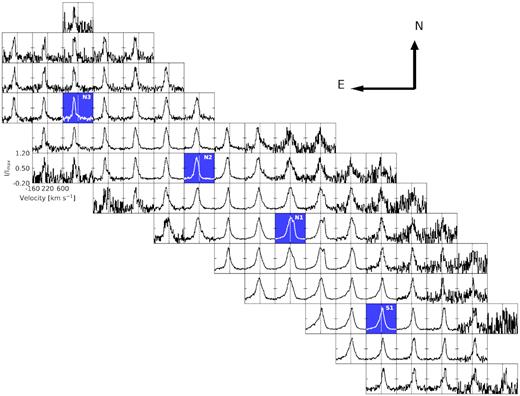
Map of Br α line profile across the NIRSPEC FoV. Each panel gives the summed spectrum within a |$1^{\prime \prime }_{.}2$| × |$1^{\prime \prime }_{.}2$| box centred at that location, and each of these spectra are individually normalized so that variation of the line shape across the region is clear (line peak intensities should not be compared between panels). The blue-highlighted panels show the location of Br α sources. The velocity axis is identical for all spectra, with a vertical line marking the heliocentric systemic velocity vsys = 220 |$\rm km\, s^{-1}$|. Kinematic patterns are clear, in particular: an increase in strength of the broad blue component towards the SE, a double-peaked line structure just east of TH2, and a bulk shift in the line peak velocity centroid to higher velocity (redshift) from NE to SW, along the major axis.
The spectrum map (Fig. 5) also shows that the broad blue wing increases in strength to the south and east of the peak positions in both N1 and S1, with a peak just east of S1, where the feature contributes ∼50 per cent of the line flux. The velocity centroid of broad emission reaches a minimum of Δvb,p ≡ vbroad − vprimary ≃ −90 |$\rm km\, s^{-1}$| at a distance of 1–1.5 arcsec around the eastern side of the IRC, corresponding to the panels immediately to the left of S1 in Fig. 5. Moving NE away from S1, the offset shifts positively, reaching Δvb,p ∼ 0 |$\rm km\, s^{-1}$| in the region north of N1 and west of N2 (in Fig. 5, panels above N1 and to the right of N2). Further NE, the broad component becomes a red wing with Δvb,p ≳ 0 |$\rm km\, s^{-1}$| near N2 and N3 (any panels to the left of N2 in Fig. 5). This change in vb,p is due to the major-axis shift in the primary component, while the broad component centroid remains constant to within ≲20 |$\rm km\, s^{-1}$|. None the less, the broad component shows a clear blueshift to the SE of N1 and S1, explaining the −90 |$\rm km\, s^{-1}$| offset near the IRC. Heavy extinction near the IRC and radio core can explain the much of the blue–red asymmetry of the broad feature; the observed blue wing may not reflect the full kinematic structure.
3.2 Nuclear velocity structure
The NIRSPEC cube (Fig. 2) allows us to probe the detailed ionized gas kinematics using the standard methods of spectral cube analysis. First and second moment maps, representing the intensity-weighted line-of-sight velocity field and dispersion, respectively, were generated from the Br α cube using pixels at >6σrms to identify distinct patterns in the velocity structure (Fig. 6).
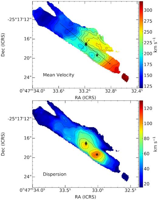
Velocity field of the nuclear region in NGC 253. The upper and lower panels show the intensity-weighted mean velocity (first moment) and dispersion (second moment, equivalent to the line width σv), respectively. Both maps were generated from the NIRSPEC cube using pixels detected at >6σ. Contours mark intervals of 12 and 10 |$\rm km\, s^{-1}$| in the upper and lower panels, respectively. As in other figures, the star marks the IRC and the diamond marks the radio peak TH2. The dashed arrows mark pseudo-slits used to generate major- and minor-axis PV images.
3.2.1 Major-axis velocity gradient
The velocity field in Fig. 6 is complex, comprising several distinct kinematic structures rather than a single-ordered pattern. The simplest of these structures is apparent as the velocity contours at the NE and SW edges of the field (away from TH2 and IRC). Perpendicular to the major axis, these contours indicate a positive gradient from NE to SW across the central ∼12 arcsec≃200 pc (projected). This signal is washed out near N1 and S1, where other kinematic structures clearly dominate the velocity field.
To further probe the rotation curve, we generated a Position–velocity (PV) image using a pseudo-slit centred on TH2 oriented parallel to the major axis, at PA = 51°. The resulting major-axis PV diagram (Fig. 7, left) more clearly exhibits solid-body rotational pattern across the regions of more complex kinematic structure. The major-axis rotation curve, or 1D velocity profile, is derived from best-fitting models of multicomponent Gaussian profiles to the spectrum in each column of the PV image. We take the primary fit component (as opposed to the broad wing or red narrow component) to generate the curve shown in the right-hand panel of Fig. 7. The best-fitting velocity gradient is 10 |$\rm km\, s^{-1}$| arcsec−1. A major-axis gradient of this magnitude has been well measured with many gas tracers, including RRLs (Anantharamaiah & Goss 1996; Rodríguez-Rico et al. 2006), Br γ, H2, and CO (Engelbracht et al. 1998; Günthardt et al. 2015; Leroy et al. 2015).
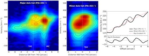
Position–velocity images along the major (left-hand panel) and minor axes (middle panel), along with velocity profiles extracted from these PV images (right-hand panel). The pseudo-slits used to generate the PV images, shown in Fig. 6 as the dashed black arrows, are centred on the radio peak TH2, which corresponds to x = 0 in all panels. The IRC/radio source TH7 is at a position x ≃ |$3^{\prime \prime }_{.}3$| in the major-axis diagram.
From Fig. 7, it is clear that the major-axis velocity profile of the primary Br α component is more complex than a simple gradient from solid-body rotation. The residuals show a sinusoidal structure seemingly associated with sources; the largest residual peaks slightly precede positions of N1/TH2 and S1/IRC. Best-fitting sinusoidal curves indicate residual amplitudes of 17 and 12 |$\rm km\, s^{-1}$| for N1 and S1, respectively. For both sources, residual peaks are offset by about |$0^{\prime \prime }_{.}5$| NE of the emission peaks (TH2 and IRC). This results in velocity gradients across the radio and IRCs of approximately −20 and −15 |$\rm km\, s^{-1}$| arcsec−1, flipped with respect to the underlying 10 |$\rm km\, s^{-1}$| arcsec−1 gradient. Similar major-axis velocity residuals were reported in Anantharamaiah & Goss (1996) and Günthardt et al. (2015).
The kinematic centre, systemic velocity, and PA of the nuclear disc rotation are estimated using BBarolo (Di Teodoro & Fraternali 2015) to fit a tilted-ring model to the velocity field, with inclination fixed to i = 78.5°. The best-fitting model has centre (αicrs, δicrs) = (00h47m33|${^{\rm s}_{.}}$|09, −25°17′|$17^{\prime \prime }_{.}8$|) with an uncertainty of σ ≃ 1 arcsec, vsys = 226 ± 11 |$\rm km\, s^{-1}$|, and PA ϕd = 51 ± 6°. The disc PA and systemic velocity are in close agreement with the literature (e.g. Anantharamaiah & Goss 1996; Das et al. 2001). The dynamical centre is within ≲|$0^{\prime \prime }_{.}7$| of previous determinations (Anantharamaiah & Goss 1996; Müller-Sánchez et al. 2010; Rosenberg et al. 2013), and is ≃|$1^{\prime \prime }_{.}5$| closer to TH2 than to the IRC. We note that tilted-ring modelling is limited in its ability to explain the nuclear kinematics, due to the significant non-rotational structure present in the velocity field.
3.2.2 Substructure of the radio core and source N1
The most prominent pattern in the velocity field (Fig. 6) comprises the S-shaped velocity contours at source N1, centred close to the radio peak TH2. This kinematic substructure has a characteristic size of ∼2–3 arcsec≃30–50 pc, based on the contours. Unlike the underlying solid-body rotation pattern, the contours of N1 are nearly parallel to the major axis, implying a velocity gradient of ∼+50 |$\rm km\, s^{-1}$| arcsec−1 from SE to NW along the minor axis. Again, the Br α velocity structure is consistent with prior measurements of RRLs: Anantharamaiah & Goss (1996) find a minor-axis gradient of ∼20–30 |$\rm km\, s^{-1}$| arcsec−1 for H92 α; Rodríguez-Rico et al. (2006) similarly find a 25 |$\rm km\, s^{-1}$| arcsec−1 for H92 α but infer a larger value of 42 |$\rm km\, s^{-1}$| arcsec−1 for H53 α, closer to our estimate. The K-band velocity fields presented in Rosenberg et al. (2013) are the closest comparison to our Br α field; their H2 field resolves the same three substructures identified in our map. Interestingly, their stellar velocity field also shows the S-shaped velocity contours, suggesting a common dynamical origin for the gas and stars in the radio core.
In the major-axis PV image (Fig. 7, left), source N1 is resolved into two bright components connected by fainter emission surrounding a central ‘hole’. The bright components here were identified as the primary and narrow red component in the Br α line profiles (Fig. 4). The PV ‘hole’ is centred at a position ≃0.7–0.8 arcsec to the SW of TH2 and heliocentric velocity v ≃ 230 |$\rm km\, s^{-1}$|, with an extent of Δx ∼ 2 arcsec along the position axis and Δv ∼100 |$\rm km\, s^{-1}$| along the velocity axis. This structure is likely related to the local maximum in velocity dispersion near TH2 (Fig. 6), which reaches σv ≃ 90 |$\rm km\, s^{-1}$|. The major-axis PV morphology suggests that the radio core can be characterized by a single dynamical structure.
A PV image was extracted along the minor-axis (PA = 141°) from a pseudo-slit centred on TH2 (Fig. 7, middle). The emission along this axis is resolved into the primary bright core following a steep velocity gradient, the extended blue tail on its SE side, and the red component in a bright clump on the NW side. The minor-axis velocity curve of the primary component, extracted in the same way as the major-axis velocity curve, is linear within [−|$0^{\prime \prime }_{.}6$|, |$0^{\prime \prime }_{.}6$|] of TH2 (Fig. 7) with a best-fitting gradient of +41 |$\rm km\, s^{-1}$| arcsec−1 from SE to NW. This gradient, however, spans a distance only slightly larger than the spatial resolution of our data. The true velocity curve for for R ≲ 5–10 pc might have an even steeper gradient or significantly depart from a linear profile, but such structures would be smeared out in our NIRSPEC cube. Indeed, Rodríguez-Rico et al. (2006) measure a minor-axis gradient of 110 |$\rm km\, s^{-1}$| arcsec−1 in a high-resolution map (∼|$0^{\prime \prime }_{.}3$| beam) of H92 α.
3.2.3 Substructure of the IRC and source S1
A third, distinct kinematic substructure is exhibited by the velocity field of S1 as an arc of blueshifted emission around the east side of the of the IRC (Fig. 6, top). The S1 blue flow corresponds to the maximum velocity dispersion in the NIRSPEC FoV, reaching |$\sigma _{{\rm Br}\, \alpha } \simeq 110$| |$\rm km\, s^{-1}$| (Fig. 6, bottom). The gas within the blue knot reaches a maximum LoS velocity shift of Δv = −20 |$\rm km\, s^{-1}$| at a distance of about |$0^{\prime \prime }_{.}8$| from the IRC peak. RRL velocity fields show a ‘kink’ in the contours near the S1 region likely related to this feature (Anantharamaiah & Goss 1996; Rodríguez-Rico et al. 2006). The blue wing in Figs 4 and 5 contributes the most to the Br α line profile at the location of the blue flow, suggesting that these features are physically related.
The major-axis PV diagram (Fig. 7, left) detects S1 as a single brightest emission peak with broad, extended curved wings on both the red and blue sides of the line. The central peak shows a velocity gradient with opposite orientation to the smooth major-axis gradient, which is exhibited in Fig. 7, right, as a residual from the linear fit at x ≃ 3 arcsec, corresponding to a −15 |$\rm km\, s^{-1}$| arcsec−1 gradient across the IRC. Günthardt et al. (2015) find a similar negative gradient of about −20 |$\rm km\, s^{-1}$| arcsec−1 for the ∼1.5 arcsec across the IRC in their H2 rotation curve. Unfortunately, the NIRSPEC slit coverage does not extend more than ∼1–1.5 arcsec to the SE side of the IRC, such that we cannot determine if the blue flow in Fig. 6 is part of a larger kinematic substructure.
4 DISCUSSION
Kinematic structures in the Br α velocity field (Figs 6 and 7) are linked primarily to the brightest sources sources in the region: N1 at the radio core and S1 at the IRC. These gas motions reflect the fundamental, complex mechanisms of secular galaxy evolution and the mass evolution of the centres of galaxies.
4.1 Gaseous bar structure near the radio nucleus
The strongest kinematic substructure, associated with N1, is distinguished by S-shaped velocity contours. S-shaped contours are characteristic of motion in a barred potential (e.g. Athanassoula 1984; Athanassoula & Bureau 1999; Kormendy & Kennicutt 2004).
Contours in the Br α velocity field (Fig. 6) are oriented at PA ≃ 45°, close to the major-axis disc (PA = 51°) and aligned with the nuclear thermal radio continuum knots (Turner & Ho 1983, 1985; Ulvestad & Antonucci 1997). This is exactly the orientation of sky-projected inner x2 orbits in the barred potential model from Das et al. (2001), which was used to explain the H92 α (Anantharamaiah & Goss 1996) and CO velocity fields. In the Das et al. (2001) model, the x1 orbits, along the bar’s major axis, form the larger NIR bar structure observed at PA = 70° (Scoville et al. 1985; Arnaboldi et al. 1995; Peng et al. 1996; Iodice et al. 2014). We suggest that gas within the inner ring of x2 orbits (along the NIR bar’s minor axis) comprises a secondary nuclear bar that dominates ionized gas velocity structure in the radio core.
The candidate nuclear bar in NGC 253 is small. Its length Lbar ≃ 5 arcsec ∼ 85 pc (Fig. 6) is only ∼1 per cent the size of the primary galactic bar in NGC 253, which has length ∼7 kpc (e.g. Scoville et al. 1985; Arnaboldi et al. 1995; Das et al. 2001). The Br α velocity profile indicates that is it rapidly rotating. The angular speed of the solid-body disc rotation is constant at Ω ≃ 590 |$\rm km\, s^{-1}$| kpc−1. However, the gradient is steeper across the bar region, roughly −20 |$\rm km\, s^{-1}$| arcsec−1 along the major axis within R ≲ |$1^{\prime \prime }_{.}0$|, corresponding to an angular speed of Ω ∼ 1200 |$\rm km\, s^{-1}$| kpc−1 (Fig. 7). In reality, the secondary bar rotation speed is somewhere in between, Ωs,bar ∼ 600–1200 |$\rm km\, s^{-1}$| kpc−1. At R ∼ 50 pc, the angular speed is ≳10 × faster than the primary bar’s pattern speed of Ωp,bar ∼ 50 |$\rm km\, s^{-1}$| kpc−1. The result, albeit uncertain due to inevitable contributions of star cluster feedback to the velocity field, may be compared with the few existing measurements of inner bar rotation speed. Velocity maps produced from H α observations generally suggest secondary nuclear bars rotate ≳3 × faster than primary bars, reaching Ω ∼ 100–500 |$\rm km\, s^{-1}$| kpc−1 (e.g. Font et al. 2014). Although this is slow compared to the rotation implied by Br α for NGC 253, the discrepancy might arise because the H α emission traces an unobscured, extended gas component, while Br α emission can originate in obscured gas within a dusty bar.
The Br α velocity structure presented here is perhaps the strongest evidence yet for a nuclear bar in NGC 253. While tentative evidence for arcing contours has been found in RRL velocity fields, beam smearing and insufficient velocity resolution wash out the characteristic S-shaped bending (e.g. Anantharamaiah & Goss 1996; Das et al. 2001; Rodríguez-Rico et al. 2006). Using K-band observations, Rosenberg et al. (2013) is the only other investigation to unambiguously resolve this structure, to the best of our knowledge. Interestingly, the S-shaped pattern at the radio core was found not only in their H2 velocity field, but also in their stellar velocity field, strongly suggesting a gravitational origin. Conversely, the IRC’s blue flow identified in our Br α velocity field is marginally seen in the H2 field but has no counterpart in the stellar field, indicating gas dynamics shaped by star formation. We conclude that the radio core comprises gas and forming massive star clusters, orbiting within the strong gravitational potential of a ≲100 pc long nuclear bar. Constraining the properties of the bar, such as pattern speed and morphology, will require further observational study.
4.2 The radio core as the galactic centre
The build-up of massive galactic bulges is largely driven by the formation and feedback of SMBHs, which are ubiquitous in massive galaxies. The symmetry of velocity contours near N1 favours the radio core, close to the brightest radio source TH2, as the location of the galaxy’s kinematic centre, rather than the IRC. The nature of TH2 is elusive. Its high brightness temperature (Turner & Ho 1985) and lack of associated mid-infrared continuum emission indicates a non-thermal emission mechanism, strongly disfavouring an H ii region powered by SSCs as its origin. Rather, the two leading explanations of TH2 are an unusually bright supernova remnant (SNR), or an AGN (Turner & Ho 1985; Ulvestad & Antonucci 1997; Mohan, Anantharamaiah & Goss 2002). TH2 would be an unusually bright SNR, ∼100 times brighter than the Galaxy’s brightest SNR, Cas A. Although there is no X-ray or IR counterpart source associated with TH2 (Fernández-Ontiveros et al. 2009; Müller-Sánchez et al. 2010), the presence of high-J CO, HCN, and dust emission suggests very high extinctions (Bolatto et al. 2013; Meier et al. 2015; Leroy et al. 2018). If TH2 is indeed a weak AGN, it would be a valuable nearby example of the starburst–AGN interaction.
The Br α velocity profile across TH2 yields mass estimates for a potential central SMBH in the radio core (Fig. 7). The minor-axis velocity gradient, roughly 50 |$\rm km\, s^{-1}$| over |$1^{\prime \prime }_{.}5$|, suggests |$M_{\mathrm{dyn}}^{\mathrm{TH2}}\sim 1.4 \times 10^7$| |$\rm M_\odot$|. A similar mass of |$M_{\mathrm{dyn}}^{\mathrm{TH2}}\sim 7\times 10^6$| |$\rm M_\odot$|, based on a ∼110 |$\rm km\, s^{-1}$| arcsec−1 gradient, is derived from the |$0^{\prime \prime }_{.}3$|-beam H92 α map in Rodríguez-Rico et al. (2006). Given the measured central stellar velocity dispersion of NGC 253 (σ = 109 |$\rm km\, s^{-1}$|; Oliva et al. 1995), the M–σ relation (Combes et al. 2019) predicts an SMBH of mass Mbh ∼ 2 × 10⁷ |$\rm M_\odot$|, consistent with the estimate from Br α. The predicted sphere of influence has radius rh ∼ GMbh/σ2 ∼ 8 pc (Merritt 2004). The true velocity profile within the black hole’s sphere of influence could be characterized by a significantly steeper gradient than is measured after being smeared out by the point spread function of our observations. Extremely high extinction (AV ≳ 50) in the centre of NGC 253 (e.g. Leroy et al. 2018), should also significantly affect measurements of the velocity field of IR emission lines and thus estimates of dynamical mass.
High-resolution observations of gas in the centres of Seyfert galaxies suggest nuclear bars may be intimately tied to AGN phenomena, closely linked to the feeding and growth of SMBHs (e.g. Onishi et al. 2015; Barth et al. 2016; Davis et al. 2017, 2018). Given the bar-like kinematic substructure from our Br α measurements, the radio core of NGC 253 near TH2 is an excellent target for high-resolution IR-radio gas spectroscopy.
4.3 Starburst feedback: outflow from the IRC?
The starburst region of NGC 253 is driving a large-scale galactic wind, with an ionized outflow extending to ∼10 kpc (e.g. Strickland et al. 2002; Weaver et al. 2002; Westmoquette et al. 2011; Günthardt et al. 2019) along with molecular outflow from the central ≲1kpc (e.g. Sakamoto et al. 2006; Bolatto et al. 2013; Walter et al. 2017). The galactic wind should be powered by feedback from SSCs identified in the central starburst region (e.g. Turner & Ho 1985; Watson et al. 1996; Ulvestad & Antonucci 1997; Engelbracht et al. 1998; Forbes et al. 2000; Fernández-Ontiveros et al. 2009; Leroy et al. 2018). Characterization of outflow sources in NGC 253 is key for understanding the link between feedback from its starburst and its galactic wind.
Source S1 at the IRC exhibits the best evidence for outflow from its line profile and kinematic substructure. Assuming a mass of 106 |$\rm M_\odot$| (Leroy et al. 2018), the predicted escape velocity from the IRC is vesc(R = 20 pc) ∼ 20 |$\rm km\, s^{-1}$|. This is significantly smaller than the Br α line width of S1, σv ∼50, 130 |$\rm km\, s^{-1}$| for the primary and broad Br α components, respectively (Fig. 4). A maximum outflow velocity can be estimated with the velocity offset between the broad and primary components and the broad-component line width: vmax = Δvb,p − FWHMbroad/2 (e.g. Veilleux, Cecil & Bland-Hawthorn 2005; Arribas et al. 2014; Wood et al. 2015). Using average values for S1, Δvb,p ≃ −75 |$\rm km\, s^{-1}$| and FWHMbroad ≃ 300 |$\rm km\, s^{-1}$|, yields vmax ∼ −225 |$\rm km\, s^{-1}$|, consistent with the Br γ outflow (Günthardt et al. 2019).
The potential outflow from the IRC is identified as a blueshifted substructure in the Br α velocity field distinct from the nuclear bar pattern (Fig. 6), and as a negative velocity gradient and with the curving red and blue wings in the major-axis PV image (Fig. 7). These structures suggest deprojected outflow speeds of ≳100 |$\rm km\, s^{-1}$|, consistent with estimates from the line profile. We conclude that the Br α outflow from the IRC forms the base of the ∼100−300 |$\rm km\, s^{-1}$| H α outflow (Westmoquette et al. 2011). Feedback from ∼6 to ∼8 Myr old SSC in the IRC appears presently capable of powering the kpc-scale galactic wind.
Like the Br α emission from S1, the emission from N1 has a broad blue component with line width exceeding the local escape velocity, indicating star formation feedback. However, the nuclear bar clearly dominates the velocity structure in the radio core. Compared with the IRC, the radio core exhibits a significantly larger Brackett line equivalent width, |$W({\rm Br}\, \alpha)\sim 250$| Å (Section 3.1), and extinction (AV ∼ 20−4000; Günthardt et al. 2015; Leroy et al. 2018). This suggests a younger stellar population within the radio core formed in a more recent starburst episode. Feedback might be correspondingly weaker in this region if clusters have not yet evolved WR winds and SNe capable of driving significant mass-loss. Alternatively, feedback might be suppressed as newly formed clusters separate from their natal gas within the bar potential due to tidal interactions. NGC 253 demonstrates the complex interplay between nuclear gravitational structure and star formation shaping the evolution of its central bulge.
5 SUMMARY
Using NIRSPEC, we have mapped the Br α line in the core of NGC 253, the site of a forming galactic centre, and an intense starburst that is powering a galactic wind on much larger scales. The constructed Br α cube, with 1 arcsec and 12 |$\rm km\, s^{-1}$| resolutions, reveals four sources associated with complex gas motions influenced by nuclear galactic structure along with feedback from forming massive clusters. The two brightest sources, which we identify as N1 and S1, are associated with the bright radio and IRCs, respectively. Our main findings are as follows:
An underlying gradient of 10 |$\rm km\, s^{-1}$| arcsec−1 across >10 arcsec along the major axis is identified as the solid-body rotation curve of the inner disc. Residuals of a linear fit appear sinusoidal, with peaks of amplitude ∼15 |$\rm km\, s^{-1}$| offset roughly |$0^{\prime \prime }_{.}6$| ≃ 10 projected-pc to the NE of each Br α sources. The residuals reflect non-circular motions; likely tracing structure of an inner nuclear bar/nuclear spiral.
S-shaped contours in the velocity field near N1 provide strong evidence for a nuclear gaseous bar centred on the radio core oriented at PA ≃ 45°, aligned with predicted inner x2 orbits of the larger galactic bar (Das et al. 2001; Paglione et al. 2004). The inner bar has radius R ∼ 40−50 pc and is rotating rapidly, with Ω ≳ 600 km s−1. Intense star formation indicated by candidates SSCs and SNRs suggest that the nuclear bar can induce inflow into the galactic centre and fuel star formation.
The galactic centre, expected to host an SMBH, is near the radio peak TH2 in the radio nucleus rather than in the IRC. Based on the minor-axis gradient of 41 |$\rm km\, s^{-1}$| arcsec−1 across TH2, we derive a mass of ∼107 |$\rm M_\odot$| across |$1^{\prime \prime }_{.}5$| ≃ 25 pc, which can be compared with M ∼ 7 × 10⁶ |$\rm M_\odot$| derived previously from subarcsecond resolution RRL observations (Rodríguez-Rico et al. 2006). The sphere of influence of this black hole is ≲8 pc in radius. The values are in rough agreement, given the lower spatial resolution of these data. The mass expected from the M–σ relation, M ∼ 107 |$\rm M_\odot$|, is consistent with the measurements.
The kinematics of source S1 indicate outflow driven by the IRC. Broad emission contributes half of the total line flux here, and has a line width greatly exceeding local escape velocities (FWHM ∼ 300–350 |$\rm km\, s^{-1}$|). The velocity field shows the outflow as a blueshifted arc-like substructure at the IRC, distinct from the nuclear bar pattern. The estimated maximum outflow speed is |vmax| ∼ 200−250 |$\rm km\, s^{-1}$|, consistent with the H α outflow (Westmoquette et al. 2011). The results provide a plausible link between feedback from star formation in the IRC and the observed large-scale galactic wind.
With a potential nuclear bar and SMBH, the radio core of NGC 253 is an ideal target for high-resolution IR-radio spectroscopic observations. Such measurements will provide insight into the nature of the non-thermal radio source, the presence and influence of an SMBH, and operation of feedback from individual SSCs in forming the galactic centre.
ACKNOWLEDGEMENTS
The data presented herein were obtained at the W. M. Keck Observatory, which is operated as a scientific partnership among the California Institute of Technology, the University of California, and the National Aeronautics and Space Administration. The Observatory was made possible by the generous financial support of the W. M. Keck Foundation. The authors wish to recognize and acknowledge the very significant cultural role and reverence that the summit of Maunakea has always had within the indigenous Hawaiian community. We are most fortunate to have the opportunity to conduct observations from this mountain. This work was supported in part by National Science Foundation Astronomical Sciences Grant 15155070.
