


Abstract
We present the analysis of six Chandra X-ray high-resolution observations of the black hole low-mass X-ray binary 4U 1630-47 taken during its 2012–2013 outburst. Fe xxvi K α, K β, Fe xxv K α, K β, and Ca xx K α blueshifted absorption lines were identified in the first four observations, which correspond to soft accretion states. The remaining observations, associated to intermediate and possibly hard accretion states, do not show significant absorption features down to equivalent width of 1 eV for both Fe xxvi and Fe xxv. We inferred wind launching radii between 1.2 − 2.0 (1012 cm/n) × 1011 cm and column densities N(H) > 1023 cm−2. In the first four observations, we found that thermal pressure is likely to be the dominant launching mechanism for the wind, although such conclusions depend on the assumed density. We used the spectral energy distributions obtained from our continuum modelling to compute thermal stability curves for all observations using the xstar photoionization code. We found that the absence of lines in the transitional state cannot be attributed to an evolution of the plasma caused by thermal instabilities derived from the change in the continuum spectrum. In contrast, the disappearance of the wind could indicate an acceleration of the flow or that the plasma has been exhausted during the soft state.
1 INTRODUCTION
In the last decade, analysis of black hole low-mass X-ray binaries (BH LMXBs) using X-ray spectra has shown the presence of photoionized plasmas in such systems (see Díaz Trigo & Boirin 2016, and references therein). The plasmas can be found as a bound atmosphere or they can flow outwards with velocity blueshifts well above 1000 km s−1 (Kallman et al. 2009). Although it is not clear which mechanism is responsible for the wind launching, the best candidates include thermal pressure, radiative pressure, and magnetic pressure. Thermal pressure consists of the heating of the gas by the central X-ray source, producing an outflow at large distances from the central object, when the thermal velocity is larger than the local escape velocity (Begelman, McKee & Shields 1983; Woods et al. 1996; Netzer 2006; Higginbottom & Proga 2015; Higginbottom et al. 2017). Radiative pressure can be produced by electrons scattering, at near- or super-Eddington luminosities, or lines (Różańska et al. 2014; Hashizume et al. 2015; Shidatsu, Done & Ueda 2016). However, it has been shown that, for BH LMXBs, radiation pressure cannot launch an outflow due to the low number of soft X-ray and UV lines (Proga & Kallman 2002). Finally, magnetic pressure or magnetocentrifugal forces can produce winds at small radii, although more work needs to be done, from the theoretical point of view, in order to reproduce the observed spectra (Blandford & Payne 1982; Proga 2003; Chakravorty et al. 2016; Li & Begelman 2014).
From the observational point of view, thermal winds have been favoured by a majority of observations (Kubota et al. 2007; Neilsen & Homan 2012; Różańska et al. 2014; Díaz Trigo & Boirin 2016; Allen et al. 2018; Done, Tomaru & Takahashi 2018; Tomaru et al. 2018) although radiation pressure due to electrons (Kotani et al. 2000; Kubota et al. 2007; Neilsen & Lee 2009a; Díaz Trigo et al. 2014; Różańska et al. 2014; Miller et al. 2016b; Shidatsu et al. 2016) and magnetic forces (Miller et al. 2006a, 2008; Luketic et al. 2010; King et al. 2014; Miller et al. 2006a, 2016a; Fukumura et al. 2017; Tetarenko et al. 2018) have also been invoked to explain a handful of cases.
An open issue is the connection between the outflowing winds and the accretion state. During outburst, BH X-ray binaries show a hysteresis pattern in the hardness–intensity diagram that has been associated to transitions through different accretion states (Fender, Belloni & Gallo 2004; Fender & Belloni 2012). Because the winds have been observed in a number of BHs to be stronger in the soft accretion state in which jets are quenched (Miller et al. 2006a,b; Díaz Trigo et al. 2007; Kubota et al. 2007; Ueda, Yamaoka & Remillard 2009; Díaz Trigo et al. 2014), it was proposed that jets and winds were preventing each other from forming (Neilsen & Lee 2009b). However, it has been recently shown that disc winds and jets may co-exist. For example, Homan et al. (2016) found indications that some sources could produce winds and jets in the same accretion state (albeit with non-simultaneous observations) and concluded that if the LMXB luminosity is above a few tens of per cent of the Eddington luminosity, disc winds and jets may co-exist. In the case of the BH LMXB V404 Cygni, an optical wind has been identified simultaneously with a radio jet by Muñoz-Darias et al. (2017). Also, Rahoui, Coriat & Lee (2014) found a broad Paβ absorption feature in the hard state of BH LMXB GX 339–4 using observations taken with the ESO/Very Large Telescope (VLT) that they attributed to a wind. Despite the efforts made to improve our understanding of these phenomena, multiple questions remain, including: What dictates the balance of power and the matter/radiation content of the disc, wind, and jet? Is the disc–jet connection defined by the accretion flow only or does it depend on the compact object? And how do winds affect the accretion process?
The BH LMXB 4U 1630-47 constitutes an excellent laboratory to study the disc–jet connection. It has been identified as a recurrent transient (Jones et al. 1976; Parmar, Angelini & White 1995; Kuulkers et al. 1997; Tomsick et al. 2005) with an inclination of ∼60–75 ° (Kuulkers et al. 1998; Tomsick, Lapshov & Kaaret 1998). Radio emission has been detected at flux levels always < 3 mJy beam−1 and has been identified with the presence of jets in this system (Hjellming et al. 1999; Díaz Trigo et al. 2013; but see Neilsen et al. 2014 for a different interpretation).
Suzaku spectra of this source were analysed by Kubota et al. (2007) who first identified a highly ionized disc wind traced by Fe xxvi and Fe xxv absorption lines during the 2006 outburst. They concluded that thermal and radiative pressure processes can be part of the launching mechanism without discarding completely magnetic processes. Díaz Trigo et al. (2014) analysed XMM-Newton X-ray spectra obtained during the 2011–2013 outburst. They identified Fe xxvi, Fe xxv, Ni xxviii, Ni xxvii, and S xvi absorption lines associated with a disc wind being thermally–radiatively driven during a soft state of the source. They followed the source across the transition from a soft state to a very high state and attributed the disappearance of the wind in a very high state to strong ionization of the wind due to the hardening of the spectrum and the increase of luminosity during that state. Neilsen et al. (2014) analysed Chandra high-resolution spectra obtained in 2012 during the same outburst. They fitted the continuum of the observation taken on January 2012 with a disc blackbody and classified the source as being in a soft accretion state, with the presence of absorption lines due to Fe xxvi, Fe xxv, Ca xx, Ni xxviii, and Ni xxvii. In contrast, they found that the continuum of the observation taken in June 2012 shows an additional power-law component and no absorption lines.
With the aim of studying further the connection of the wind, jet, and accretion state across state transitions, we obtained two simultaneous Chandra and VLA observations during a soft-to-hard state transition. For comparison, we also used four Chandra observations from an earlier time in the outburst that show significant line absorption (Neilsen et al. 2014). The outline of this paper is as follows. In Section 2, we describe data selection and reduction. The continuum modelling and the fit of the absorption lines identified are described in Sections 3.1 and 3.2, respectively. Results obtained by using photoionization models are reviewed in Section 3.3. An analysis of the thermal stability curves derived for all observations is included in Section 4. In Section 5, we discuss the possible launching mechanisms present in this system and Section 6 summarizes the main results of our analysis. We assume a value of 10 kpc throughout this paper, as previous authors (Abe et al. 2005; Tomsick et al. 2005; Díaz Trigo et al. 2014) but note that Kalemci, Maccarone & Tomsick (2018) have recently reported two potential distances of 4.7 ± 0.3 kpc and 11.5 ± 0.3 kpc to the source based on an analysis of the dust scattering halo around the source.
2 OBSERVATIONS AND DATA REDUCTION
2.1 X-ray observations
Table 1 shows the specifications, including IDs, dates, exposure times, and count rates, of the LMXB 4U 1630-47 Chandra observations analysed in this paper. All observations were obtained using the Advanced CCD Imaging Spectrometer (ACIS) in combination with the High-Energy Grating (HEG) of the High-Energy Transmission Grating Spectrometer (HETGS) instrument. For each observation, we combined both ± 1 HEG orders. The 1.5–10 keV Chandra count rates are included. The observations were reduced following the standard Chandra Interactive Analysis of Observations (CIAO, version 4.9) threads.1 The spectral fitting was performed with the xspec software (version 12.9.1p2), χ2 statistics were used and uncertainties are given at 90|${{\ \rm per\ cent}}$| confidence. Given that we are interested in the analysis of absorption features, we prefer to avoid the rebinning of the data due to the loss of information inherent to such a procedure. Instead, we prefer to use the Churazov et al. (1996) weighting method which allows the analysis of low-count spectra by assigning weights to each channel that correspond to the average counts in surrounding channels. In this way, an almost unbiased accurate estimation of parameters is not only guaranteed but also a goodness-of-fit criterion is provided (contrary to, for example, the Cash (1979) statistic). It is important to note that the smoothing of the data is performed only to calculate the weights, while the fitting procedure is applied to the original spectrum. This weighting method has been used in previous analyses of high-resolution X-ray spectra (Tofflemire et al. 2013; Joachimi et al. 2016; Miller et al. 2016a; Gatuzz & Churazov 2018; Medvedev et al. 2018). Finally, the abundances are given relative to Grevesse & Sauval (1998).
Chandra high-energy grating observations of 4U 1630-47.
| Label | ObsID | Date | MJD | Exposure | Count-rate (cts/s) |
|---|---|---|---|---|---|
| Start-time | (ks) | (1.5–10 keV) | |||
| Obs1 | 13714 | 17 Jan 2012 | 55943.2 | 28.9 | 14.8 |
| Obs2 | 13715 | 20 Jan 2012 | 55943.1 | 29.2 | 14.4 |
| Obs3 | 13716 | 26 Jan 2012 | 55943.1 | 29.2 | 13.7 |
| Obs4 | 13717 | 30 Jan 2012 | 55956.3 | 29.4 | 15.6 |
| Obs5 | 14441 | 03 Jun 2012 | 56081.9 | 19.0 | 20.8 |
| Obs6 | 15511 | 25 Apr 2013 | 56407.2 | 49.4 | 9.8 |
| Obs7 | 15524 | 27 May 2013 | 56439.7 | 48.9 | 0.6 |
2.1.1 X-ray light curves
Fig. 1 shows the daily average light curves obtained during the 4U 1630-47 outburst with the Monitor of All-sky X-ray Image (MAXI/ASM) in the 2–20 keV and 10–20 keV energy ranges and the Neil Gehrels Swift Observatory with the Burst Alert Telescope (Swift/BAT in the 15–50 keV band (bottom panel). In the case of Swift/BAT data, negative values, although without a physical meaning, are obtained from Poisson fluctuations of low-significance bins due to the background subtraction method. Those values are not included in the plot. Fig. 2 shows the hardness–intensity diagram of the source using the MAXI/ASM daily average light curves, and where the hardness ratio is defined as the ratio between the observed fluxes in the 10–20 keV and the 2–4 keV bands. From the diagram, it is clear that Obs 6 is located in a similar region as Obs 1–4 while Obs 5 and 7 lie at a harder region of the diagram. In this sense, we use Obs 1–4 to compare with Obs 6–7. Given that Obs 5 does not show lines (Neilsen et al. 2014) and it is yet in a particular state different from Obs 7, we decide to exclude it in the following analysis.
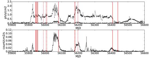
Top panel: MAXI/ASM daily average light curves of 4U 1630-47. The black dashed line corresponds to the 2–20 keV light curve while black solid line corresponds to the 10–20 keV light curve. Bottom panel: Swift/BAT daily average light curve of the LMXB 4U 1630-47 in the 15–50 keV energy range. In both panels, vertical red solid lines indicate the Chandra observation dates while vertical red dashed lines indicate the XMM-Newton observations analysed by Díaz Trigo et al. (2014).
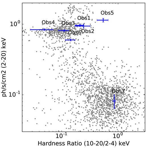
Hardness–intensity diagram of the 4U 1630-47 using MAXI/ASM daily average lightcurves. The positions of the pointed Chandra observations during the outburst are marked by blue crosses.
2.2 Radio observations
During Obs 6 and 7, we made quasi-simultaneous radio observations with the Karl G. Jansky Very Large Array (VLA), under project code SE0242. We observed in two basebands. Each baseband comprised seven continuum spectral windows made up of sixty-four 2-MHz channels. We also centred an eighth spectral window in each baseband on the H94α and H110α recombination lines (rest frequencies of 7.792871 GHz and 4.874157 GHz, respectively, and assuming a systemic radial velocity of −170 km s−1, see Lilley & Palmer 1968), to test for recombination line emission. These spectral line frequencies were observed with narrower channels, of width 50 kHz and 1 MHz, respectively.
The array was in its most compact D configuration for Obs 6 (2013 April 25, 09:00–10:00 UT; MJD 56407.40 ± 0.01), and the low declination of the source meant that the antennas on the northern arm were all shadowed and had to be flagged, leading to a very elongated synthesized beam. We used 3C 286 as a flux density and bandpass calibrator, and the more nearby calibrator J1626 – 2951 to set the complex gains. We achieved a total of 35.3 min of time on the target field. However, the highly elongated synthesized beam and the large amount of diffuse structure in the field meant that the target source was not significantly detected, with a 3σ upper limit of 0.22 mJy beam−1 when stacking the two continuum basebands.
For Obs 7, the VLA observed on 2013 May 28 (06:46–07:46 UT; MJD 56440.31 ± 0.01), using the same frequency setup and calibrator sources. However, the array was in the slightly more extended DnC configuration, providing slightly better N–S resolution. Once again, the diffuse emission in the field coupled with the low elevation of the source, the compact array configuration, and the relatively poor N–S resolution hampered our ability to detect the target. We experimented with both different weighting schemes and minimum uv-distance restrictions on the data, but we were only able to place 3σ upper limits of 0.48 mJy beam−1 at 5.3 GHz and 0.12 mJy beam−1 at 7.2 GHz (where the diffuse emission was fainter and we spatially resolved out a fraction of the more extended structure). In neither observation did we detect any significant recombination line emission (rms noise levels per channel of 0.47 and 0.69 mJy beam−1 for H94α and H110α, respectively).
3 X-RAY SPECTRAL MODELLING
3.1 Continuum modelling
In order to account for different spectral states, we fitted each HEG–ACIS observation in the 1.5–10 keV energy range using multiple phenomenological models. Using xspec nomenclature, the models are:
Model A: tbabs*(powerlaw)
Model B: tbabs*(diskbb)
Model C: tbabs*(powerlaw+diskbb)
Model D: tbabs*simpl(diskbb)
The diskbb component corresponds to an accretion disc consisting of multiple blackbody components (Mitsuda et al. 1984; Makishima et al. 1986). The simpl convolution component is a model of Comptonization in which a fraction of the photons (FracSca parameter) is scattered into a power-law component (Steiner et al. 2009). The tbabs component models the absorption in the local interstellar medium (ISM) as described by Wilms, Allen & McCray (2000). In this way, models A and B consider X-ray spectra dominated by hard and soft components, respectively, while models C and D correspond to a hybrid case. Also, we included several Gaussians in order to model absorption lines identified in the spectra, if present.
The pileup effect, the detection of two or more photons as a single event, can affect the shape and level of the continuum.3 The pileup effect is stronger in the Medium Energy Grating (MEG) than in the HEG instrument. Currently, the only model that can be used to estimate the pileup effect for high-resolution X-ray spectra is simple_gpile2 developed by Hanke et al. (2009) for the isis data analysis package. Using this model, we estimated the highest pileup degree in Obs 1–4, 6–7 to be |$\lt\!\!5{{\ \rm per\ cent}}$| at ≈3.8 keV. We have found that the continuum parameters listed are not affected by the inclusion of the simple_gpile2 model and hence we decide to use the results obtained from the xspec analysis.
Table 2 shows the best-fit parameters obtained for each observation using the models described above. All Gaussians included in the models are listed in Table 3. We consider as valid fits those satisfying (1) χ2/dof < 1.50 and (2) the number of counts predicted by the model in the 15–50 keV energy range agrees with the Swift/BAT daily average measurements (within the uncertainties). Models that do not satisfy both conditions are not included in the analysis hereafter (including the Model A).
4U 1630-47 Chandra HEG best-fit results.
| Component | Parameter | Obs1 | Obs2 | Obs3 | Obs4 | Obs6 | Obs7 |
|---|---|---|---|---|---|---|---|
| Model B: tbabs*(diskbb) | |||||||
| Tbabs | N(H) | 9.15 ± 0.05 | 9.14 ± 0.05 | 9.12 ± 0.05 | 9.23 ± 0.05 | – | – |
| diskbb | kTin | 1.54 ± 0.01 | 1.49 ± 0.01 | 1.52 ± 0.01 | 1.58 ± 0.01 | – | – |
| normdbb | 113 ± 3 | 126 ± 3 | 112 ± 3 | 107 ± 3 | – | – | |
| Statistic | χ2/d.of. | 3056/2810 | 2968/2810 | 2974/2810 | 3084/2810 | – | – |
| red-χ2 | 1.08 | 1.05 | 1.05 | 1.09 | – | – | |
| Count-rate | Model | 6.0 × 10⁻⁵ | 4.9 × 10⁻⁵ | 5.3 × 10⁻⁵ | 7.9 × 10⁻⁵ | – | – |
| (15–50 keV) | Swift/BAT | <5.2 × 10⁻⁴ | <9.5 × 10⁻⁴ | <1.1 × 10⁻³ | <6.4 × 10⁻⁴ | – | – |
| Flux | (0.0136–13.60 keV) | 1.4 × 10⁻⁸ | 1.4 × 10⁻⁸ | 1.3 × 10⁻⁸ | 1.5 × 10⁻⁸ | – | – |
| (1.5–10 keV) | 9.9 × 10⁻⁹ | 9.7 × 10⁻⁹ | 9.3 × 10⁻⁹ | 1.0 × 10⁻⁸ | – | – | |
| (15–50 keV) | 2.3 × 10⁻¹¹ | 2.6 × 10⁻¹⁰ | 1.9 × 10⁻¹¹ | 3.1 × 10⁻¹¹ | – | – | |
| Model C: tbabs*(powerlaw+diskbb) | |||||||
| Tbabs | N(H) | 9.15 ± 0.04 | 9.14 ± 0.04 | 9.12 ± 0.04 | 9.22 ± 0.05 | 9.41 ± 0.27 | 9.10 (fixed) |
| powerlaw | Γ | 2.5 (fixed) | 2.5 (fixed) | 2.5 (fixed) | 2.5 (fixed) | 2.4 ± 0.2 | 2.1 ± 0.3 |
| normpow | <0.08 | <0.07 | <0.07 | <0.08 | |$1.9 _{-0.9}^{+1.5}$| | 0.10 ± 0.05 | |
| diskbb | kTin | 1.54 ± 0.01 | 1.49 ± 0.01 | 1.52 ± 0.01 | 1.58 ± 0.01 | 1.21 ± 0.03 | 0.60 ± 0.03 |
| normdbb | 113 ± 3 | 126 ± 3 | 112 ± 3 | 107 ± 3 | 138 ± 23 | |$284_{-55}^{+75}$| | |
| Statistic | χ2/d.of. | 3056/2810 | 2968/2810 | 2974/2810 | 3084/2810 | 2974/2810 | 2490/2810 |
| red-χ2 | 1.08 | 1.05 | 1.06 | 1.09 | 1.06 | 0.88 | |
| Count-rate | Model | 6.5 × 10⁻⁵ | 5.0 × 10⁻⁵ | 5.4 × 10⁻⁵ | 8.4 × 10⁻⁵ | 2.7 × 10⁻³ | 3.8 × 10⁻⁴ |
| (15–50 keV) | Swift/BAT | <5.2 × 10⁻⁴ | <9.5 × 10⁻⁴ | <1.1 × 10⁻³ | <6.4 × 10⁻⁴ | (2.5 ± 0.2) × 10−3 | (4.1 ± 3.1) × 10−4 |
| Flux | (0.0136–13.60 keV) | 1.4 × 10⁻⁸ | 1.4 × 10⁻⁸ | 1.3 × 10⁻⁸ | 1.4 × 10⁻⁸ | 4.9 × 10⁻⁸ | 2.1 × 10⁻⁹ |
| (1.5–10 keV) | 1.9 × 10⁻⁹ | 9.7 × 10⁻⁹ | 1.0 × 10⁻⁸ | 1.0 × 10⁻⁸ | 7.9 × 10⁻⁹ | 5.4 × 10⁻¹⁰ | |
| (15–50 keV) | 2.3 × 10⁻¹¹ | 2.5 × 10⁻¹⁰ | 1.7 × 10⁻¹¹ | 2.9 × 10⁻¹¹ | 1.0 × 10⁻⁹ | 1.4 × 10⁻¹⁰ | |
| Model D: tbabs*simpl(diskbb) | |||||||
| Tbabs | N(H) | 9.15 ± 0.01 | 9.13 ± 0.02 | 9.12 ± 0.03 | 9.23 ± 0.05 | 9.03 ± 0.09 | 9.10 (fixed) |
| simpl | Γ | <2.00 | <2.00 | <2.00 | <2.00 | 3.7 ± 0.3 | 2.1 ± 0.3 |
| FracSca | <0.01 | <0.01 | <0.01 | <0.01 | |$0.8_{-0.3}^{+0.8}$| | 0.18 ± 0.03 | |
| diskbb | kTin | 1.53 ± 0.01 | 1.49 ± 0.01 | 1.52 ± 0.01 | 1.58 ± 0.01 | 0.90 ± 0.01 | 0.58 ± 0.04 |
| normdbb | |$115_{-4}^{+2E06}$| | |$125_{-3}^{+59}$| | |$112_{-1}^{+105}$| | 108 ± 4 | |$560_{-1}^{+350}$| | |$431^{+181}_{-113}$| | |
| Statistic | χ2/d.of. | 3056/2810 | 2971/2810 | 2974/2810 | 3085/2810 | 2958/2810 | 2493/2810 |
| red-χ2 | 1.08 | 1.05 | 1.06 | 1.09 | 1.05 | 0.88 | |
| Count-rate | Model | 5.4 × 10⁻⁵ | 4.4 × 10⁻⁵ | 5.4 × 10⁻⁵ | 7.4 × 10⁻⁵ | 2.2 × 10⁻³ | 5.0 × 10⁻⁴ |
| (15–50 keV) | Swift/BAT | <5.2 × 10⁻⁴ | <9.5 × 10⁻⁴ | <1.1 × 10⁻³ | <6.4 × 10⁻⁴ | (2.5 ± 0.2) × 10−3 | (4.1 ± 3.1) × 10−4 |
| Flux | (0.0136–13.60 keV) | 1.4 × 10⁻⁸ | 1.4 × 10⁻⁸ | 1.3 × 10⁻⁸ | 1.4 × 10⁻⁸ | 1.1 × 10⁻⁸ | 1.4 × 10⁻⁹ |
| (1.5–10 keV) | 9.9 × 10⁻⁹ | 9.7 × 10⁻⁹ | 9.3 × 10⁻⁹ | 1.0 × 10⁻⁸ | 7.4 × 10⁻⁹ | 5.5 × 10⁻¹⁰ | |
| (15–50 keV) | 3.0 × 10⁻¹⁰ | 1.7 × 10⁻¹¹ | 1.9 × 10⁻¹¹ | 2.9 × 10⁻¹¹ | 3.4 × 10⁻¹⁰ | 4.4 × 10⁻¹⁰ | |
Notes. Hydrogen column density ‘N(H)’ in units of ×1022 cm−2. Temperature at inner disc radius ‘kTin’ in units of keV.
Powerlaw normalization ‘normpow’ in units of ph/keV/cm2/s at 1 keV.
diskbb normalization ‘normdbb = (Rin/D10)2 cos θ’ where Rin is the inner disc radius,
D10 is the distance in units of 10 kpc and θ is the inclination of the disc.
Count-rate Swift/BAT are daily averaged count rates.
Count-rate model refers to the count rate predicted by the model for the Swift/BAT energy band.
Unabsorbed fluxes are given in units of ergs cm−2 s−1.
4U 1630-47 Chandra HEG Gaussian features included in the best-fit models listed in Table 3.
| Ion | Parameter | Obs1 | Obs2 | Obs3 | Obs4 | Obs6 | Obs7 |
|---|---|---|---|---|---|---|---|
| Fe xxvi K β | Energy | 8.27 ± 0.02 | 8.29 ± 0.02 | 8.28 ± 0.01 | 8.28 ± 0.01 | 8.28(fixed) | 8.28(fixed) |
| Wavelength | 1.499 ± 0.004 | 1.495 ± 0.004 | 1.497 ± 0.002 | 1.497 ± 0.002 | 1.49(fixed) | 1.49(fixed) | |
| σ | 0.03 ± 0.02 | 0.04 ± 0.02 | 0.03 ± 0.01 | <0.03 | 0.03(fixed) | 0.03(fixed) | |
| norm | 0.0007 ± 0.0002 | 0.0007 ± 0.0004 | 0.0009 ± 0.0002 | 0.0008 ± 0.0002 | <0.0001 | <0.0001 | |
| EW | 36 ± 10 | 38 ± 2 | 49 ± 11 | 36 ± 9 | <1 | <1 | |
| Fe xxv K β | Energy | 7.87 ± 0.03 | 7.87 ± 0.01 | 7.85 ± 0.02 | 7.86 ± 0.02 | 7.87(fixed) | 7.87(fixed) |
| Wavelength | 1.575 ± 0.006 | 1.575 ± 0.002 | 1.579 ± 0.004 | 1.577 ± 0.004 | 1.57(fixed) | 1.57(fixed) | |
| σ | 0.04 ± 0.02 | 0.02 ± 0.01 | 0.04 ± 0.01 | 0.04 ± 0.02 | 0.03(fixed) | 0.03(fixed) | |
| norm | 0.0006 ± 0.0002 | 0.0006 ± 0.0001 | 0.0008 ± 0.0002 | 0.0009 ± 0.0002 | <0.0003 | <0.0001 | |
| EW | 25 ± 8 | 27 ± 5 | 37 ± 9 | 31 ± 7 | <8 | <1 | |
| Fe xxvi K α | Energy | 6.979 ± 0.003 | 6.978 ± 0.003 | 6.976 ± 0.003 | 6.975 ± 0.002 | 6.97(fixed) | 6.97(fixed) |
| Wavelength | 1.776 ± 0.001 | 1.777 ± 0.001 | 1.777 ± 0.001 | 1.777 ± 0.001 | 1.77(fixed) | 1.77(fixed) | |
| σ | 0.024 ± 0.002 | 0.023 ± 0.003 | 0.023 ± 0.003 | 0.019 ± 0.002 | 0.022(fixed) | 0.022(fixed) | |
| norm | 0.0022 ± 0.0001 | 0.0019 ± 0.0001 | 0.0019 ± 0.0001 | 0.0022 ± 0.0001 | <0.0001 | <0.0001 | |
| EW | 54 ± 2 | 49 ± 3 | 53 ± 3 | 48 ± 2 | <1 | <1 | |
| Fe xxv K α | Energy | 6.700 ± 0.003 | 6.697 ± 0.004 | 6.689 ± 0.003 | 6.697 ± 0.003 | 6.7(fixed) | 6.7(fixed) |
| Wavelength | 1.851 ± 0.001 | 1.851 ± 0.001 | 1.854 ± 0.001 | 1.851 ± 0.001 | 1.85(fixed) | 1.85(fixed) | |
| σ | 0.017 ± 0.003 | 0.022 ± 0.003 | 0.029 ± 0.003 | 0.019 ± 0.003 | 0.019(fixed) | 0.019(fixed) | |
| norm | 0.0015 ± 0.0001 | 0.0015 ± 0.0001 | 0.0021 ± 0.0001 | 0.0016 ± 0.0001 | <0.0001 | <0.0001 | |
| EW | 31 ± 2 | 33 ± 2 | 47 ± 2 | 30 ± 2 | <1 | <1 | |
| Ca xx K α | Energy | 4.109 ± 0.006 | 4.107 ± 0.002 | 4.109 ± 0.002 | 4.111 ± 0.003 | – | – |
| Wavelength | 3.017 ± 0.004 | 3.019 ± 0.001 | 3.017 ± 0.001 | 3.016 ± 0.002 | – | – | |
| σ | 0.015 ± 0.005 | <0.003 | 0.010 ± 0.002 | <0.001 | – | – | |
| norm | 0.0005 ± 0.0001 | 0.0003 ± 0.0001 | 0.0007 ± 0.0001 | 0.0003 ± 0.0001 | – | – | |
| EW | 36.0 ± 0.7 | 24.0 ± 0.8 | 47.0 ± 0.6 | 23 ± 0.7 | – | – | |
| Ar xviii K α | Energy | – | – | 3.323 ± 0.001 | – | – | – |
| Wavelength | – | – | 3.731 ± 0.001 | – | – | – | |
| σ | – | – | <0.002 | – | – | – | |
| norm | – | – | 0.0003 ± 0.0001 | – | – | – | |
| EW | – | – | 24 ± 0.8 | – | – | – | |
| S xvi K α | Energy | – | – | 2.622 ± 0.001 | – | – | – |
| Wavelength | – | – | 4.729 ± 0.002 | – | – | – | |
| σ | – | – | 0.0032 ± 0.0009 | – | – | – | |
| norm | – | – | 0.0003 ± 0.0001 | – | – | – | |
| EW | – | – | 5 ± 2 | – | – | – |
Notes. Energies and σ are given in keV. Equivalent widths (EWs) are given in eV. Wavelengths are given in Å.
Gaussian normalizations are given in photons cm−2 s−1.
It is important to note that, because we do not have hard-energy range spectra (>10 keV), the powerlaw photon-index cannot be well-constrained because the fit can estimate a large, unrealistic, photon-index by increasing the absorption at low energies. Consequently, when using model C to fit Obs 1–4 we found that the Γ parameter artificially increases to values > 5 and therefore we decided to fix it to an acceptable value of 2.5. Seifina, Titarchuk & Shaposhnikov (2014) reported Γ values up to 3 by analysing RXTE observations along multiple accretion states, although given that our Γ value obtained from the more physical model simpl is <2.0 we have considered that Γ = 3.0 is a bit too large. On the other hand, the fit obtained using models C, D for Obs 7 tends to decrease N(H) to unrealistic values (i.e, <0.01 × 1022 cm−2). In these cases, we decide to fix N(H) to the minimum value obtained from the best fits in Obs 1 (i.e., 9.10 × 1022 cm−2 obtained with model B and considering the uncertainty).
Fig. 3 shows the best-fit models and residuals for all observations analysed. Data were rebinned for illustrative purposes. For Obs 1–4, Gaussians were included to account for multiple absorption lines visible in the spectra (see Section 3.2). Absorption lines were not detected in Obs 6–7. In all figures, lower panels indicate the data/model ratios obtained for the different models described in Table 2.
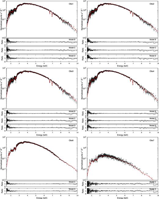
4U 1630-47 best continuum fit for all observations analysed. Red solid lines indicate the best fit obtained with model B (Obs 1–4) and model C (Obs 6–7). Lower panels indicate the data/model ratios obtained for the different models described in Table 2.
Given the results obtained from the continuum modelling, in combination with the Swift/BAT fluxes, we classify the observations into accretion states as follows. Obs 1–4 are best modelled with a diskbb with a relatively high temperature (1.49–1.58 keV) and show no significant hard X-ray flux (15–50 keV). Based on this, on their intensities, and spectral hardnesses, and on their similarity to the XMM-Newton observations analysed in Díaz Trigo et al. (2014), we classify them as being in a soft accretion state.
In contrast, Obs 6 and 7 require two-component models (diskbb and a powerlaw) to predict the Swift/BAT flux within the errors. The temperature of the disc decreases steadily from Obs 1–4 (kT ∼ 1.5−1.6 keV) to Obs 6 (kT ∼ 0.9−1.2 keV) and Obs 7 (kT ∼ 0.6 keV). In contrast, the normalization of the power law representing the hard X-ray emission first increases from Obs 1–4 to 6 by a factor >30, highlighting the departure of Obs 6 from a soft state. Obs 7 shows a drop in total luminosity of one order of magnitude with respect to Obs 6. The decrease of luminosity is accompanied again by an increase of the power-law fraction and therefore the hardness ratio, as indicated in Fig. 2. We have estimated the power-law contribution to the total unabsorbed flux in the 2–20 keV energy range for Obs 7 to be |${\sim } 65{{\ \rm per\ cent}}$| and |${\sim } 62{{\ \rm per\ cent}}$| for Models C and D, respectively. In the case of Obs 6, we have estimated the power-law contribution to the total unabsorbed flux in the 2–20 keV energy range to be |${\sim } 51{{\ \rm per\ cent}}$| and |${\sim } 49{{\ \rm per\ cent}}$| for Models C and D, respectively. As a reference, McClintock & Remillard (2006) indicates that the power-law contribution should be |$\lt 25{{\ \rm per\ cent}}$| and |$\gt 80{{\ \rm per\ cent}}$| in order to be classified as a soft and hard accretion state, respectively. Following this prescription, both Obs 6 and 7 would correspond to intermediate states. However, we emphasize that the restricted energy band imposes some limitations on our fits. As an example, we show in Fig. 4 a contour map of the N(H) and the Γ parameters obtained from Model C for Obs 6 and Obs 7. From this plot, it is clear that Obs 7 favours harder photon index compared to Obs 6. Taking all the above into account, we classify Obs 6 as being a relatively soft-intermediate state and Obs 7 as a likely hard-intermediate or hard state. Assuming a black hole mass of 10 M⊙ we have found that all observations analysed correspond to to sub-Eddington luminosities.
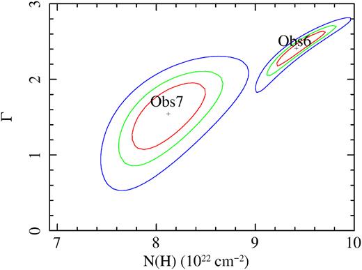
Contour plots of the N(H) and the Γ parameters obtained from Model C for Obs 6 and Obs 7.
3.2 Absorption lines
Table 3 shows the absorption lines identified in Obs 1–4, including their energies (keV), widths (σ), fluxes (photons cm−2 s−1), and equivalent widths (EWs). Common lines for Obs 1–4 include Fe xxvi Kα,Kβ, Fe xxv Kα,Kβ, Ca xx Kα. On the other hand, Ar xviii Kα, S xvi Kα, Si xiv Kα absorption lines are identified only in Obs 3 (see Table 2). We have not detected significant absorption lines in Obs 6–7, and we estimated upper limits of 1 eV for Fe xxvi Kα and Fe xxv Kα, respectively (see Table 3).
Considering the uncertainties of the measurements, we cannot identify significant changes in the line positions and EWs among the observations, except for Fe xxv Kα in Obs 3. We found that the blueshift of the lines ranges from 200 to 500 km s−1 between the different observations, consistent with values reported by Neilsen et al. (2014). We noted that the change in the energy position as well as the increase of the EW for the Fe xxv Kα line in Obs 3 is probably due to a blending of the line with Fe xxiv Kα located at ∼6.690 keV. The Fe xxv Kα/Kβ and Fe xxvi Kα/Kβ line ratios correspond to a plasma with N(H) ≳ 1023 cm−2 and νturb ≳ 200 km s−1 (table 3 of Różańska et al. 2006). Finally, the EWs distribution as function of the flux for the Fe xxv and Fe xxvi ions suggest that both Kα lines are saturated, in which case their width (i.e., their σ) may be over-estimated. However, the uncertainties of the line property measurements do not allow to be conclusive in this respect.
3.3 Photoionization modelling
Having obtained a phenomenological description of the spectra, we substitute the Gaussian components in Obs 1–4 described in Section 3.1 with the photoionization model warmabs.4 This model is part of the xstar5 photoionization code which is designed to compute the physical conditions for an ionizing source surrounded by a gas taking into account physical processes such as photoionization, electron impact collisional ionization and excitation, and radiative and dielectronic recombination. The main assumptions include ionization equilibrium conditions, a Maxwellian electron velocity distribution, and that the gas responsible for absorption and emission has an uniform ionization and temperature throughout. The warmabs model parameters include the column density of the absorber (N(H)), ionization parameter (log ξ), elemental abundances (Ax), broadening turbulence (|$v$|turb), and redshift (|$z$|). In order to perform a self-consistent modelling, we used the unabsorbed spectral energy distributions (SEDs) obtained from the continuum fits in Section 3.1 as the central source of ionizing radiation to compute the energy-level populations required by warmabs.
Table 4 shows the best-fit parameters obtained for Obs 1–4 using the same continuum as for model B (i.e., tbabs*warmabs*diskbb). Abundances were fixed to solar values for both the ISM component and the ionized absorber. As the |$\chi ^2_{\rm red}$| values indicate, this model slightly improves the fit as compared to the Gaussians described in Section 2. Fig. 5 shows the best fit obtained with the warmabs model. The main absorption features/lines included in the model are indicated. The column densities derived for Fe xxv and Fe xxvi with warmabs are N(H) > 1023 cm−2, in agreement with the line ratios obtained from the fit with Gaussians. For Obs 3, residuals around Fe xxvi Kα and Fe xxvi Kβ may indicate the presence of a second plasma component or line saturation. However, we did not find a better fit (i.e., an improvement in the statistic) by adding a second warmabs component. The best-fit warmabs parameters are very similar between the observations except for the lower log (ξ) and a lower blueshift in Obs 3. In this sense, Higginbottom & Proga (2015) have shown that variations in the luminosity and/or plasma density affect the maximum blueshift of the disc wind.
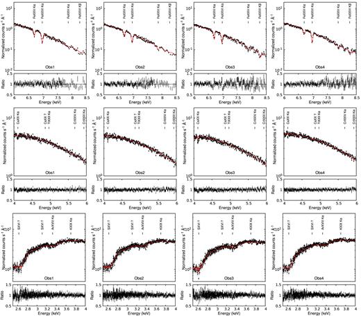
Best-fit results for Obs 1–4 modelled with warmabs (See Section 4). The main lines associated to the highly ionized absorber are indicated. The spectra have been rebinned for illustrative purposes.
Best fits to the Chandra HEG spectra for Obs 1–4 using model B but substituting the Gaussian features by a warm absorber component.
| Component | Parameter | Obs |$\#$|1 | Obs |$\#$|2 | Obs |$\#$|3 | Obs |$\#$|4 |
|---|---|---|---|---|---|
| Model: tbabs*warmabs*(diskbb) | |||||
| Tbabs | N(H) | 9.19 ± 0.07 | 9.08 ± 0.06 | 9.10 ± 0.04 | 9.16 ± 0.03 |
| diskbb | Tin | 1.54 ± 0.01 | 1.50 ± 0.01 | 1.51 ± 0.01 | 1.59 ± 0.01 |
| normdbb | 111 ± 1 | 122 ± 2 | 116 ± 1 | 103 ± 1 | |
| Warmabs | log (N(H)/1022) | 1.17 ± 0.07 | 1.29 ± 0.08 | 1.08 ± 0.12 | 1.30 ± 0.09 |
| log (ξ) | 3.99 ± 0.09 | |$4.00_{-0.14}^{+0.10}$| | 3.55 ± 0.22 | 3.92 ± 0.10 | |
| |$v$|turb | 194 ± 9 | |$148_{-13}^{+6}$| | 200 ± 27 | 157 ± 14 | |
| |$z$| | −(0.0020 ± 0.0001) | −(0.0019 ± 0.0002) | −(0.0010 ± 0.0002) | −(0.0019 ± 0.0001) | |
| Flux | (0.0136–13.60 keV) | 1.37 × 10⁻⁸ | 1.36 × 10⁻⁸ | 1.29 × 10⁻⁸ | 1.44 × 10⁻⁸ |
| Statistic | 2969/2803 | 2840/2803 | 2987/2803 | 2914/2803 | |
| red-χ2 | 1.05 | 1.01 | 1.06 | 1.03 | |
Notes. N(H) in units of × 1022 cm−2. kTin in units of keV.
normdbb = (Rin/D10)2 cos θ where Rin is the inner disc radius, D10 is the distance in units of 10 kpc,
and θ is the inclination of the disc.
Fig. 6 shows a comparison between the log (ξ), N(H), and fluxes obtained from the best fits. It is clear that Obs 3, which shows lower flux in the 0.013–13.6 keV energy range, requires both a lower column density and lower ionization parameter to be modelled. The decrease of log (ξ) to ∼3.55 leads to the appearance of absorption lines associated to ions at lower ionization state, such as Ar xviii and S xvi (see Fig. 3).
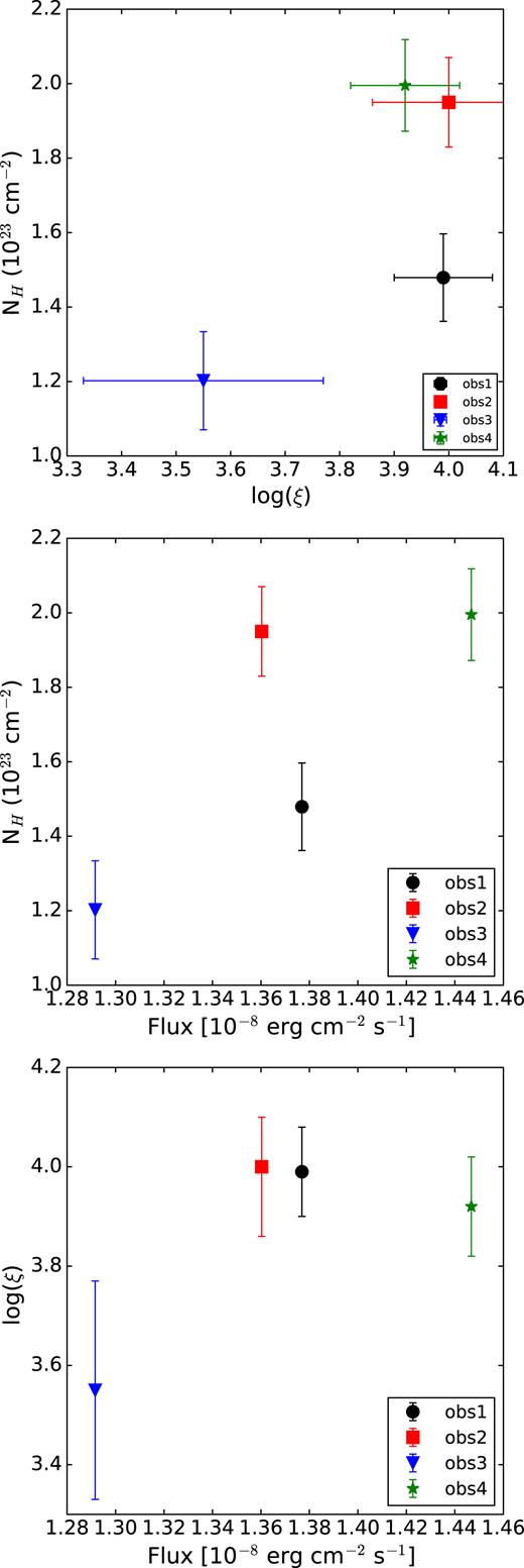
Upper panel: N(H) versus log ξ obtained from the warmabs fit for Obs 1–4. Middle panel: N(H) versus unabsorbed flux in the 0.013–13.6 keV energy range. Lower panel: log ξ versus the unabsorbed flux in the 0.013–13.6 keV energy range.
The wind launching radius can be estimated from the ionization parameter obtained with warmabs for Obs 1–4 through the well-known relation ξ = L/nr2 where L is the total luminosity in the 0.013–13.6 keV energy range, n is the hydrogen plasma density, and r is the radius of the innermost edge of the shell surrounding the source (Tarter, Tucker & Salpeter 1969). Assuming n = 1012 cm−3, we obtain values for the radius of (1.3 ± 0.1)(1012 cm/n) × 1011 cm (Obs 1), (1.3 ± 0.2)(1012 cm/n) × 1011 cm (Obs 2), (2.1 ± 0.5)(1012 cm/n) × 1011 cm (Obs 3), and (1.4 ± 0.2)(1012 cm/n) × 1011 cm (Obs 4). The n = 1012 cm assumption is derived from measuring the luminosity of the source and column density and ionization of the absorber and making the assumption that ΔR/R ∼ 1, i.e., that the thickness of the absorber is similar to its radius (see Kubota et al. 2007, section 4.3 for such a derivation). Using the same n, Kubota et al. (2007) and Díaz Trigo et al. (2014) estimated a launching radius down to one order of magnitude lower. In this sense, discrepancies are due to differences in the total luminosity obtained from the SEDs and the ξ values.
Fig. 7 shows log ξ and N(H) versus kTin obtained for Obs 1–4. For comparison, results obtained by Kubota et al. (2007) and Díaz Trigo et al. (2014) are included as well, which correspond to Suzaku and XMM-Newton observations, respectively. The plot shows that even for similar kTin, differences can be found in the log ξ and N(H) parameters obtained. Fig. 8 shows N(H) upper limits obtained with the warmabs model for Obs 6 and 7 as function of log ξ. In both cases, the continuum corresponds to model C. Clearly, the column density upper limits are very restrictive for Obs 6, with a maximum column density of 2 × 1021 cm−2 for a log(ξ) of 4.2 and even lower column densities of 5 × 1020 cm−2 for a log(ξ) < 3. For Obs 7, the column density upper limits are less constraining, especially for log(ξ) ≳ 3.8 for which column densities as high as 1.2 × 1022 cm−2 could be present. For log(ξ) < 3.8, the column density of a potential absorber is <5 × 1021 cm−2.

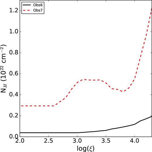
N(H) upper limits obtained with the warmabs model for Obs 6 and 7 as function of log ξ.
4 STABILITY CURVES
The equilibrium states of a photoionized plasma can be studied through the stability curve (or thermal equilibrium curve), which consists of a T versus ξ/T diagram (Krolik, McKee & Tarter 1981). When the plasma reaches a state outside the stability curve, the heating and cooling processes will compete until reaching the equilibrium. Depending on the slope of the stability curve, we can identify parts of the curve during which the slope is positive, corresponding to thermally stable regions, and negative, corresponding to thermally unstable regions.
We created stability curves using the xstar photoionization code (version 2.41) to analyse the equilibrium conditions for the plasma associated to 4U 1630-47. We ran a grid in the (log(T), log(ξ)) parameter space, with values ranging from 4 < log (T) < 10 and −4 < log (ξ) < 8. We assumed an optically thin plasma with a constant density n = 1012 cm−3 and solar abundances. For each (log(T), log(ξ)) point, the heating and cooling rates, as well as the ionic fractions for all elements, are stored. In this way, we can determine the (log(T), log(ξ)) values corresponding to a thermal equilibrium state (i.e., heating = cooling).
Because the stability curves are strongly affected by the shape of the SED (see, for example, Krolik et al. 1981; Chakravorty et al. 2009), we study the effects of all continuum models described in Section 3.1 as ionizing continuum in the xstar grid calculation. Fig. 9 shows the SEDs for the different observations and models used to generate the stability curves. For Obs 1–4, different models yield differences in the SEDs only in the high-energy region (consistent with the continuum degeneracy found in the Chandra spectra, see Table 2). In a way, we are forcing the difference in Obs 7 to be only at low energies by fixing the N(H). As explained in Section 3.1, we found that for Obs 6 the model can yield dramatically different SEDs and therefore stability curves unless we fix N(H).
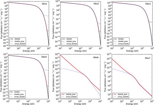
Spectral energy distributions obtained from the continuum modelling of Obs 1–4, 6, and 7.
Fig. 10 shows the stability curves obtained for Obs 1–4 using model B. The vertical line indicates the log (ξ) obtained from the best fit described in Section 3.3. In all cases, the value of log (ξ) falls within a thermally stable region of the stability curve (defined by a positive slope in such a curve). Also, due to the low fraction of photons with energies >5 × 10⁴ keV, we found no differences in the stability curves when using models C and D as ionizing SEDs. Middle and right lower panels, in the same figure, we show the stability curves for Obs 6 and 7 obtained using Model C and using Model D, respectively. For comparison, we also plot the stability curve of Obs 1. The shaded region corresponds to the uncertainties of the stability curves for heating and cooling errors of |$15{{\ \rm per\ cent}}$| while the black stars indicate the best-fit parameters obtained for Obs 1 (see Section 5.2 for an explanation about the horizontal arrows). When using model D, the stability curve is practically identical between Obs 1–4 and 6 while for Obs 7, it evolves to a higher Compton temperature and with more unstable regions, characteristic of harder SEDs. When using model C, the curve shows a lower Compton temperature and more stable regions for Obs 6, compared to Obs 1–4, but this is likely a consequence of the degeneracies in the Γ–N(H) parameters of the model (see Fig. 4).
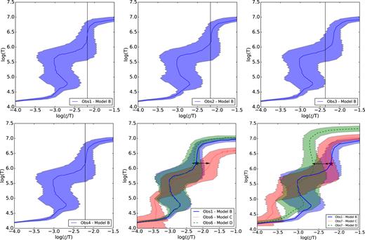
Thermal stability curves obtained for all observations. For Obs 1–4, the model B SEDs were used. Vertical lines correspond to the best-fit parameters obtained with the warmabs model. Middle and right lower panels shows the results obtained for Obs 6 and 7 using Model C (red region) and Model D (green region). In both cases, the black stars indicate the best-fit parameters obtained for Obs 1 with model B. Horizontal arrows show the possible transition between stability curves assuming nr2 = constant.
Finally, we have considered the effect of dust scattering in the spectra of 4U 1630-47, which has been reported previously (Hori et al. 2014; Neilsen et al. 2014; Kalemci et al. 2018). The overall effect of thescattering in the spectra (and therefore in the SEDs) consist of the hardening of the continuum due to the E−2 dependence of the dust model. Such an effect could be larger if dust is close to the observer. For the current observations, we have found that the inclusion of a dust scattering component (namely xscat in the xspec software) does not improve the statistic of the fits, i.e., the dust contribution cannot be determined with our observations, which are degenerate to models including or not dust scattering. However, despite the model degeneracy, the dust scattering will undoubtedly have an effect in the recovered SED. Therefore, we tested its effect in Obs 6 by performing fits including dust scattering in two extreme cases (i.e., by fixing the location of the dust to be very close and far away from the source) to compare with the model without dust scattering. In both cases, the inclusion of dust scattering makes the recovered SED softer and therefore contributes to further enforce our conclusion that the wind in 4U 1630-47 has disappeared before the SED hardens enough to cause a thermal instability.
5 DISCUSSION
We have performed a detailed analysis of six high-resolution Chandra spectra of the LMXB 4U 1630-47. We discuss below the findings of our study.
5.1 Launching mechanism
From Obs 1–4, we have estimated the launching radius of the wind to be at 1.3–2.1 × 1011 cm, although, as described in Section 3.3, such values depend on the hydrogen plasma density. It has been shown that a thermally driven wind can be launched at ∼1010–5 × 1012 cm (Begelman et al. 1983; Woods et al. 1996; Higginbottom et al. 2017). Radiative pressure due to line transitions in the UV energy band is negligible in this case due to the high disc temperature, which causes the SEDs to peak in the X-ray energy band, requiring unphysically large X-ray opacities to allow the line force to launch the wind (Proga & Kallman 2002), although Waters & Proga (2018) point to the possibility that line radiation pressure is also present in X-ray binaries. We suggest that thermal pressure is the dominant process, as was proposed by previous analyses of the source (Kubota et al. 2007; Díaz Trigo et al. 2014), and given that velocities up to ∼600 km s−1 can be reproduced with such a mechanism (see, e.g., Higginbottom & Proga 2015). In principle, a magnetically driven wind cannot be excluded (Kubota et al. 2007). However, more simulations are needed to understand if the parameters of the observed wind can be reproduced by a magnetically driven wind (see, e.g., Waters & Proga 2018, for cases where it may not).
It is important to note that the launching radius obtained from the ionization parameter depends on the SED and therefore on the continuum modelling. In addition, systematic uncertainties due to differences in the calibration of the instruments need to be taken into account when computing fluxes. Madsen et al. (2017) compute cross-normalization constants between Chandra, Suzaku, NuSTAR, Swift, and XMM-Newton instruments in the 1–3 keV and 5–7 keV energy ranges using the quasar 3C 273 and the BL Lac PKS 2155-30 as calibration sources. They found that differences in flux measurements between the instruments in these energy ranges can be up to |${\sim } 15{{\ \rm per\ cent}}$|. Also, the model degeneracy described in Section 3.1 increases the uncertainties in the flux calculation. For example, there is a factor 5 difference in the predicted 0.01–13 keV flux between Models C and D for Obs 6.
The electron density value assumed affects the launching radius estimation as well. For example, if we include the instrumental flux uncertainty (|${\sim } 15{{\ \rm per\ cent}}$|) and consider density values of 1011–1013 cm−3, we can estimate launching radii varying in the range 0.1–3.6 × 1011 cm for Obs 1–4, which then includes the values previously found by other authors.
In conclusion, because any outcome about the plasma physical conditions, such as the wind launching radius (and hence the analysis of the launching mechanism), depends on the flux obtained from the continuum fitting and on the hardness of the spectrum via the value of ξ, it is crucial (1) to construct the most accurate SED by including all information available from multiple energy bands (e.g., we included Swift/BAT measurements as a fitting constraint) and (2) to consider the uncertainties inherent to the instruments.
5.2 The disappearance of the wind
Given that disc winds are mainly found in soft states of BH LMXBs while radio jets are found mainly in hard states, it has been suggested that disc winds and jets are mutually exclusive (Neilsen & Lee 2009b). Although recent studies have shown the presence of disc wind signatures in hard accretion states (Homan et al. 2016; Muñoz-Darias et al. 2017; Allen et al. 2018), for 4U 1630-47, it is clear that the disc wind has already disappeared in Obs 6, well before reaching the hard state. Among the theories to explain the absence of a wind in the hard state are: thermal instabilities (Chakravorty, Lee & Neilsen 2013; Bianchi et al. 2017), full ionization of the plasma (Ueda et al. 2010; Díaz Trigo et al. 2012, 2014; Díaz Trigo & Boirin 2016), and disc geometry changes (Ueda et al. 2010; Miller et al. 2012; Ponti et al. 2012). However, and given that the wind has already disappeared during Obs 6, that we classify as a relatively soft-intermediate state, and Obs 7 (see Fig. 8), we next checked if any of the above reasons could be used to explain the absence of the wind.
Thermal instabilities have been proposed as explanation for the disappearance of the wind during the hard state (Chakravorty et al. 2013; Bianchi et al. 2017). Following Chakravorty et al. (2016) and Bianchi et al. (2017), if we assume that the physical properties of the plasma do not change in the transition between different accretion states (i.e., nr2 = constant), we can trace the path from the best-fit value obtained in Obs 1 to the stability curves obtained for Obs 6 and 7. These transitions are indicated in Fig. 10 by horizontal arrows. We found that, under this assumption, the best fits lie in a thermally stable region of the curve of stability when reaching Obs 6 and therefore the absence of absorption lines related to the wind is not expected due to the thermal equilibrium state of the gas predicted. In the case of Obs 7, the stability curves indicate that the best-fit parameters lie in a slightly unstable region.
Next, we checked whether the plasma could be fully ionized in Obs 6 and 7 and therefore not visible via line absorption. Fig. 11 shows the ion fractions for Fe xxiv, Fe xxv, and Fe xxvi as function of log (ξ) for the Obs 1 (solid lines), Obs 6 (dotted lines), and Obs 7 (dashed lines). It is clear from the plot that Fe xxv and Fe xxvi absorption lines should be observed for Obs 6 given the predicted ion ratios for the log (ξ) obtained when assuming the nr2 = constant condition in the transition between observations (dotted vertical line). Also, a small fraction of Fe xxvi should be observed for Obs 7, although such fraction is lower when considering models C and D.
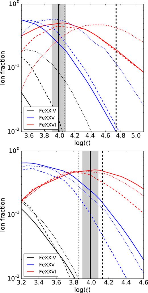
Ion fractions for the Fe xxiv, Fe xxv, and Fe xxvi ions as function of log (ξ) for Obs 1 (solid lines), Obs 6 (dotted lines), and Obs 7 (dashed lines). Top panel corresponds to the ion fractions obtained with model C for Obs 6 and 7 while bottom panel corresponds to the ion fractions obtained with model D for Obs 6 and 7. Vertical solid lines correspond to the log ξ obtained for the best fit in Obs 1 including the uncertainty Δlog ξ (gray region). The log ξ expected values obtained if the nr2 = constant condition is assumed are also included for Obs 6 (dotted vertical line) and Obs 7 (dashed vertical line), but see text for the caveats on this assumption.
This is, thermal instabilities or over-ionization cannot explain the absence of absorption lines associated to the disc wind in Obs 6 and Obs 7. However, we note that the assumption of nr2 = constant is not correct for thermal winds (Done et al. 2018). In particular, Done et al. (2018) show that during hard states, the Compton temperature is higher and, consequently, winds could be launched from radii that are smaller by up to one order of magnitude with respect to soft states. Indeed, when using model D, the Compton temperature for Obs 7 is significantly higher than for Obs 1–4 (see Fig. 10). In contrast, the assumption of nr2 = constant might be correct for our Obs 6, where a large change in the Compton temperature is not observed with the same model.
Therefore, we went on to try to find an alternative explanation for the absence of the wind in Obs 6. Dyda et al. (2017) showed that the thermal equilibrium branches of the stability curve might never be reached if insufficient flux is heating the flow. High flux cases, on the other hand, can lead to acceleration of the flow. Such acceleration produces a decrease in the column density of the plasma at given ξ and therefore the absorption lines will not be detected due to the low N(H) predicted. Dyda et al. (2017), in particular, used SEDs obtained from 4U 1630-47 Obs 6 and 7 as a template for different states of X-ray binaries. They found that for Obs 6 the absorption measure distribution, i.e., the distribution of the absorber column density with the ionization parameter along the line of sight, shows two regions with very low column densities, when adiabatic cooling becomes important. However, stable plasma regions are predicted by their model, one with 5 × 1022 cm−2 <N(H) < 1 × 1023 cm−2 for an ionization parameter 2.0 < log ξ < 2.1 and a second one with 1 × 1021 cm−2 <N(H) < 1 × 1022 cm−2 for 3.1 < log ξ < 4.0. Such lower limits for the column densities are higher than the upper limits obtained from our fits (see Fig. 8).
Given these results, we propose as an alternative possibility that the hot plasma has been exhausted during the soft state due to its continuous outflow and that ‘new’ fresh plasma could not be sufficiently heated due to the lower temperature of the disc as the source starts the transition to the hard state. Finally, we found no indications that matter has been diverted from the wind into the jet but we cannot rule out the existence of a weak jet given the upper limits obtained from our radio observations (see Section 2.2).
6 CONCLUSIONS AND SUMMARY
We have analysed six Chandra high-resolution spectra of the LMXB 4U 1630-47 obtained during the transition between soft and hard accretion states. We included Swift/BAT data in the 15–50 keV range as a constraint in the hard-energy range for the data fitting. We found that different phenomenological models can be used to fit the continuum. From the diskbb component, we estimated a disc inner radius between 33 km and 36 km (assuming a disc inclination of 75°). Absorption lines are only identified for Obs 1–4, which correspond to a soft accretion state. Common lines include Fe xxvi Kα, Kβ, Fe xxv Kα, Kβ, and Ca xx Kα while Ar xviii, S xvi, and Si xiv ions are only identified in Obs 3. We noted that the Fe xxv Kα line in Obs 3 may be blended with the Fe xxiv Kα line.
We used the warmabs photoionization model to fit the spectra of Obs 1–4. The best-fit parameters are similar between the observations except for the decreasing of log (ξ) in Obs 3, which leads to the formation of absorption lines associated to ions in lower ionization states. We inferred launching radii between (1.3 ∼ 2.0) × 1011 cm and column densities N(H) > 1023 cm−2. The launching radius indicates that thermal pressure is likely to be the dominant launching mechanism for the wind. We pointed out that discrepancies between the fluxes obtained from the continuum fitting in comparison with previous analyses of the same source can be due to instrumental systematic uncertainties as well as uncertainties in the modellng.
We computed stability curves for all observations using the xstar photoionization code. We found that the best-fit parameters obtained for Obs 1–4 lie in thermally stable parts of the curve. In the case of Obs 6 and 7, we found a solution thermally stable if we consider that nr2 = constant. In this sense, thermal instabilities cannot explain the absence of absorption lines associated to the disc wind in Obs 6, before reaching the hard state. From the radio observations, we found no indications that the jet has diverted matter from the wind. The discrepancies between the observation and predictions from photoionization models may indicate an acceleration of the flow at the end of the soft state, producing a decrease in the plasma column density, or that the plasma has been exhausted during the soft state. More observations of LMXB systems during transitional states will confirm the proposed scenarios.
ACKNOWLEDGEMENTS
The National Radio Astronomy Observatory is a facility of the National Science Foundation operated under cooperative agreement by Associated Universities, Inc. EG acknowledges support by the DFG cluster of excellence ‘Origin and Structure of the Universe’. JCAM-J is the recipient of an Australian Research Council Future Fellowship (FT140101082).
