-
PDF
- Split View
-
Views
-
Cite
Cite
Prasun Dhang, Prateek Sharma, Banibrata Mukhopadhyay, Magnetized SASI: its mechanism and possible connection to some QPOs in XRBs, Monthly Notices of the Royal Astronomical Society, Volume 476, Issue 3, May 2018, Pages 3310–3327, https://doi.org/10.1093/mnras/sty488
Close - Share Icon Share
Abstract
The presence of a surface at the inner boundary, such as in a neutron star or a white dwarf, allows the existence of a standing shock in steady spherical accretion. The standing shock can become unstable in 2D or 3D; this is called the standing accretion shock instability (SASI). Two mechanisms – advective-acoustic and purely acoustic – have been proposed to explain SASI. Using axisymmetric hydrodynamic and magnetohydrodynamic simulations, we find that the advective-acoustic mechanism better matches the observed oscillation time-scales in our simulations. The global shock oscillations present in the accretion flow can explain many observed high frequency (≳100 Hz) quasi-periodic oscillations (QPOs) in X-ray binaries. The presence of a moderately strong magnetic field adds more features to the shock oscillation pattern, giving rise to low frequency modulation in the computed light curve. This low frequency modulation can be responsible for ∼100 Hz QPOs (known as hHz QPOs). We propose that the appearance of hHz QPO determines the separation of twin peak QPOs of higher frequencies.
1 INTRODUCTION
Spherically symmetric steady-state accretion of adiabatic gas on to a point mass that can accrete the supersonically infalling gas (e.g. a black hole) is characterized by the classical transonic solution given by Bondi (Bondi 1952). On the other hand, if the central accretor has a surface that accretes very slowly, a standing shock may form within the sonic radius (McCrea 1956). For a detailed discussion, see section 5.1 of Dhang, Sharma & Mukhopadhyay (2016, hereafter Paper I).
The standing shock is stable in 1D under radial perturbations, but is unstable in 2D. The shock structure oscillates with l = 1 and higher order modes (axisymmetric sloshing modes). In the context of supernovae, Herant et al. (1994) advocated convective instability as the possible mechanism behind the oscillations of the stalled shock front. But, Foglizzo, Scheck & Janka (2006) showed that in presence of advection in the post-shock region, negative entropy gradient is no longer a sufficient condition for convective instability; advection acts as a stabilizing factor. The shock instability exists even in the absence of an entropy gradient (Blondin, Mezzacappa & DeMarino 2003; Dhang et al. 2016). Blondin et al. (2003) named this instability as standing accretion shock instability (SASI) and identified advective-acoustic feedback (Foglizzo 2002) as its possible mechanism. Later, Blondin & Mezzacappa (2006) attributed SASI to a purely acoustic cycle, and thus triggering the debate on the physical origin of SASI. Some other studies reached divergent conclusions. While studies of Ohnishi, Kotake & Yamada (2006) and Scheck et al. (2008) identified advective-acoustic cycle as the possible mechanism, Laming (2007) in his analytical studies claimed that both advective-acoustic and purely acoustic cycles can be possible depending on the ratio of the shock radius to the inner radius.
In 3D, in addition to these axisymmetric modes, SASI also shows a non-axisymmetric spiral mode (m = 1) (Blondin & Mezzacappa 2007). Fernández (2010) interpreted spiral modes as the combination of two sloshing modes, whereas Blondin & Shaw (2007) showed that sloshing modes can be constructed by combining two equal and opposite non-axisymmetric spiral modes. According to Kazeroni, Guilet & Foglizzo (2016), spiral modes dominate the dynamics of SASI only if the ratio of the initial shock radius to the neutron star radius exceeds a critical value. Otherwise, dynamics is dominated by the sloshing mode. The actual mechanism behind the shock instability is still not fully understood.
SASI has been studied extensively in the context of stellar collapse simulations over the years including different aspects of physics (e.g. neutrino transport, cooling, rotation, magnetic fields). There are state of the art realistic simulations (Burrows et al. 2006; Bruenn et al. 2006; Marek & Janka 2009) in which neutrino transport, self-gravity of stellar gas, and nuclear equation of state are considered. Also, there are simplified planar toy models of SASI without any extra physics (Foglizzo 2009; Sato, Foglizzo & Fromang 2009). Models of SASI considering the angular momentum of the infalling gas are markedly different from models without angular momentum (Blondin & Mezzacappa 2007). Spiral modes become more prominent relative to sloshing modes in presence of rotation both in linear (Yamasaki & Foglizzo 2008) and in non-linear regime (Iwakami et al. 2009). Endeve et al. (2010) and Endeve et al. (2012) explored the effects of a weak magnetic field in the absence and presence of rotation both in axisymmetric and non-axisymmetric simulations. While axisymmetric models give magnetic field amplification of the order of 2, non-axisymmetric models provide an amplification of the order of 4. They also observe that magnetic field beyond a certain strength stabilizes SASI.
As discussed earlier, different studies reached divergent conclusions by inspecting the linear properties of eigen modes, including the fundamental mode and its harmonics. In this paper, we study the physics of SASI in the non-linear regime using numerical simulations and try to shed some light on its mechanism by two different approaches: (i) by changing the ratio of the shock radius to the inner radius in hydrodynamic (HD) simulations; and (ii) by changing the magnetic field strength in magnetohydrodynamic (MHD) simulations. If SASI is an outcome of a meridional acoustic cycle, the weak magnetic field in the downstream region close to the shock should not affect the oscillation time-scales. On the other hand, a somewhat stronger magnetic field close to the centre can affect the radial advective-acoustic cycle (Guilet & Foglizzo 2010).
In Paper I, using our HD axisymmetric simulations, we proposed that SASI in accretion flows may give rise to some of the quasi-periodic oscillations (QPOs) observed in the light curves of X-ray binaries (XRBs). Most of the proposed QPO mechanisms are based on the physics of test particle motion (e.g. Strohmayer et al. 1996; Miller, Lamb & Psaltis 1998; Stella & Vietri 1999; Kluzniak & Abramowicz 2002; Kluźniak et al. 2004; Mukhopadhyay 2009), which is not affected by pressure and magnetic fields. However, for a particular model, the QPO frequencies obtained considering bulk motion significantly differ from the ones corresponding to free particles (Blaes et al. 2007). Along with our model, there are few models (e.g. Kato & Fukue 1980; Kato 1990; Ipser & Lindblom 1991; Ryu et al. 1995; Yang & Kafatos 1995; Molteni, Sponholz & Chakrabarti 1996; Chakrabarti & Manickam 2000; Wagoner, Silbergleit & Ortega-Rodríguez 2001; Mukhopadhyay et al. 2003) where bulk motion of the flow is considered to explain the origin of QPOs.
In reality, accreting matter around a compact object has angular momentum and is magnetized. As a first step, here we incorporate magnetic field and explore the origin of QPOs appearing in the light curve due to SASI in a magnetized accreting medium. This will help to understand the sole effect of magnetic field on SASI and QPOs. Our particular emphasis is QPO frequencies ≳100 Hz in XRBs, the origin of which is still not understood. We show that the presence of magnetic fields, hence magnetized SASI, appears to uncover some of the important characteristics of QPOs. In other words, the inclusion of magnetic fields introduces important physics in the SASI model to predict certain QPOs, which is absent in an unmagnetized case.
The paper is organized as follows. In Section 2, we briefly discuss the two different mechanisms proposed to explain SASI. In Section 3, we describe the physical set-up and the solution method. In Section 4, we qualitatively discuss the effects of a split-monopolar magnetic field on steady Bondi accretion. In Section 5, we describe the results obtained from our numerical simulations. In Section 6, we discuss the possible mechanism behind SASI and its astrophysical implications (in particular, QPOs), and summarize in Section 7.
2 WHAT IS SASI AND WHY?
Two different mechanisms, namely advective-acoustic and acoustic mechanisms, have been proposed to explain SASI. Most recent studies (e.g. Foglizzo et al. 2007; Foglizzo 2009) favour the former. For a comparative and detailed discussion of the two mechanisms, see Guilet & Foglizzo (2012).
2.1 Advective-acoustic cycle
Advective-acoustic cycle was first proposed by Foglizzo & Tagger (2000) in the context of Bondi–Hoyle–Lyttleton accretion. Two different waves – an outward propagating acoustic wave and an inward propagating entropy-vorticity wave – contribute to this mechanism and complete a single cycle (Foglizzo 2002, Foglizzo et al. 2007). Due to the compression of gas in the post-shock region (specially near the surface of neutron star), an acoustic wave is produced. The acoustic wave (propagation direction need not be purely radial) reaching the shock surface distorts it. The distortion of the shock surface, in turn, creates entropy-vorticity wave that advects down to the central neutron star and decelerates near the surface. Deceleration creates a positive acoustic feedback that completes the cycle. Over many cycles, the instability attains an exponential growth. With appropriate boundary conditions (like ours in this paper), the system reaches a quasi-steady state with stable non-linear oscillations.
2.2 Acoustic cycle
Acoustic cycle is thought to be driven by a trapped acoustic wave in the post-shock cavity. Blondin & Mezzacappa (2006) proposed that any density inhomogeneity produces sound waves near the shock surface. Due to refraction, these sound waves propagate around the circumference of the shock until they meet on the other side. There their excess pressure produces a shock deformation that sends another pair of sound waves back again. The growth of the mode depends on how pressure perturbation in the post shock region interacts with the shock front.
A comparison of sonic and advection time-scales should help us to distinguish these two mechanisms.
3 METHOD
To study SASI, we set up an initial value problem, in which a central accretor (e.g. a neutron star) is embedded in a stationary, spherically symmetric uniform medium. We solve the MHD equations to study the problem.
3.1 Equations solved
pluto uses a Godunov-type scheme, which solves the equations in conservative form. We use the HLLD solver with second-order slope limited reconstruction. For time-integration, second-order Runge–Kutta (RK2) is used with a CFL number of 0.4. Divergence free constraint on magnetic field is enforced by solving a modified system of conservation laws, in which the induction equation is coupled to a generalized Lagrange multiplier (Dedner et al. 2002; Mignone & Tzeferacos 2010). In this scheme, magnetic fields retain a cell centred representation.
We solve equations (1)–(4) in dimensionless form, we express our results in both code units (e.g. time-scales are expressed in units of rg/c, rg = GM/c2) and in CGS units. In the latter case, we use the central compact object mass to be 1 M⊙. It is straightforward to convert from one system of units to another.
3.2 Grid and boundary conditions
Our spherical computational domain (r, θ, ϕ) extends from an inner boundary rin = 6rg to an outer boundary rout = 104rg in the radial direction and from 0 to |$\pi$| in the meridional (θ) direction. Here, rg = GM/c2 is the gravitational radius, where G is gravitational constant and M is mass of the central accretor. We use two logarithmic grids along radial direction, one from rin to 50rg with 512 grid points and another from 50rg to rout with 256 grid points. In the meridional direction, we use a uniform grid with 256 grid points.
We fix the values of velocity components at the inner boundary; radial component vr is set to vin, whereas meridional component vθ = 0 (we obtain similar results even if vθ is copied in the inner radial ghost zones). The fiducial value of vin is 0.05c, but we change it to control the equilibrium shock radius. Density, pressure, and magnetic field components in the ghost zones are copied from the last computational zone near the inner boundary. At the outer boundary, the values of pressure, density, and velocity field components are set to their initial values. The values of magnetic field components in the outer ghost zones are copied from the last computational zone. Axisymmetric boundary conditions (scalars and tangential components of vector fields are copied and normal components of vector fields are reflected) are used at both the θ boundaries (|$\theta =0, \pi$|).
3.3 Initial conditions
4 BONDI ACCRETION WITH SPLIT-MONOPOLAR FIELD
5 RESULTS
In this section, we present results from our simulations with and without magnetic fields. We begin with results in the HD limit.
5.1 HD
To study SASI in the HD regime, we choose C in equation (5) to be very small such that the terms involving magnetic field in equations (2) and (3) vanish. We run simulations to study unmagnetized SASI with five different radial velocities imposed at the inner radial ghost zones (vin; see Table 1). We change vin to control the mean shock radius rsh, a larger value of vin gives rise to smaller rsh (for details see section 5.1 of Paper I). This way we can study SASI for different values of rsh/rin.
The radial velocity at the inner boundary, vin, mainly determines the mean shock radius rsh; rsh is calculated by taking the time average of a0 (see equation 12) in quasi-steady state. The inner boundary is fixed at rin = 6 rg; C determines the magnetic field strength; very small value of C implies that we are in the HD limit; SASI time period is measured by two different methods (see Section 5.1.3). Time-scales related to the advective-acoustic mechanism are: taac, taacA +, taacA- (equations 14, 18, 19) and that related to the purely acoustic mechanism are: trcs, tmcs (equations 15 and 16).
| Simulation details . | ||||||||||
|---|---|---|---|---|---|---|---|---|---|---|
| vin . | C . | Label . | rsh/rin . | Ta1 . | |$T_{v_{\theta }}$| . | taac . | taacA + . | taacA- . | trcs . | tmcs . |
| (c) . | . | . | . | (rg/c) . | (rg/c) . | (rg/c) . | (rg/c) . | (rg/c) . | (rg/c) . | (rg/c) . |
| 0.045 | 1 | HD | 4.65 | 808.17 | 808.90 | 732.55 | – | – | 472.73 | 718.07 |
| 0.048 | 1 | HD | 4.17 | 656.19 | 658.56 | 621.11 | – | – | 400.62 | 619.26 |
| 0.05a | 1 | HD | 3.91 | 580.24 | 581.62 | 567.42 | – | – | 368.08 | 567.81 |
| 0.06 | 1 | HD | 2.96 | 351.65 | 351.79 | 359.07 | – | – | 234.01 | 386.90 |
| 0.07 | 1 | HD | 2.35 | 240.48 | 240.46 | 242.84 | – | – | 159.39 | 280.29 |
| 0.05 | 106 | MHD | 3.90 | 579.64 | 580.35 | 567.83 | 567.17 | 568.50 | 368.70 | 566.65 |
| 0.05 | 1.25 × 10⁷ | MHD | 3.90 | 581.97 | 581.89 | 563.08 | 555.20 | 572.57 | 364.20 | 566.28 |
| 0.05 | 1.67 × 10⁷ | MHD | 3.91 | 593.26 | 592.93 | 569.09 | 555.99 | 593.25 | 369.25 | 565.96 |
| 0.05 | 2 × 10⁷ | MHD | 3.91 | 595.24 | 595.73 | 554.65 | 539.57 | 582.20 | 354.55 | 566.33 |
| 0.05 | 2.5 × 10⁷ | MHD | 3.90 | 600.91 | 600.66 | 561.84 | 543.36 | 595.85 | 362.34 | 562.42 |
| 0.05 | 3.33 × 10⁷ | MHD | 3.92 | 598.06 | 599.36 | 555.85 | 534.58 | 597.72 | 356.19 | 567.68 |
| 0.05 | 4 × 10⁷ | MHD | 3.93 | 601.56 | 601.03 | 555.91 | 531.55 | 604.24 | 355.72 | 570.24 |
| 0.05b | 5 × 10⁷ | MHD | 3.94 | 617.01 | 615.07 | 565.36 | 534.40 | 630.84 | 363.61 | 571.29 |
| 0.05 | 5.55 × 10⁷ | MHD | 3.95 | 630.83 | 629.70 | 575.86 | 541.71 | 642.61 | 372.54 | 572.71 |
| 0.05 | 6.68 × 10⁷ | MHD | 3.96 | 651.40 | 652.32 | 580.70 | 539.97 | 659.55 | 375.80 | 573.30 |
| 0.05 | 7.69 × 10⁷ | MHD | 3.98 | 667.81 | 666.94 | 583.06 | 536.02 | 680.49 | 376.37 | 576.00 |
| 0.05 | 7.94 × 10⁷ | MHD | 3.98 | 672.25 | 671.98 | 584.13 | 536.94 | 694.75 | 376.87 | 576.96 |
aThe fiducial hydro run.
bThe fiducial MHD run (Case I in Section 5.2.1).
cTwo MHD runs used only for QPO analysis with vin = 0.06c and vin = 0.048c, respectively, are not listed in the table.
5.1.1 Flow evolution
Fig. 1 shows the density snapshots at different times for our fiducial run of unmagnetized SASI. The details of flow evolution in an unmagnetized medium are described in Paper I; here, we only give a brief description. We can divide the time evolution into three phases: the early non-equilibrium phase, the intermediate transition phase, and the final quasi-stationary oscillating non-linear phase. At t = 0, the ambient medium is uniform and static. As the central gravitating object starts accreting, matter attains supersonic velocity. Both density and pressure build up near the accretor. Unlike classical Bondi accretion, here the supersonic matter falling under gravity feels an obstruction at the inner boundary as the radial velocity there is fixed at vin.

Density snapshots of the unmagnetized fiducial run at different time. Arrows represent the direction of velocity. Top left-hand panel shows the initial uniform density distribution. Due to accretion of matter from the surrounding medium, both density and pressure increase, which is shown in the second panel. Unlike the moderately magnetized case (cf. Fig. 7), the shock appears at a later time. The snapshot at t = 2685.49 (t is in units of rg/c) shows the first development of the shock surface. The next four panels (from t = 3266.13 to t = 4173.39) show radial expansion of the shock surface as well as the initial build up of the vertical oscillation modes. Then, the post-shock cavity goes through a vigorously oscillating phase (snapshots at t = 5733.88, 5879.04, and 6024.20). Finally, the system enters a quasi-stationary non-linear phase in which the post-shock cavity oscillates with a definite time period. The last five panels show a full period of coherent oscillations of global modes.
The accretion shock can be easily seen at t = 2685.49 rg/c. With time, thermal pressure builds up behind the shock due to the conversion of kinetic energy to thermal energy and shock surface starts expanding. The initial expansion is purely radial, but with time the radial expansion is accompanied by non-spherical global oscillations with l = 1 and higher order modes. This can be seen in the snapshots at t = 3919.36 rg/c, 3991.94 rg/c, and 4173.39 rg/c. As the shock becomes aspherical, it becomes oblique, resulting in the generation of meridional component of velocity (vθ) in the post-shock region (see the change in direction of velocity arrows in the post-shock region for the snapshots at and after t = 3919.36 rg/c), as the mass flux (ρv⊥) and the tangential component of velocity (v||) have to be conserved across the shock. Due to the build up of thermal pressure, the shock overcomes the inward gravitational pull and the post-shock cavity expands out (see snapshots at t = 5733.88 rg/c, 5879.04 rg/c, 6024.20 rg/c.). With the advection of mass and thermal energy across the inner boundary, after a few adjustments the systems attains a quasi-stationary state, in which the inward gravitational pull is balanced by outward thermal pressure. In this state, the post-shock cavity incessantly oscillates about the equatorial plane (the last five panels in Fig. 1 show one full oscillation period).
The equilibrium standing shock is linearly unstable to aspherical SASI modes but non-linearly the systems settle into stable, long-lived, large-amplitude oscillations. The effective potential for such oscillations can be thought of as a local maximum within a stable potential well experienced at large amplitudes.
5.1.2 Mode analysis
Shock surface can be easily identified just by looking at the density jumps in different snapshots of Fig. 1. We see that in the non-linear quasi-stationary state, shock surface can be considered as a sphere with sub-structure on top of it. To quantify the sub-structures, we perform mode analysis using the method of spherical harmonics decomposition (SHD).
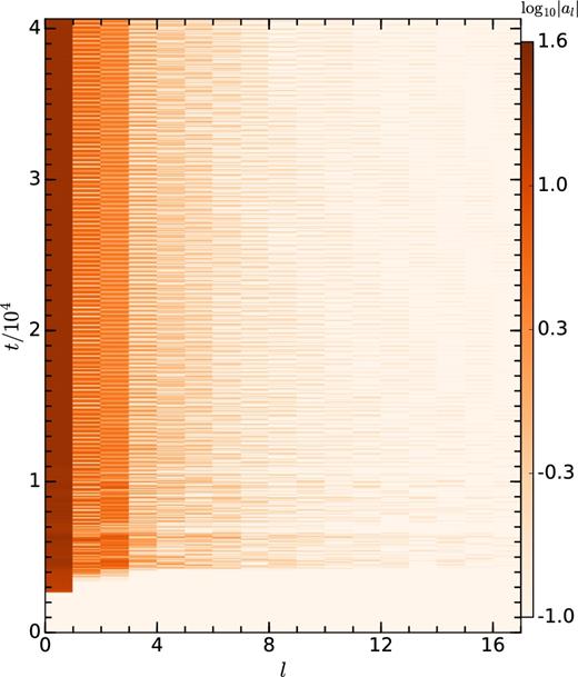
Result of mode analysis of the shock radius for our fiducial unmagnetized SASI run. Colour represents the absolute value of mode amplitude. In the quasi-stationary state, apart from the dominant l = 0 mode, l = 1, 2, and 3 modes are prominent.
5.1.3 Methods to measure SASI time period
It is clear from Fig. 1 that there are global non-linear oscillation modes associated with the post-shock cavity. We want to determine the time period of oscillations. We use two different methods to find the precise oscillation period:
Following Ohnishi et al. (2006), we fit the mode amplitude (in quasi-steady state) associated with l = 1 with a sin e curve given by ψ1 = A1 sin(ω1t + ϕ1). Time period is obtained from the value of ω1 as |$T_{a1}=2 \pi /\omega _1$|. Top panel of Fig. 3 shows the temporal variation of a1 for our fiducial unmagnetized SASI run (vin = 0.05c, C = 1). After the initial growing phase, a1 attains a quasi-steady state and oscillates about a mean value close to 0. In the bottom panel of Fig. 3, the simultaneous plots of a1 and the fitting function ψ1 are shown. The original data and the fitting function match well and the measured time period of SASI is Ta1 = 580.24 rg/c.
The second method to obtain the time period of oscillations is based on calculating the temporal variation of a local quantity at a single point in space. We choose vθ to be the local quantity because vθ changes sign as the post-shock cavity goes from the upper hemisphere to the lower hemisphere. We compute vθ(t) in the equatorial plane (|$\theta = \pi /2$|) at r = 8rg as a function of time, which is shown in the top panel of Fig. 4 for the fiducial HD run. Note that vθ(t) is not a purely sinusoidal function (see the inset in top panel of Fig. 4). To find the time period associated with it, we take the fast Fourier transform (FFT) and identify the most prominent peak in the power spectrum (defined here as simply the absolute value of the Fourier transform). To find the centroid frequency (|$f_{v_{\theta }}$|), we fit the prominent peak with a Lorentzian given by
where AL is the normalization and Γ is the full width at half-maximum. Inverse of |$f_{v_{\theta }}$| gives the oscillation period (|$T_{v_{\theta }}$|) measured by this method. Bottom panel of Fig. 4 shows the power spectrum of vθ(t); the fitting function P(f) is plotted on top of it to compare the actual and fitted values of the power spectrum. The time period of the oscillations obtained by this method is |$T_{v_{\theta }}=581.62$|rg/c. We note that both methods (i) and (ii) give almost identical results.
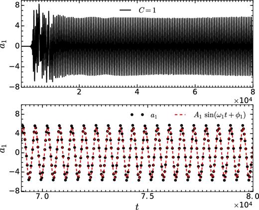
Top panel shows the temporal evolution of the l = 1 component of the shock radius (a1) for the fiducial unmagnetized SASI run. To find the time period of oscillations of global modes, a1(t) is fit with a function ψ1 = A1sin(ω1t + ϕ1). The best-fitting time period is |$T_{a1}= 2 \pi /\omega _1 = 580.24$|rg/c. Plots of a1(t) and the best-fitting function are shown in the bottom panel.
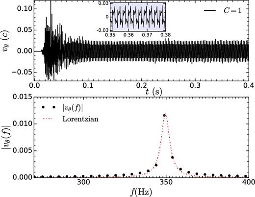
Top panel shows the temporal evolution of vθ at a fixed location (|$r=8 r_{\rm g}/c, \ \theta =\pi /2$|) for the fiducial HD run. FFT of vθ(t) (bottom panel) fitted with a Lorentzian (equation 13) gives the time period of vθ(t). Time period of the oscillations is |$T_{v_{\theta }}= 1/f_{v_{\theta }} = 581.62$|rg/c.
5.1.4 Timescales from linear theory
We measure the time period of oscillations in the quasi-steady, non-linear phase with large amplitude. Linear theories of SASI predict important time-scales related to the propagation of various perturbations. While not strictly valid, the various signal propagation time-scales are expected to provide an appropriate scaling even for the non-linear oscillations. The following arguments based on simple signal propagation time-scales stem from the fact that the disturbances have to reflect and travel back to the origin of waves to interfere and create a standing wave. In some mechanisms, mode conversion (e.g. from acoustic to vorticity/entropy modes and vice versa) is invoked at the boundaries.
Secondly, we compute the radial acoustic time-scale, sum of the times taken by the sound waves to reach the shock surface from the inner boundary and back,
Fig. 5 shows the plots of the observed time period Ta1 (since Ta1 and |$T_{v_{\theta }}$| are almost identical, we plot only Ta1) with the above time-scales obtained from linear theory for the fiducial unmagnetized SASI simulation. In the quasi-steady state, the theoretical time-scales oscillate in time with a large amplitude ( 80–300 rg/c). While both the advective-acoustic time taac and meridional acoustic time tmcs contain Ta1 within their range of variations, radial acoustic time trcs is shorter.
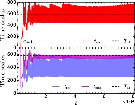
Comparison of different time-scales obtained from linear theory (namely, advective-acoustic cycle, taac; radial acoustic cycle, trcs; meridional acoustic cycle, tmcs) and SASI time period Ta1 = 580.24 for the fiducial model of unmagnetized SASI (C = 1 and vin = 0.05c). The time averaged (in the quasi-steady state) values of the time-scales are 〈taac〉 = 567.41, 〈tmcs〉 = 567.81, 〈trcs〉 = 368.03; time is in units of rg/c.
As the variations in time-scales are large, we take the time average between t = 50 000 rg/c and 82 000 rg/c. The time averaged values of advective-acoustic scales (〈taac〉 = 567.41 rg/c) and meridional acoustic time-scales (〈tmcs〉 = 567.81 rg/c) are close to the observed time period Ta1 = 580.24 rg/c. It is a coincidence that 〈taac〉 and 〈tmcs〉 are so close. Note that according to Blondin & Mezzacappa (2006), the time period of SASI oscillations is expected to be 2tmcs (so that the two waves originated at one point near the shock surface can interfere on the other side and return back to the origin), whereas we find a close match of tmcs to the measured SASI time period. On the contrary, the time averaged value of radial acoustic time is 〈trcs〉 = 368.03 rg/c, much less than the SASI time period. So there appears to be a degeneracy between the two time-scales taac and tmcs derived from two different physical mechanisms, namely advective-acoustic and purely acoustic cycles.
To break this degeneracy (between taac and tmcs) because of our choice of parameters, we change the shock location by tuning the value of vin and measure the oscillation period as well as the relevant time-scales. Top panel of Fig. 6 shows the time averaged values of velocity oscillation time period (|$T_{v_{\theta }}$|; described in (ii) in Section 5.1.3), the advective-acoustic time (taac), and the meridional acoustic time (tmcs) as a function rsh/rin. The bottom panel of Fig. 6 shows the absolute value of the difference between different relevant time-scales – (|$\Delta _{v_{\theta }, {\rm aac}} = |T_{v_{\theta }} - t_{\rm aac}|$|; |$\Delta _{v_{\theta }, {\rm mcs}} = |T_{v_{\theta }} - t_{\rm mcs}|$|; Δaac, mcs = |taac − tmcs|) – as a function of rsh/rin. For smaller rsh/rin, the advective-acoustic time (taac) matches the SASI time period measured by |$T_{v_{\theta }}$|. For larger rsh/rin, the radial advective-acoustic time-scale is shorter perhaps because of non-radial propagation of sound waves. Also note the closeness between taac and tmcs for rsh/rin ≳ 3.9, which makes it harder to choose between the two cycles in this regime.
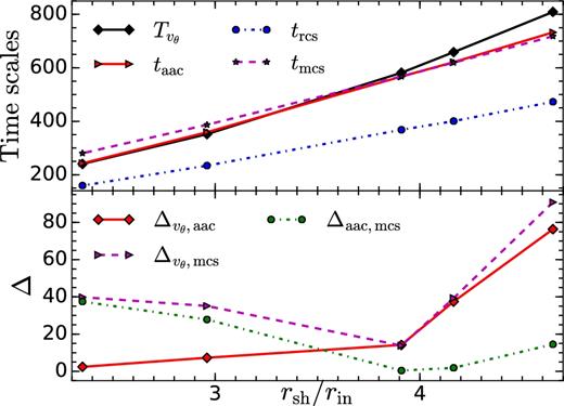
Top panel: Variation of different average time-scales (namely, advective-acoustic cycle, taac; radial acoustic cycle, trcs; meridional acoustic cycle, tmcs; and SASI time period |$T_{v_{\theta }}$|; in units of rg/c) with change in the ratio of the mean shock radius and the inner radius, rsh/rin for unmagnetized SASI. Bottom panel: Change in the absolute value of difference (Δ) between two time-scales with rsh/rin: |$\Delta _{v_{\theta }, {\rm aac}} = |T_{v_{\theta }} - t_{\rm aac}|$|; |$\Delta _{v_{\theta }, {\rm mcs}} = |T_{v_{\theta }} - t_{\rm mcs}|$|; Δaac, mcs = |taac − tmcs|. Note that of the various time-scales, the advective-acoustic time-scale most closely matches the observed SASI time period.
5.2 MHD
In this section, we present results from our simulations of initially split-monopolar magnetic fields with varying field strengths.
5.2.1 Evolution of the flow
In this section, we discuss the time evolution of the magnetized flow with the radial inward velocity at the inner boundary set to vin = 0.05c, as in the fiducial HD run. We focus on two different cases with moderate and high field strengths.
Case I: in which the magnetic field strength is moderate and SASI (identified by coherent shock oscillations) exists; this is the fiducial MHD run with C = 5 × 10⁷ (see equation 5) marked in Table 1.
Case II: in which a strong magnetic field prevents a shock from existing at late times, with C = 8 × 10⁷.
Fig. 7 shows the density snapshots for Case I. Streamlines show magnetic field lines. At t = 0, the ambient density is uniform and the magnetic pressure is comparable to the thermal pressure close to the accretor. Like the unmagnetized simulations, the magnetized runs with moderate field strengths go through three phases: an early phase in which a shock develops (top panels in Fig. 7), the intermediate transition period (middle panels in Fig. 7), and a final quasi-stationary phase (bottom panels in Fig. 7). The flow undergoes a very early transient phase (see snapshot at t = 115.77 rg/c), during which thermal pressure builds up due to the conversion of gravitational (via kinetic energy) to thermal energy, and the shock surface starts expanding radially outwards (see snapshots at t = 385.90 rg/c and at t = 2006.67 rg/c). Finally, the shock executes coherent oscillations.
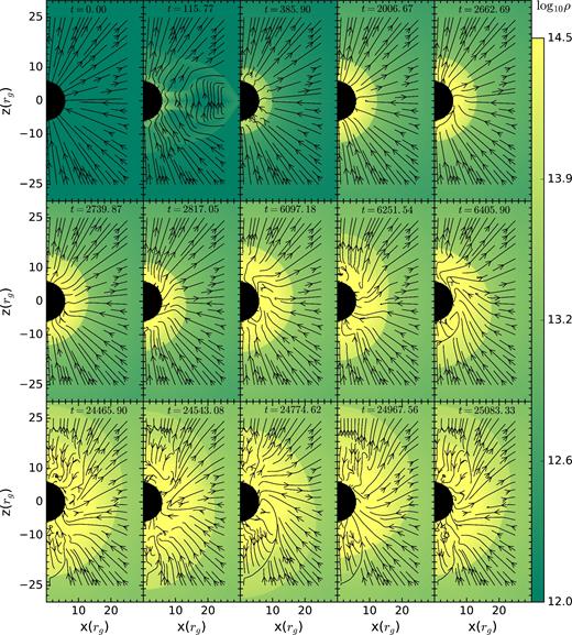
Case I: Evolution of the flow with time for the fiducial MHD run. Colour represents the density and streamlines show the magnetic field lines. First panel shows the initial uniform density distribution. A transient phase is shown in second panel. The next two panels (from t = 385.90 to 2006.67) describe growing phase of post-shock cavity. A transition period from an growing phase to an quasi-steady phase of SASI is shown in next six panels (from t = 2662.69 to 6405.90). The last five panels shows a full period of coherent oscillations of global modes. t is in units of rg/c.
Even with a slightly higher magnetic field strength (1.6 times Case I), the temporal evolution of Case II is qualitatively different because the shock is absent at late times. Fig. 8 shows the density snapshots for Case II, overplotted with arrows showing the velocity unit vectors. Like in Case I, after undergoing a transient phase (see snapshot at t = 126 rg/c), a spherical shock is formed that expands in time (see snapshots at t = 588 rg/c and 1134 rg/c). However, the shock does not stall but keeps on expanding and becoming weaker, as gravitational pull is unable to balance the outward (thermal + magnetic) pressure. When shock reaches the sonic point (rc ∼ 71 rg/c), the flow becomes subsonic and the shock disappears. Eventually, a hydrostatic atmosphere is formed. Snapshots at t = 1848 rg/c and at 2478 rg/c show the outward propagation of shock, while snapshots at t = 7182 rg/c and at 10920 rg/c show the flow structure when shock disappears.
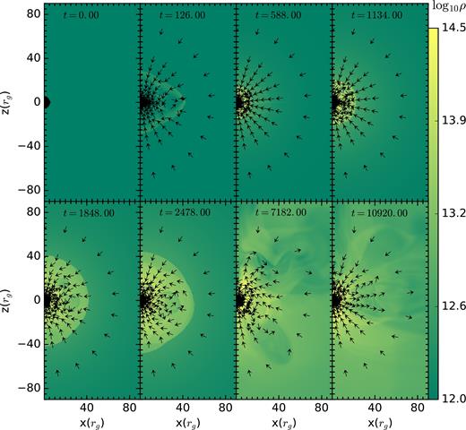
Case II: Evolution of the flow with time for C = 8 × 10⁷ and vin = 0.05c. Colour represents the density and arrows are for velocity directions. Starting with an initial uniform density distribution (left most top panel), system undergoes a transient phase (second panel on top). Then, like in Case I a spherical shock appears which grows in time (t = 588). But unlike Case I, the shock does not stall, but keeps on propagating out(t = 1134 and 1848) and loses its strength and vanishes ultimately (t = 7182.00 and 10 920). t is in units of rg/c.
Fig. 9 shows the snapshots of plasma β (the ratio of thermal and magnetic pressures) in quasi-steady state for Case I. Plasma β close to the shock surface is ≳ 103, and therefore magnetic fields are not expected to noticeably change the shock oscillation period if the underlying mechanism for SASI involves meridional propagation of fast MHD waves (generalization of sound waves in the MHD regime), characterized by the meridional acoustic time-scale tmcs (equation 16). Later, we shall see that the SASI oscillation frequency in presence of magnetic field changes noticeably (cf. black solid line with square symbols in Fig. 15), ruling out the meridional acoustic mechanism for SASI.
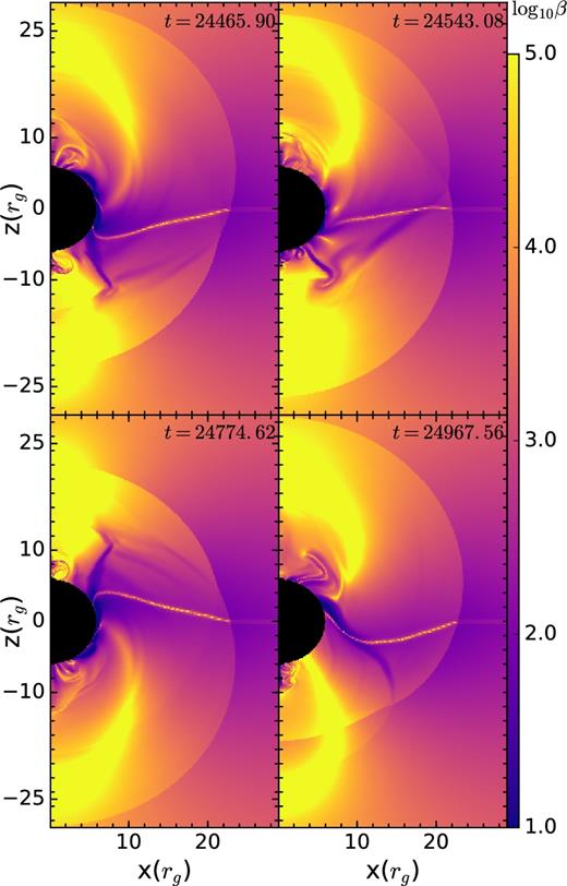
Snapshots of plasma β (≡2P/B2) at late times for Case I; t is in units of rg/c. The colour scale has been cut off at the minimum and maximum value shown in the colour bar. The inner and equatorial regions have a higher field strength. Close to the mid-plane, one can clearly see an oscillating current sheet.
The top panel of Fig. 10 shows the evolution of volume averaged magnetic and thermal energies within 30rg (top panel) with time for Cases Iand II; bottom panel shows the evolution of βV (equation 17). In the top panel of Fig. 10 for Case I, during purely radial expansion of post-shock cavity, thermal energy (yellow line) increases rapidly with time due to shock heating, but magnetic energy remains roughly constant because radial flows cannot amplify a radial field. As a result, βV increases during this phase of evolution. Later, the radial expansion of the shock is accompanied by global oscillations with l = 1 and higher order modes (see snapshots at t = 2662.69 rg/c, 2739.87 rg/c, and 2817.05 rg/c in Fig. 7). The turbulent (in transition phase) and oscillatory meridional velocities associated with non-spherical modes amplify magnetic fields at later times. Simultaneous increase of thermal and magnetic pressure causes further expansion of the post-shock cavity (in Fig. 7, see snapshots at t = 6097.18 rg/c, 6251.54 rg/c, and 6405.90 rg/c). Though, both thermal and magnetic energies increase simultaneously, the build up of magnetic energy is more erratic. Eventually, Case I attains a quasi-stationary state, in which both thermal and magnetic energies start oscillating about a mean value.
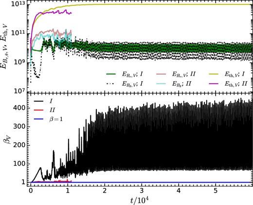
Top panel: Temporal evolution of average (over the volume V enclosed within r = 30rg) thermal energy Eth, V and magnetic energies associated with radial (|$E_{B_{r},V}$|) and meridional (|$E_{B_{\theta },V}$|) components of magnetic field for Case I and Case II. Bottom panel: Temporal evolution of the βV, the ratio of volume averaged gas pressure (P) to magnetic pressure (B2/2) for the same runs. While time averaged βV in quasi-stationary state is ∼300 and shock persists, in Case II due to presence of stronger initial magnetic field, the flow gets choked and the final βV ∼ 5 and shock disappears at late times.
For Case II, magnetic field amplification happens earlier compared to Case I due to presence of aspherical shock from the very beginning of the flow evolution (see snapshots at t = 126 rg/c, 588 rg/c, and 1134 rg/c in Fig. 8). Once shock disappears, magnetic energies (both |$E_{B_r, V}$| and |$E_{B_{\theta },V}$|) saturate. This early amplification of magnetic field results in a low βV (close to ∼5) during the flow evolution which, in turn, chokes the flow. The temporal evolution of the flow in Case II is equivalent to a hydro set-up with reflective inner radial boundary condition, or more precisely, if vin is smaller than the lower limit of velocity (at the inner boundary) for which a stationary shock solution is possible (see fig. 15 and section 5.1 in Paper I).
5.2.2 Mode analysis
Fig. 11 shows the evolution of mode amplitudes al (measured by decomposing the shock radius into spherical harmonics; see Section 5.2.2) with time for the Case I MHD run. As in HD evolution, l = 0 is always the dominant mode. But unlike HD, during the very early evolution of the flow (t < 400rg/c), all the even order modes (l = 2, 4, 6 etc.) are more dominant compared to the odd modes (l = 1, 3, 5 etc.). This can be attributed to the anisotropic nature of the initial transient phase of evolution, which is symmetric about |$\theta =\pi /2$| (see snapshot at t = 115.77rg/c in Fig. 7). When the post-shock cavity attains an almost spherical shape and starts expanding radially, contribution from even order modes with l ≥ 2 becomes negligible. As the shock starts oscillating vertically about the equatorial plane, l = 1 mode starts to dominate the higher order modes. In the fully non-linear quasi-steady regime, apart from the l = 0 mode, l = 1, 2 and 3 are the most prominent modes.
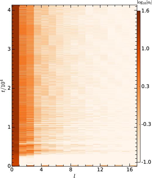
Results of mode analysis for the fiducial MHD run. Colour represents the absolute value of mode amplitude. l = 0 is the most dominant mode at all time. During the very early transient phase, only even modes (l = 0, 2, 4,6 etc) dominate. After the transient phase, during pure radial expansion of shock, only l = 0 mode dominates. As soon as shock-structure starts oscillating in the vertical direction, apart from l = 0 mode, l = 1, 2 and 3 modes dominate over the higher order modes.
Comparing Fig. 11 and Fig. 2, it is very difficult to quantitatively study the differences in modal contribution of the HD and MHD runs. Fig. 12 shows the temporal evolution of a0 (see equation 12), a measure of spherical radius of the aspherical shock, for different magnetic field strengths. At the very early stage of evolution, a large value of a0 reflects the transient phase at t = 115rg/c (see Fig. 7). After the transient phase, a spherical shock emerges, and the value of a0 drops. After showing large fluctuations in a0 in the transition phase, the shock attains a quasi-stationary state with a0 oscillating about a mean value. The inset at top right-hand side shows the zoomed-in view of a0(t) in steady state. As expected, the average shock radius increases with an increase in the magnetic field strength. Even in the quasi-steady state, a0 does not show sinusoidal variation at a single frequency.
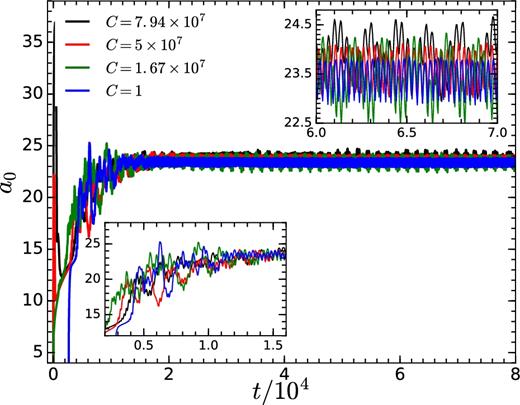
Temporal evolution of the amplitude a0 (mean shock radius) of l = 0 mode for different initial strength of magnetic fields and vin = 0.05c. Zoomed-in view of the initial phase is shown in inset figure on bottom left-hand side. The inset figure on the top right-hand side shows the zoomed-in view of the quasi-steady phase. Shock radius increases with time and eventually settles into an oscillating value. The mean shock radius is larger for a stronger field (see inset in the top right-hand side)
Fig. 13 shows the variation of time-averaged mode amplitude for l = 0, 1, 2, and 3 with the initial magnetic field strength. For a0 and a2, we take time average in the quasi-steady state. For l = 1 and 3, as a1 and a3 oscillate about a vanishing mean value, we fit the quasi-steady a1(t) and a3(t) with a sinusoidal curve, and plot the variation of the amplitudes A1 and A3 with the magnetic field strength. As expected, Fig. 13 shows that a stronger magnetic field suppresses the higher order modes due to higher magnetic tension.
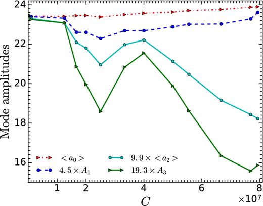
Variation of mode amplitudes al with initial magnetic field strength (quantified by C) for vin = 0.05c. For l = 0 and 2 modes, amplitudes (a0 and a2, respectively) are time averaged in the quasi-steady state. For l = 1 and 3, the amplitudes A1 and A3 are obtained by fitting a1 and a3 with fitting functions, ψ1 = A1sin(ω1t + ϕ1) and ψ3 = A3sin(ω3t + ϕ3), respectively.
5.2.3 Timescales from linear theory
Any disturbance in HD is carried by either sound waves propagating at ±cs relative to the inflow or by entropy/vorticity waves travelling at the local flow velocity. In MHD, the sound wave generalizes to the fast mode and the entropy mode still consists of perturbations in total (thermal+magnetic) pressure balance. However, there are two new modes in MHD: the shear Alfvén wave and the slow magnetosonic waves. Therefore, the advective part of the advective-acoustic cycle is expected to split into five different cycles: an entropy wave, two Alfvén waves, and two slow magnetosonic waves (Guilet & Foglizzo 2010).
To interpret the SASI oscillation time-scales in presence of magnetic fields, we compute two more time-scales in addition to the three time-scales introduced in Section 5.1.4. For computing time-scales in the MHD set-up, we assume that for radial propagation (wave-vector |${\boldsymbol k} || {\boldsymbol B_0}$|; fields are roughly radial even in the quasi-steady state as seen in Fig. 7), vslow ≈ vA and vfast ≈ cs (valid for cs > vA; see equation 19 in chapter 5 of Kulsrud 2005; Fig. 9 indeed shows that β ≫ 1 throughout), and for meridional propagation (|${\boldsymbol k} \perp {\boldsymbol B_0}$|), |$v_{\rm fast} \approx \sqrt{c^2_{\rm s} + v^2_A}$|.
Fig. 14 shows the temporal variation of all the relevant time-scales for the fiducial MHD run (Case I). While Ta1 = 617.01 rg/c (SASI time-scale measured by the period of l = 1 perturbation in the shock location) still lies in the range of variations of taac, taacA +, and taacA- (equations 14, 19 and 18) related to the advective-acoustic cycle, it is longer than the meridional and radial sonic time-scales, tmcs and trcs (equations 16 and 15).
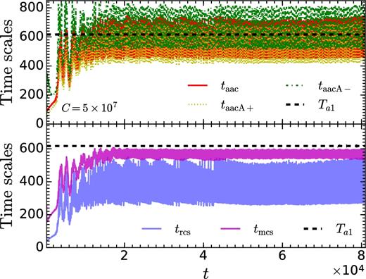
Various time-scales as a function of time for fiducial MHD run. The observed time period of oscillation Ta1 = 617.01. Time averaged value of time-scales are 〈taac〉 = 565.36, 〈trcs〉 = 363.61 〈tmcs〉 = 571.29, 〈taacA +〉 = 534.40, 〈trcs〉 = 630.84. Time-scales are expressed in units of rg/c.
Fig. 15 shows the variation of SASI time period (measured by both methods, Ta1 and |$T_{v_{\theta }}$|; see Section 5.1.3) and the time-averaged time-scales (obtained from various signal propagation time-scales) as a function of the initial magnetic field strength (quantified by C; see equation 5). While the maximum relative change (compared to HD) in SASI time period is |${\approx } 15.84 \,\,\rm{per\,\,cent}$|, that in tmcs is only |${\approx } 1.75 \,\,\rm{per\,\,cent}$|. In presence of a weak magnetic field (β ≫ 1), SASI time period is not expected to be affected if the mechanism is purely acoustic. Even the variation in the HD advective-acoustic time-scale is small. However, the taacA- time-scale in which the inward-propagating signal travels at |$|\bar{v}_r|-\bar{v}_A$| (i.e. Alfvén wave travels outwards relative to the flow) matches the variation of the observed SASI time-scale fairly well. In principle, the inward propagating signal should consist of five waves (Guilet & Foglizzo 2010), but a cycle consisting of outward propagating fast waves and inward-propagating Alfvén disturbances (travelling inward at |$|\bar{v}_r|-\bar{v}_A$|) seems to quantitatively describe the shock oscillations observed in our simulations.
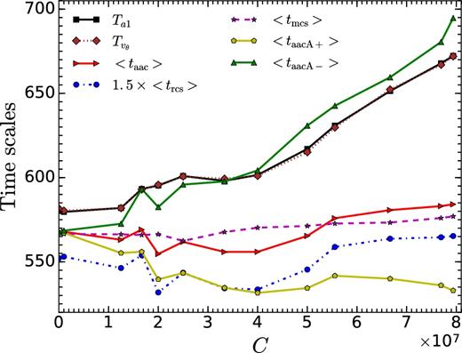
Variation of the observed time period of oscillation (Ta1 and |$T_{v_{\theta }}$|) and average (over time in quasi-steady state) signal propagation time-scales (taac, trcs, tmcs, taacA +, taacA-; equations 14, 15, 16, 18 and 19) as a function of the initial magnetic field strength (C) for vin = 0.05c. Time-scales are expressed in units of rg/c.
6 DISCUSSIONS AND CONCLUSIONS
In this paper, we describe the effects of an initial split-monopolar magnetic field on the SASI. Now, we discuss the key results of our work and draw conclusions.
6.1 Flow structure
In Section 4, we showed that a radial magnetic field does not modify the Bondi accretion solution. In this section, we discuss how the flow structure changes in the saturated state for vin = 0.05c and different magnetic field strengths. Beyond a certain magnetic field strength (for vin = 0.05c, the critical value is C = 7.94 × 10⁷), SASI does not occur. We choose four different strength of magnetic field: C = 1, unmagnetized; C = 5 × 10⁷, moderately magnetized; C = 7.94 × 10⁷, the strongest magnetic field for which SASI occurs and C = 8 × 10⁷, the strength of magnetic field at which SASI cannot occur.
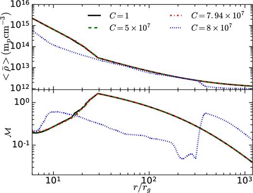
Top panel: θ− and time averaged density profile for different initial magnetic field strengths – C = 1 (almost unmagnetized), C = 5 × 10⁷ (moderately magnetized), C = 7.94 × 10⁷ (the strongest magnetic field for which SASI can occur), and C = 8 × 10⁷ (magnetic field strength at which SASI cannot occur). Bottom panel: Mach number |$\mathcal {M}= -\langle \bar{v}_r\rangle /\langle \bar{c}_s\rangle$| as a function of r for different value of C.
where T is the averaging period. We represent time average by ‘〈〉’ and θ− average by ‘−’. Top panel shows the average density as a function of r. For magnetic field strengths that allow SASI, radial density profiles fall on top of each other, irrespective of the magnetic field strength. This implies that the local flow structure may be different for different field strengths, but on average the flow structures are identical. Bottom panel shows the radial profile of local Mach number |$\mathcal {M}= -\langle \bar{v}_r\rangle /\langle \bar{c}_s\rangle$|. Here, also for all three magnetic field strengths for which SASI occurs, profiles are identical. But for C = 8 × 10⁷, for which an oscillating shock does not occur, the density and Mach number profiles are different from the other three cases. The roughly hydrostatic flow is unsteady but eventually expected to asymptote to the settling flow described by lower branch in Bondi solution (see the first panel of fig. 14 in Paper I).
Thus, strong magnetic field beyond a critical strength chokes the flow, reducing the effective vin. In our idealized model, for the same sonic radius rc, the critical magnetic field strength depends on the advection velocity at the inner boundary vin, which determines the shock radius. Larger the vin, higher the advection of thermal and magnetic energies through the inner boundary. As a result, gravity can counter stronger magnetic pressure (within post-shock cavity) which acts outward along with the thermal pressure.
6.2 SASI mechanism
Unlike most of the previous simulations, our set-up leads to a quasi-steady state in which the non-linear oscillations essentially last forever. We compare the SASI time period with time-scales obtained from two different mechanisms (namely advective-acoustic and purely acoustic) in HD and MHD.
In HD regime, we change the ratio of mean shock radius (rsh) to inner radius (rin) keeping rin fixed, and study the variation of different time-scales with this ratio. For small values of rsh/rin, the match between the advective-acoustic time-scale taac and the SASI time period (|$T_{v_{\theta }}$| or Ta1) is excellent. With an increase in rsh/rin, the deviation of the time-scale becomes larger (see Fig. 6). Purely acoustic mechanism gives rise to two different time-scales: the radial acoustic time trcs (considering purely radial propagation) and the meridional acoustic time tmcs (considering meridional propagation). In all cases, trcs is always much less than the SASI time period, so we can discard purely radial acoustic mechanism as the possible cause for SASI. The match between the tmcs and SASI time period becomes best around rsh/rin ∼ 3.9. But it is to be noted that according to Blondin & Mezzacappa (2006), SASI time period is expected to be equal to the round trip time of two sound waves advancing along the shock surface i.e. 2tmcs. Instead, we observe the closeness between tmcs and SASI time period.
In MHD regime, we study the variation of SASI time-scales with the change in initial magnetic field strength. In presence of a weak magnetic field, the advective-acoustic cycle is expected to split into five different cycles that constitute the actual cycle (see Section 5.2.3). We compute three time-scales to quantify five cycles, taac – outgoing fast magnetosonic wave + ingoing entropy wave, taacA + – outgoing fast magnetosonic wave + ingoing (with respect to local inflow) Alfvén/slow wave, taacA- – outgoing fast magnetosonic wave + outgoing (with respect to local inflow) Alfvén/slow wave. While the maximum relative change (to HD) in time-scales obtained from the advective-acoustic mechanism is |$\approx 18 \,\,\rm{per\,\,cent}$| (for taacA-), in the meridional acoustic mechanism it is only |${\approx } 1.75 \,\,\rm{per\,\,cent}$| (for tmcs), compared to the change in SASI time period of |${\approx } 15.84 \,\,\rm{per\,\,cent}$|. In purely acoustic mechanism, weak magnetic fields do not affect the SASI time period, but in advective-acoustic mechanism weak magnetic fields affect the SASI time period. The effects depend on the ratio vA/vr, the ratio of Alfvén, and radial advection speeds.
Both in HD and MHD regimes, advective-acoustic mechanism is favoured as the possible mechanism for SASI. Further, if SASI is a purely acoustic mechanism, the dispersion relation in the local limit is given by ω = kcs, which means that the frequency of different modes should be proportional to the wavenumber. To find the frequency associated with different modes, we take the temporal FFT of shock deformation modes (al(t)) and best fit the lowest frequency peak with a Lorentzian (equation 13); centroid frequency gives the frequency of the corresponding mode. Fig. 17 shows the representative examples of FFT of al for l = 0, 1, 15, and 16 for our fiducial hydro run. Bar plot in Fig. 18 shows the variation of mode frequency with mode number. All the even modes (l = 0, 2, 4 etc.) have frequency ≈700 Hz, and odd modes (l = 1, 3, 5 etc.) have frequency ≈350 Hz, which is against the expectation f ∝ l for acoustic signals.
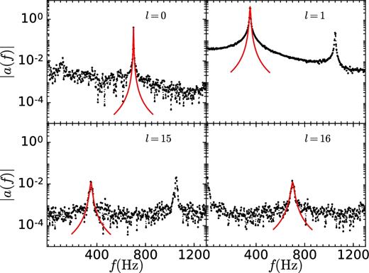
FFT of the mode amplitudes al for l = 0, 1, 15, 16 for the fiducial hydro run. The lowest frequency peaks are fitted individually by a Lorentzian using the least squares fit method. Centroid of the Lorentzian gives the frequency associated with the corresponding mode.
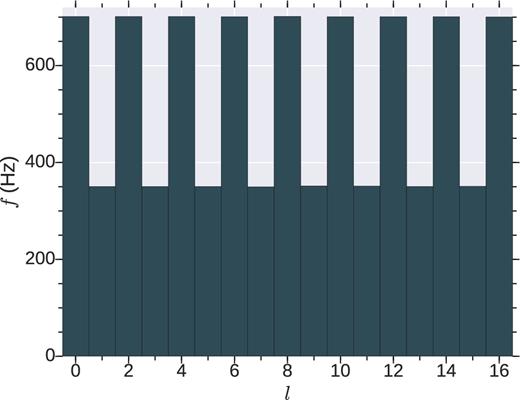
Lowest frequency associated with different modes (l) of oscillation for the fiducial HD run.
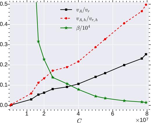
The ratio of average Alfvén speed (vA) to average advection speed (vr) and ratio of gas pressure to magnetic pressure (β) with initial magnetic field strength (C). For vA/vr and β, average is done over whole post-shock volume, whereas for vA, h/vr, h, average is done within the half shock radius.
Equation (21) tells that for the same strength of magnetic field, the higher order modes are more affected compared to lower order modes, which is clear from Fig. 13. We also see that the SASI period is not a monotonically increasing functions of magnetic field strength; there are irregularities that are expected in the framework of advective-acoustic mechanism due to interference of different cycles (see fig. 6 of Guilet & Foglizzo 2010).
So, we conclude that the physical mechanism behind SASI (at least in the parameter regime that we explored) is more likely to be the advective-acoustic mechanism instead of a purely acoustic mechanism (either meridional or radial).
6.3 QPOs and SASI
SASI in an accretion flow gives rise to an intrinsic time variability in the flow, which may explain some of the QPOs observed in XRBs. In this section, we try to connect different time-scales associated with magnetized SASI with different high frequency (HF ≳ 100 Hz) QPOs observed in XRBs (both in black hole and neutron star binaries).
Kilohertz (kHz) QPOs are the fastest variability components in neutron star XRBs (van der Klis 2004), seen in most Z and atoll sources. Sometimes kHz QPOs appear in pairs; the peak with the higher frequency is called the upper kHz QPO at frequency fu and the other is called lower kHz QPO with frequency fl. Many models associate orbital motion in the disc with one of the kHz QPOs (Strohmayer et al. 1996; Miller et al. 1998; Mukhopadhyay et al. 2003). While Mukhopadhyay et al. 2003 attributes global shock oscillations as the origin of upper kHz QPOs for the first time, some other models argue that both QPOs arise via non-linear resonance between fundamental frequencies, e.g. between radial and vertical epicyclic oscillation frequencies along with the spin frequency of neutron star (Kluźniak et al. 2004; Pétri 2005; Blaes et al. 2007; Mukhopadhyay 2009). Parametric resonance models are particularly attractive if fu − fl is linked with the spin frequency νs of the neutron star, when fu − fl ∼ νs/2 (if νs ≳ 400 Hz; e.g. KS 1731−260, 4U 1636−53) or fu − fl ∼ νs (if νs ≲ 400 Hz; e.g. 4U 1728−34, 4U 1702−429) (Strohmayer et al. 1996; van der Klis et al. 1996; Ford et al. 2000; Wijnands et al. 2003). However, later on this interpretation was questioned (Méndez & Belloni 2007).
For black hole sources, on the other hand, the observed twin HF QPOs are often argued to be seen in 2 : 3 ratio [e.g GRO J1655−40 (300, 450 Hz; Remillard et al. 1999; Strohmayer 2001), XTE J1550−564 (184, 276 Hz; Homan et al. 2001), and GRS 1915+105 (113, 168 Hz; Remillard 2004)], which again was explained based on non-linear resonance by the groups mentioned above. Some recent observations question the 2 : 3 appearance of HF QPOs in black hole XRBs [e.g IGR J17091−3624 (66, 164 Hz; Altamirano & Belloni 2012)].
Another ≳100 Hz variability phenomenon is the hectohertz (hHz) QPO (Ford & van der Klis 1998) with a frequency fhHz in the range 100–270 Hz (e.g see Altamirano et al. 2008) in atoll sources in most states. Fragile, Mathews & Wilson (2001) proposed that accreting material passing through the transition region formed due to Bardeen–Petterson effect may generate hHz frequencies. Kato (2007) proposed that a warp in accretion disc gives rise to the hectohertz QPOs in atoll sources. The black hole sources also exhibit QPO frequency of order hHz or slightly less, e.g. GRS 1915+105, XTE J1550−564, simultaneously with HF ones (e.g. Remillard et al. 2002). Earlier non-linear resonance models can be modified to explain it (Mukhopadhyay, Bhattacharya & Sreekumar 2012).
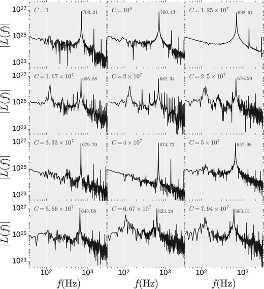
Power spectrum of the light curves assuming free–free emission for different magnetic field strength (C) and vin = 0.05c. With the increment in magnetic field strength, low frequency features appear and disappear non-monotonically. The most prominent peak whose frequency is the frequency of l = 0 mode and half the frequency of l = 1 mode can be related to upper kHz QPO. For some strengths of magnetic field, alongside the main peak, there are some comparatively low frequency peaks that can be related to some other types of HF QPOs such as lower kHz QPO and hHz QPO.
where V is the spherical volume of radius r = 30rg, dominated by post-shock region. The post-shock temperature in simulations is very high (T ∼ 1011K). The electrons in hot accretion flows are at lower temperature compared to that of the ions and other emission process may be important (e.g. Sharma et al. 2007; Rajesh & Mukhopadhyay 2010; Yuan & Narayan 2014). Therefore, light curves from simulations (which assume a single temperature fluid) should be only taken as trends.
First panel of Fig. 20 shows the power spectrum for the unmagnetized (C = 1) SASI run and the power spectrum has the most prominent peak at f0 = 700.24 Hz along with its harmonics (the peak frequency is obtained by fitting with a Lorentzian). This is the frequency associated with the l = 0 mode and double the frequency of l = 1 mode. There is some low frequency noise present in the power spectrum. With the increase in magnetic field strength, the prominent peak frequency shifts to lower value and the low frequency noise becomes less prominent (for C = 106) and vanishes for C = 1.25 × 10⁷. As the magnetic field strength is increased more, some extra peaks arise at low and intermediate frequencies along with the main peak (e.g. C = 1.67 × 10⁷ and 2 × 10⁷). The lowest frequency is associated with the modulation frequency on top of a regular frequency of mode amplitude a0(t) (e.g. see the variation of a0(t) for C = 7.94 × 10⁷ in Fig. 12). With the increase in magnetic field strength, low frequency features appear and disappear non-monotonically.
In this analysis, the origin of QPOs (whether kHz, HF or hHz) is different from past proposals. Fig. 21 shows the power spectrum for C = 2 × 10⁷ and vin = 0.05c. The most prominent peak appears at 681.78 Hz, which can be related to the upper kHz QPOs at fu. The lowest frequency peak is at 135.96 Hz, which can be identified as the hHz QPO at fhHz. In between these two peaks, there are three more peaks. One of them is the harmonic of the hHz QPO (fhHz2 = 273.44 Hz ≈2fhHz), other two peaks are the beat frequencies, fl1 = 545.40 Hz ≈fu − fhHz and fl2 = 408.21 Hz ≈fu − fhHz2, one of which can be related to the lower kHz QPO. Whereas, fu is equal to the frequency associated with l = 0 mode, fhHz is the frequency of modulation in the mode amplitude a0 due to magnetic field, as seen in inset at upper right-hand side of Fig. 12. With magnetic field strength (C), the upper kHz QPO frequency fu tracks 2/Ta1, the frequency of l = 0 mode (which is double the l = 1 mode frequency). For all field strengths, the hHz QPO frequency remains constrained in the range (110–135) Hz.
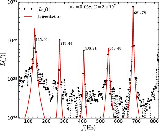
Power spectrum of light curve for vin = 0.05c and C = 2 × 10⁷. The prominent peaks appears at fu = 681.78 Hz, fhHz = 135.96 Hz, and at its harmonics, fhHz2 = 273.44 Hz, and at the beat frequencies, fl1 = 545.40 Hz∼ fu − fhHz, fl2 = 408.21 Hz∼ fu − fhHz2. The peaks are fitted individually by Lorentzians using least squares fit method.
If the shock location is changed by tuning the value of vin, SASI time period changes (as shown in Fig. 6), so does fu, as fu ≈ 2/Ta1. On the other hand, the hHz QPO arises due to magnetic effects. To see the variation in fhHz with the change in shock location, we decrease and increase the shock radius by changing vin to 0.06c and 0.048c, respectively. For vin = 0.048c, power spectrum of the light curve for C = 2 × 10⁷ is shown in Fig. 22; three peaks are present in the power spectrum. Upper kHz QPO frequency fu = 599.90 Hz is shifted to a lower value compared to the fiducial case (vin = 0.05c), so does the hHz QPO frequency (fhHz = 105.22 Hz). The frequency of lower kHz QPO is fl = 495.82 Hz ≈fu − fhHz. Fig. 23 shows the power spectrum of light curve for vin = 0.06c and C = 5 × 10⁷, with a smaller shock radius. As expected, the upper kHz QPO frequency (fu = 1081.10 Hz) related to SASI time period increases. Also, the hHz QPO frequency (fhHz = 225 Hz) moves to a higher value. The lower kHz QPO (fl = 869.54 Hz) structure becomes fainter (this might be immersed in noise in real observations).
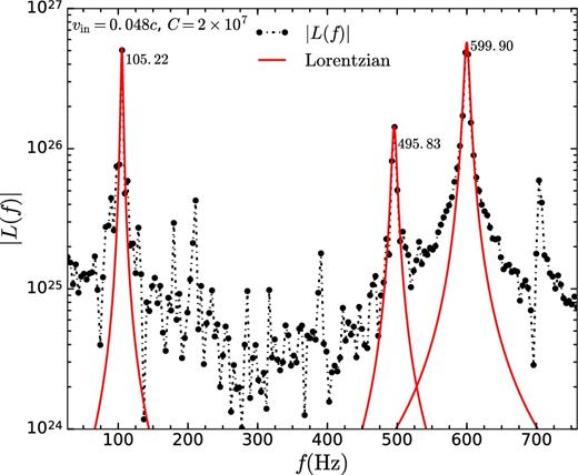
Power spectrum of light curve for vin = 0.048c and C = 2 × 10⁷. The prominent peaks appear at fu = 599.90 Hz, fhHz = 105.22 Hz, and at the beat frequency of the former two, fl = 405.82 Hz∼ fu − fhHz. The peaks are fitted individually by Lorentzians using least squares fit method.
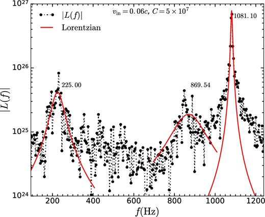
Power spectrum of light curve for vin = 0.06c and C = 5 × 10⁷. The most prominent peaks appear at fu = 1081.10 Hz, and at fh = 225 Hz, which can be considered as upper kHz QPO and hHz QPO, respectively. A fainter peak is seen at fl = 869.54 Hz, which can be considered as lower kHz QPO. The peaks are fitted individually by Lorentzians using least squares fit method.
Our idealized simulations suggest shock oscillations as the origin of QPOs. in particular kHz/HF/hHz ones. We identify the l = 0 SASI mode frequency (which is double the frequency of l = 1 mode) as the frequency of upper kHz QPO. It is the appearance of the hHz QPO that determines the separation of twin QPO peaks. We do not observe the hHZ QPOs in our simulations without magnetic fields, indicating that they originate only in the presence of a magnetic field. Hence, one does not necessarily need to introduce the spin of the compact objects to explain QPOs.
6.4 Caveats of the model
The present model is very simplistic. In reality, accretion flows have complicated magnetic field geometry, angular momentum, cooling (depending on the spectral state of the XRBs), which might change the above results. A brief discussion of the above-mentioned factors is given below.
We initialize the simplest magnetic field configuration, a split-monopole. Because of the absence of magnetic force in the pre-shock flow, the equilibrium is not affected by the magnetic field (see Section 4), but the mode frequencies are. The mode frequencies are expected to behave differently for different field geometries (Guilet &Foglizzo 2010).
Accreting matter in XRBs is expected to have angular momentum. QPOs are observed in the hard state, in which the inner flow is expected to be hot, quasi-spherical, and sub-Keplerian (e.g see Chakrabarti 1989). To approximate that we study the spherical, adiabatic, non-rotating accretion flow on to a compact object. However, even small angular momentum can affect the global shock oscillations (Blondin & Mezzacappa 2006; Yamasaki & Foglizzo 2008; Kazeroni, Guilet & Foglizzo 2017). Shock instabilities in rotating accretion flows were invoked to explain time variability (mostly low frequency phenomena) in accreting systems (Molteni et al. 1996; Nagakura & Yamada 2009).
We also assume axisymmetry, breakdown of which may significantly alter the oscillation frequencies. While in the non-rotating flow, non-axisymmetric modes of SASI redistribute angular momentum (Blondin & Mezzacappa 2007; Fernández 2010; Guilet & Fernández 2014; Kazeroni et al. 2016), in a rotating flow the spiral modes become more prominent over the sloshing modes (Iwakami et al. 2009; Kazeroni et al. 2017) and dominate the dynamics of the flow. The occurrence of non-axisymmetric Papaloizou-Pringle instability (Papaloizou & Pringle 1984), its interplay with the advective-acoustic cycle (Gu & Foglizzo 2003), and the magneto-rotational instability (Balbus & Hawley 1991) are additional complications in a rotating accretion flow.
We also neglect radiative cooling because in the hard state the inner accretion flow is expected to be hot and non-radiative with the cooling time much longer than the infall time of the flow. Some earlier studies showed that the shock is unstable even in 1D in presence of cooling (Langer, Chanmugam & Shaviv 1981; Chevalier & Imamura 1982; Saxton 2002), but our non-radiative simulations require 2D or 3D to be unstable (see Paper I).
We expect shock oscillations in inner, hot, transonic accretion flows (rotating or non-rotating). But for comparing with the observations, one needs to study them in more realistic 3D simulations with rotation, magnetic fields.
7 SUMMARY
In this work, we study SASI in unmagnetized and magnetized spherical accretion flow around a central gravitating accretor, in particular the ones with a hard surface. The key findings of the work are listed below.
A standing shock does not occur above a critical strength of magnetic field as the sum of outward magnetic and thermal pressure becomes high enough to overcome the inward gravitational attraction and the shock moves into the subsonic region and vanishes.
A comparison of various signal propagation time-scales and the observed shock oscillation frequency agrees with the advective acoustic mechanism, and not a purely acoustic one (at least for our parameters).
The global shock oscillations in the accretion flow give rise to a prominent peak in the power spectrum of the light curve, which can be related to the upper kHz QPOs. In presence of magnetic field, there are a few low frequency peaks that can be related to lower kHz and hHz QPOs.
ACKNOWLEDGEMENTS
We thank Srikara S (IISER Pune) for taking part in discussions during initial part of the work. PD thanks Nagendra Kumar for helpful discussions on QPOs. We thank the anonymous reviewer for thoughtful suggestions. This work is partly supported by an India–Israel joint research grant (6-10/2014[IC]) and by the ISRO project with research Grant No. ISTC/PPH/BMP/0362. PS and PD thank KITP for their participation in the program ‘Confronting MHD Theories of Accretion Disks with Observations’. This research was supported in part by the National Science Foundation under Grant No. NSF PHY-1125915. Some of the simulations were carried out on Cray XC40-SahasraT cluster at Supercomputing Education and Research Centre (SERC), IISc.
REFERENCES


