


Abstract
We present a detailed analysis of a red quasar at z = 2.32 with an intervening damped Lyman α absorber (DLA) at z = 2.13. Using high-quality data from the X-shooter spectrograph at ESO Very Large Telescope, we find that the absorber has a metallicity consistent with solar. We observe strong C i and H2 absorption indicating a cold, dense absorbing medium. Partial coverage effects are observed in the C i lines, from which we infer a covering fraction of 27 ± 6 per cent and a physical diameter of the cloud of 0.1 pc. From the covering fraction and size, we estimate the size of the background quasar's broad line region. We search for emission from the DLA counterpart in optical and near-infrared imaging. No emission is observed in the optical data. However, we see tentative evidence for a counterpart in the H- and K′-band images. The DLA shows high depletion (as probed by [Fe/Zn] = −1.22) indicating that significant amounts of dust must be present in the DLA. By fitting the spectrum with various dust reddened quasar templates we find a best-fitting amount of dust in the DLA of A(V)DLA = 0.28 ± 0.01|stat ± 0.07|sys. We conclude that dust in the DLA is causing the colours of this intrinsically very luminous background quasar to appear much redder than average quasars, thereby not fulfilling the criteria for quasar identification in the Sloan Digital Sky Survey. Such chemically enriched and dusty absorbers are thus under-represented in current samples of DLAs.
1 INTRODUCTION
Damped Lyman α absorbers (DLAs) are a class of neutral hydrogen absorbers seen in the spectra towards bright background sources (typically quasars and gamma-ray bursts). Due to their high degree of self-shielding, these absorbers allow a precise characterization of the chemical evolution in the gas phase of galaxies over a large cosmic timespan (for a review, see Wolfe, Gawiser & Prochaska 2005). DLAs thereby play a significant role in understanding the interstellar medium (ISM) and star formation at high redshift.
However, in order to interpret the available data, it is important to understand to which extent our quasar samples are biased against dusty and hence likely more metal-rich sightlines (Pei, Fall & Hauser 1999). This issue has been discussed extensively in the literature for more than 20 yr (e.g. Pei, Fall & Bechtold 1991; Vladilo & Péroux 2005; Pontzen & Pettini 2009; Khare et al. 2012). Over the past few years, a handful of systems have been discovered in which the DLAs host significant amounts of dust (e.g. Fynbo et al. 2011; Noterdaeme et al. 2012; Wang et al. 2012). This poses a problem to the way we sample the population of absorbing galaxies. As DLAs are detected towards bright background sources, the presence of dust in the absorbing medium will cause the background source to appear fainter and redder. Up until now, large-area quasar samples have been compiled from optical photometry only (e.g. the Sloan Digital Sky Survey, SDSS; York et al. 2000). Hence, optical colour criteria were the basis for selection algorithms of quasars. Recently, the search for quasars has been refined and an increasing number of selection techniques are used to probe the quasar population to gather a more complete census of the quasars, and thereby also the absorbers along their sightlines (e.g. Schmidt et al. 2010; Ross et al. 2012; Graham et al. 2014; Heintz, Fynbo & Høg 2015). The importance of the dust bias can be studied by compiling a radio selected sample of quasars, since the radio emission is not affected by dust. This approach has been followed both in the CORALS survey (Ellison et al. 2001, 2004) and the UCSD survey (Jorgenson et al. 2006), which includes the CORALS survey. The authors of these surveys conclude that a dust bias is probably a minor effect, however, a larger sample is necessary to robustly exclude a significant dust bias. The later study of Pontzen & Pettini (2009) confirms that a dust bias is most likely a small effect. Nevertheless, they find that the cosmic density of metals measured in DLA surveys could be underestimated by up to a factor of 2 due to a dust bias.
The effects from dust obscuration in a foreground absorber were identified clearly towards the quasar Q 0918+1636 presented in the work by Fynbo et al. (2011). The reddening of the background quasar, caused by dust in the foreground DLA, changed the colours of the quasar to the point where the quasar was close to dropping out of the SDSS quasar sample. In other words, had the dust extinction in the DLA been a little higher than the modest A(V) = 0.2 mag, the background quasar would not have been identified as a quasar in SDSS. Following this discovery, we set out to look for quasars that would be missing in the SDSS quasar catalogues due to such reddening effects. The resulting surveys from our targeted search have identified almost 150 quasars that were not classified as such in SDSS-II (Fynbo et al. 2013a; Krogager et al. 2015). Although the vast majority of the quasars in these surveys were reddened by dust in the hosts rather than in foreground DLAs, we did encounter one very strong candidate: a DLA at redshift z = 2.13 towards the quasar J 2225+0527.1
In this work, this specific target was then observed in greater detail at the Very Large Telescope (VLT) to characterize the absorber and the extinction plausibly caused by it. We have combined the deep spectrum with new optical imaging from the Nordic Optical Telescope (NOT) together with archival near-infrared (NIR) imaging from the Keck observatory to search for the emission counterpart of the DLA. Such DLA galaxies have been exceedingly difficult to observe and the current sample of detections at redshift z ≈ 2 consists of only 10 galaxies (Krogager et al. 2012). It has been argued that the more evolved and metal-rich DLAs might also be associated with more massive systems and hence would be more readily detected in emission (Møller, Fynbo & Fall 2004; Fynbo et al. 2008; Neeleman et al. 2013). In that case, metal-rich and dusty DLAs should be caused by the most evolved and massive systems, which are more likely to be missed in optically selected quasar samples.
This paper is structured as follows. In Section 2, we present the data for this sightline, in Sections 3, 4, and 5, we present the analysis of absorption lines, dust extinction, and the search for an emission counterpart, respectively, and in Section 6, we discuss the implications of our findings.
Throughout this paper, we assume a standard Λ cold dark matter cosmology with H0 = 67.9 km s−1 Mpc−1, ΩΛ = 0.69 and ΩM = 0.31 (Planck Collaboration XVI et al. 2014).
2 OBSERVATIONS AND DATA REDUCTION
2.1 Spectroscopy
We observed the target as a candidate quasar from the High A(V) QSO (HAQ) survey (Krogager et al. 2015) on the night of 2014 August 27 at the NOT. The initial observations were carried out using the Andalucia Faint Object Spectrograph and Camera (ALFOSC) with a low-resolution setup. The DLA was identified during the observing run and was followed up with higher resolution spectra covering the absorber the following nights.
After the identification in the HAQ survey, we observed the target with the X-shooter spectrograph (Vernet et al. 2011) at the VLT during 2014 October 30 and November 23– 25 under director's discretionary time programme ID 293.A-5033. The X-shooter covers the wavelength range from 3000 Å to 2.5 μm simultaneously by splitting the light into three separate spectrographs, the so-called arms: UVB (3000–5500 Å), VIS (5500–10 000 Å), and NIR (10 000–25 000 Å). All observations were carried out with the same slit widths (see Table 1) to allow us to search for emission from the DLA galaxy counterpart at small projected distances from the quasar. However, since the atmospheric dispersion correction did not function properly we were forced to observe at parallactic slit angle to limit slit loss. For this reason only two different slit angles were obtained, one for the October 30 observations (PA ∼ −4 deg east of north) and three almost identical slit angles for the November observations (PA ∼ 39 deg east of north). The data were reduced using the official X-shooter pipeline esorex version 2.3 for stare mode, whereafter the four individual two-dimensional spectra were combined and the final one-dimensional spectrum was extracted (this was separately done for each arm: UVB, VIS, NIR). This spectrum was then corrected for Galactic extinction (E(B − V) = 0.132) using the maps of Schlafly & Finkbeiner (2011). The effective resolving power was measured in the final spectrum to be R = 11 000 for VIS and R = 7000 for NIR. As there are no telluric lines appropriate for determining the resolution in the UVB, we obtained the resolving power by interpolating between the tabulated values of resolving power for given slit widths. Given the seeing of ∼0.7 arcsec in the V band we inferred a resolving power of R ≈ 6000 in the UVB.
2.2 Imaging
In order to look for extended emission from the galaxy counterpart of the DLA, we observed the region around the quasar with the ALFOSC instrument at the NOT in imaging mode. We used the r′ filter centred at 618 nm. The observations were carried out in a five-point dither pattern with sub-integrations of 330 s over many nights during 2014 November and 2015 June under programme P49-422 (the dates are given in Table 1). The images were bias subtracted and flat-field corrected using standard iraf routines. In order to subtract fringes and large-scale variations in the background we subsequently created a master background image. In each frame, we masked out any sources above 4σ of the sky noise estimated by the robust median absolute deviation. The masked frames were normalized by the median of each frame and combined. The resulting background image was then scaled to and subtracted from each frame. For each frame, we measured the seeing and only the 50 per cent best frames (21 out of 42) in terms of seeing were aligned and median combined to create the final image. This resulted in a much sharper and more symmetric point spread function (PSF) compared to the image of all frames combined. The seeing in the optimally combined image was 0.74 arcsec compared to the 0.85 arcsec of the combined image from all frames.
Observations of the quasar J 222514.97+052709.1.
| Date | Instrument | Setup | Exp. time |
|---|---|---|---|
| (s) | |||
| 2006 September 1 | Keck/NIRC2 AO | H, K′ imaging | 2700 |
| 2007 August 21 | Keck/NIRC2 AO | J imaging | 1620 |
| 2014 October 30 | VLT/X-shooter | 1. 3, 1. 2, 1.2 arcseca | 3000 |
| 2014 November 23 | VLT/X-shooter | 1. 3, 1.2, 1.2 arcseca | 3000 |
| 2014 November 24 | VLT/X-shooter | 1.3, 1.2, 1.2 arcseca | 3000 |
| 2014 November 25 | VLT/X-shooter | 1.3, 1.2, 1.2 arcseca | 3000 |
| 2014 November 13, 14, 15 | NOT/ALFOSC | r′-band imaging | 8580 |
| 2015 June 12, 23 | NOT/ALFOSC | r′-band imaging | 5280 |
Notes.aThe slit widths of the three arms of X-shooter given as UVB, VIS, and NIR.
Furthermore, we have included imaging data in the J, H, and K′ bands from the Keck II telescope observed with the NIRC2 instrument fed by the Keck laser guide star adaptive optics system to enhance the image resolution. The observations in the H and K′ bands had total exposure times of 2700 s each, performed in sub-integrations of 300 s. The J-band image was obtained with sub-integrations of 180 s for a total exposure time of 1620 s. The NIRC2 images were reduced using an iraf scripted pipeline that does an iterative removal of the sky background, flat fielding, registration of the individual images, and drizzling on to the final grid with a pixel size of 40 mas pixel−1. The full width at half-maximum (FWHM) of the PSF in the H and K′ images are 0.089 and 0.092 arcsec, respectively. The shallower J-band image was obtained with slightly worse AO correction resulting in a less symmetric point spread function with a FWHM of 0.093 arcsec. Moreover, the wings of the PSF were more dominant for the J-band image than in the H- and K′-band images.
3 ABSORPTION LINE ANALYSIS
We detected molecular hydrogen in absorption from rovibrational transitions in the rest-frame far-UV. We fitted the Lyman and Werner bands of H2 assuming two components for the J = 0, 1, 2, 3 levels. The relative velocities and broadening parameters were kept fixed for all J-levels. For the first component we inferred z1 = 2.13123 (vrel = −120 km s−1) and b = 1.3 km s−1, and for the second component we inferred z2 = 2.13240 (vrel = −9 km s−1) and b = 8.1 km s−1. Due to the poor resolution of the UVB arm, the very narrow molecular lines were not resolved and hence the fit was very degenerate. We therefore do not state all the column densities of each individual transition. However, the total column density remained rather unaffected of the degeneracies as it was dominated by only one component in the damped regime. From the fit, we obtained a total column density of molecular hydrogen of log N(H2)/cm−2 = 19.4 ± 0.1. We observed tentative evidence of partial coverage (this effect is described in more detail in Section 3.1) from the H2 lines at the Ly β and O vi lines, but higher resolution spectroscopy is needed to confirm. In order to measure the column density of neutral hydrogen, we fitted the Ly α transition, for which we obtained |$\log \,N({\rm H\,{\small{I}}})/{\rm cm}^{-2} = 20.69\pm 0.05$|. The molecular fraction |$f_{{\rm H}_2}=2N({\rm H}_2)/(2N({\rm H}_2) + N({\rm H\, {\small {I}}})) = 0.09$| is thus among the highest observed in high-redshift quasar DLAs (e.g. Noterdaeme et al. 2008, 2010; Noterdaeme, Petitjean & Srianand 2015; Srianand et al. 2008; Jorgenson et al. 2014). The fitted profiles to neutral and molecular hydrogen are shown in Fig. 1.
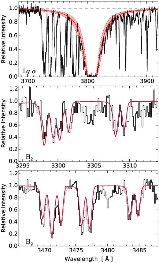
In the top panel, the Ly α transition is shown. The best-fitting Voigt profile is shown in solid red with 3σ range indicated by the red shaded area. In the middle and lower panels, a zoom-in around some of the available H2 lines is shown. The red line marks the best-fitting model to the ro-vibrational lines.
We detected metal absorption lines from various ionization states, ranging from neutral species (C i, Cl i) to highly ionized transitions (C iv, Si iv). The full list of absorption lines detected and their equivalent widths are given in Table A1 of the Appendix A. In order to obtain the column densities for the low-ionization lines, we fitted the weak unsaturated lines using Voigt profiles. We used the iron and manganese lines (Fe iiλ2374 and Mn iiλ2576) with high signal-to-noise ratios to obtain a solution for the number of velocity components, their relative velocities, and their broadening parameters. The best-fitting solution to these lines gave 10 components ranging from v = −183 to +214 km s−1 relative to the strongest absorption component, zsys = 2.132 49. The relative velocities and broadening parameters of the individual components are given in Table 2 for reference. We assumed the broadening to be purely turbulent. This velocity structure was then kept fixed and all lines were fitted simultaneously to infer their column densities. We included the uncertainty on the continuum normalization in the fitting. The best-fitting column densities are reported in Table 2, and the best-fitting line profiles are shown in Fig. 2. The neutral magnesium transition Mg i λ2852 was included in order to constrain the contribution from Mg in the line blend of Zn, Cr, and Mg at 2026 Å. Since the signal-to-noise for the Mg i line was high, we fitted a separate set of seven components to this line. Because of the different velocity structure of the magnesium line we do not include the individual components in Table 2. We further note that the contribution from Co ii to the line blend is negligible due to the weak strength of this transition and the non-detection of other Co transitions, see Table A1. For lines with lower signal-to-noise ratios, we were not able to constrain all 10 components. These unconstrained components are marked with ‘–’ in Table 2. The total abundances from the fit and the calculated metallicities are given in Table 3. We observe a relatively low [S/Zn] ratio of −0.31; this is lower than the average DLA, however not uncommon given the large uncertainty regarding this element (Rafelski et al. 2012; Berg et al. 2015). Furthermore, the abundance of sulphur may be underestimated due to hidden saturation given the lower resolution in the UVB arm. For a resolution of |$\mathcal {R}=6000$|, we find that absorption lines with a flux residual at peak absorption of less than roughly 0.75 are potentially affected by hidden saturation. One of the S ii lines is thus right at the border, but this line is blended with Ly α forest. The other sulphur line is stronger and should therefore be viewed as a lower limit. The hidden saturation might cause the column density to be underestimated by as much as 0.4 dex.
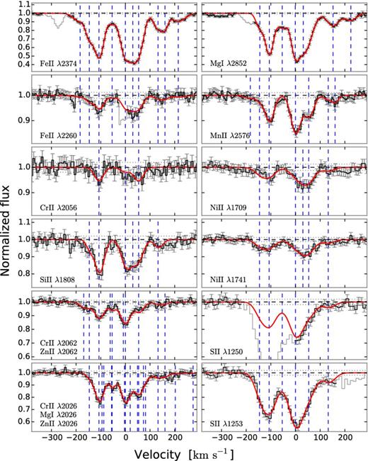
Voigt profile fits to low-ionization lines. The data are shown in black with error bars. Grey areas were excluded in the fits due to blends with other lines. The red line shows the best-fitting model, and the blue dashed lines show the fitted components. Velocities are relative to zsys = 2.132 49.
Column densities for individual components of the Voigt profile fit to eight elements. All entries below are given as log (N/cm−2).
| |$v_{\rm rel}^{a}$| | b | Si ii | S ii | Cr ii | Mn ii | Fe ii | Ni ii | Zn ii |
|---|---|---|---|---|---|---|---|---|
| (km s−1) | (km s−1) | |||||||
| −183 | 32 | – | – | – | 11.49 ± 0.26 | 13.50 ± 0.03 | – | – |
| −146 | 11 | 14.30 ± 0.17 | 14.45 ± 0.07 | – | 11.38 ± 0.25 | 13.69 ± 0.02 | 12.93 ± 0.15 | 11.70 ± 0.15 |
| −107 | 20 | 15.00 ± 0.04 | 14.81 ± 0.04 | 12.65 ± 0.09 | 12.31 ± 0.03 | 14.21 ± 0.01 | 13.22 ± 0.08 | 12.64 ± 0.02 |
| −54 | 10 | – | 14.00 ± 0.19 | – | – | 13.30 ± 0.03 | – | 12.06 ± 0.07 |
| 0 | 22 | 14.90 ± 0.06 | 15.02 ± 0.02 | 12.21 ± 0.27 | 12.50 ± 0.02 | 14.20 ± 0.01 | 13.10 ± 0.16 | 12.68 ± 0.02 |
| 30 | 19 | 14.51 ± 0.20 | – | – | – | 13.93 ± 0.02 | 13.03 ± 0.29 | – |
| 54 | 21 | 14.71 ± 0.11 | 14.52 ± 0.05 | 12.67 ± 0.10 | 12.23 ± 0.04 | 14.12 ± 0.01 | 13.33 ± 0.11 | 12.43 ± 0.03 |
| 133 | 17 | 14.30 ± 0.18 | 14.14 ± 0.10 | – | 11.50 ± 0.20 | 13.62 ± 0.02 | 12.81 ± 0.17 | 11.74 ± 0.16 |
| 161 | 5 | – | – | – | 11.49 ± 0.18 | 13.39 ± 0.03 | – | 11.48 ± 0.24 |
| 214 | 35 | – | – | – | – | 13.52 ± 0.03 | – | – |
aRelative to the systemic redshift zsys = 2.132 49.
Metal abundances from the z = 2.13249 DLA.
| Element (X) | log (NX/cm−2) | [X/H]a |
|---|---|---|
| Si ii, λ1808 | 15.49 ± 0.04 | −0.71 ± 0.07 |
| S ii, λλ1250, 1253 | 15.41 ± 0.02 | −0.40 ± 0.06 |
| Cr ii, λλλ2026, 2056, 2062 | 13.04 ± 0.08 | −1.29 ± 0.09 |
| Mn ii, λ2576 | 12.91 ± 0.02 | −1.21 ± 0.06 |
| Fe ii, λλ2374, 2260 | 14.87 ± 0.01 | −1.32 ± 0.05 |
| Ni ii, λλ1709, 1741 | 13.90 ± 0.07 | −1.01 ± 0.10 |
| Zn ii, λλ2026, 2062 | 13.16 ± 0.02 | −0.09 ± 0.05 |
| C i, λλ1560, 1656 | 13.86 ± 0.04 | – |
| C i* | 13.80 ± 0.04 | – |
| C i** | 12.98 ± 0.11 | – |
| Cl i, λ1347 | 13.34 ± 0.03 | – |
| Mg i, λλ2026, 2852 | 12.93 ± 0.02 | – |
| H2 | 19.4 ± 0.1 | – |
Notes.aWith respect to solar abundances from Asplund et al. (2009).

Apparent optical depth of the Si ii λ1808 line used to calculate ΔV90. In the top panel, we show the cumulative distribution of apparent optical depth. The grey dashed line marks the absorption line centre, and the grey dotted lines mark the 5th and 95th percentiles of this distribution, from which ΔV90 is calculated. The red dashed lines mark the boundaries of the absorption line within which the apparent optical depth distribution is calculated. The boundaries used are −250 and 290 km s−1 with respect to the systemic redshift, zsys = 2.132 49.
3.1 Atomic carbon
We assume a structure for the quasar as follows: the accretion disc around the black hole is responsible for the continuum emission and is assumed to be a point source; the broad emission lines are emitted from a more extended structure of gas called the broad-line region (BLR). In this geometry, an absorption line on top of a continuum region will be unaffected as the cloud covers all of the continuum source. However, an absorption line on top of a broad emission line will absorb the full continuum source but only part of the BLR flux due to the partial coverage of the BLR. Absorption lines on top of broad emission lines will therefore exhibit an LFR depending on the covering fraction of the BLR. An idealized schematic view of the assumed geometry is shown in Fig. 4. The figure shows the case of an absorption line on top of a broad emission line and one in a continuum region only. For clarity, we show saturated lines in the figure, as this allows the LFR to be visualized more easily.
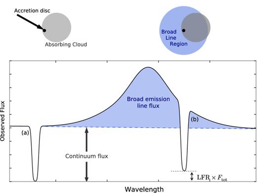
Schematic view of partially absorbing cloud. The top-left panel shows the projected view of the background quasar's accretions disc (black dot) and the foreground absorbing cloud (grey circle). The top-right panel shows the same configuration but with the quasar's BLR shown as the blue circle. Absorption from different transitions in the foreground cloud is seen in the observed spectrum in the lower panel. Here the line marked (a) corresponds to the top-left scenario at a wavelength where there is no contribution from broad emission line flux. The line marked (b) shows the top -right scenario at a wavelength where broad emission line flux is contributing to the total observed flux. Due to the partial coverage of the BLR indicated in the top-right panel, an LFR is observed in the saturated line, i.e. the line does not reach zero.
In the case of gravitational lensing, the LFR for absorption lines in continuum regions and on top of broad emission lines will be identical, since the light from both the central continuum source and the BLR is deflected and reaches the observer unabsorbed. Only in special cases, where the extended BLR is lensed differently from the continuum source, will the LFR be different. We therefore assume that the mismatch observed in the two C i lines is caused by partial coverage due to the absorbing cloud being small in projection compared to the BLR.
Since the C i lines were not saturated, we could not easily measure the LFR as is indicated in Fig. 4. Instead we had to infer the LFR by fitting the absorption lines with various values for the LFR. We defined a grid of discrete value of LFR and for each grid point, we fitted the two absorption line complexes. The likelihood for each grid point was saved and used to fit a polynomial for the likelihood as function of LFR. We then obtained the best-fitting LFR by identifying the maximum likelihood from the polynomial fit, and the uncertainty was given by the curvature of the likelihood function, see the top panel in Fig. 5. The lower panel in Fig. 5 shows the best-fitting C i absorption profile for the two transitions at 1560 and 1656 Å in red. The blue line in the figure shows the fit without taking into account partial coverage. The best fit resulted in an LFR of 16 ± 3 per cent. Fitting the absorption lines for this value of the LFR, we recovered the column densities for C i, C i*, and C i** as given in Table 3.
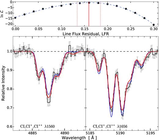
Voigt profile fit to neutral carbon (C i) and its fine structure transitions (C i* and C i**). The thick red line and thin blue line show the best-fitting model with and without partial coverage, respectively. The model without partial coverage poorly estimates the depth of the lines. The top panel shows the likelihood, |$\mathcal {L}$| (normalized to the maximum likelihood) as function of the line flux residual, LFR, for each evaluation in black points. The blue dashed line shows a polynomial fit to the likelihood function. The maximum likelihood estimate (LFR = 0.16 ± 0.03) is shown by the red vertical line with 1σ confidence interval shown by the dotted lines.
In order to recover fcov, we thus need to measure the two quantities Ftot and fcont (since FBLR = Ftot − Fcont) in the spectrum at the wavelength of the C i λ1656 absorption line. The total flux is easy to measure with good precision; however, the continuum flux is more cumbersome as the intrinsic quasar continuum is notoriously difficult to assess. We infer Fcont by interpolating a spline locally in the regions around the C iv emission line (for details see Fig. B1 of the Appendix B). Due to the high level of uncertainty in the continuum evaluation, we assign an error of 10 per cent on the continuum flux. In this way, we obtain Fcont = 22.9 ± 2.3 and Ftot = 29.3 ± 1.5, both in units of 10−16 ergs−1 cm−2 Å−1. Given the best-fitting value of the LFR of 16 ± 3 per cent, the flux measurements result in a covering fraction of the BLR of fcov = 27 ± 6 per cent.
4 DUST EXTINCTION
In Krogager et al. (2015), we assigned the reddening to the quasar itself due to the limited data available. However, in this work we have accurate abundance ratios from the DLA and a much extended wavelength coverage from the X-shooter spectrum. The observed [Fe/Zn] ratio indicates a significant amount of dust in the DLA. First we constrain the dust extinction, A(V), along the line of sight by fitting a quasar template to the observed spectrum. We then compare the best-fitting A(V) to an estimate from the observed depletion ratio of refractory to volatile elements. In the following, we will describe both methods in detail.
4.1 Template fitting
By fitting a quasar template to the spectroscopic data, we were able to model the dust extinction along the line of sight independently from the depletion analysis. We parametrized our model following the method in Krogager et al. (2015). However, we expanded the model to contain a variable intrinsic power-law slope, β, to be able to propagate the correlation between the reddening and the unknown intrinsic slope. In this work, we used the quasar template of Selsing et al. (2015) and fitted for both the intrinsic quasar dust, A(V)QSO, and for dust in the DLA, A(V)DLA. We applied SMC, LMC and LMC2 type extinction curves by Gordon et al. (2003) in the fitting routine, and for the quasar dust we furthermore applied a new extinction curve derived explicitly for quasars (see Zafar et al. 2015, submitted). We fitted the entire spectrum red-wards of Ly α excluding the regions influenced by the broad emission lines and telluric absorption. Furthermore, we used photometric data from WISE band 1 at 3.5 μm. The WISE bands at longer wavelength were not used since the quasar template does not cover these wavelengths. We did not include optical nor NIR photometric data points since all the available photometry was covered by the spectrum. During the initial fit, we noted an apparent mismatch between the template and the data in the spectral range around the C iii] emission line of the quasar. We first suspected this to be caused by the 2175 Å bump feature characteristic of the LMC and LMC2 types of extinction curves. However, neither LMC nor LMC2 extinction curves resulted in better fits. Instead we discovered that the mismatch could be explained by variations in the broad emission from Fe ii and Fe iii, which form a pseudo-continuum in this wavelength range. We used the template of Vestergaard & Wilkes (2001) to model the iron emission. The contributions of Fe ii and Fe iii were separated into two individual templates, and subsequently smoothed to match the observed width of the broad emission lines of the quasar (∼1500 km s−1). By including the variable iron templates, we obtained a much improved fit, see Fig. 6. The best-fitting solution was obtained for the following parameters: |${A(V)_{\rm QSO}}=0.005^{+0.008}_{-0.004}$|, |${A(V)_{\rm DLA}}=0.280^{+0.005}_{-0.009}$|, and β = 0.128 ± 0.007 assuming SMC type dust in the DLA. The results were insensitive to the extinction law in the quasar due to the negligible amount of dust at the redshift of the quasar, also the results were not sensitive to the initial parameter estimate. The best fit was obtained for an excess of Fe ii and a deficit of Fe iii relative to the average quasar template. The errors stated here only represent the statistical errors from the fit. We note that a fit to the data without the parameter A(V)DLA, i.e. with only dust in the quasar, gives an equally good fit. However, from the high level of depletion ([Fe/Zn] = −1.22) we have a strong prior indicating dust in the DLA. Moreover, the presence of neutral carbon (due to its ionization potential of 11.26 eV) requires the cloud to be shielded from the background UV radiation. This leads to a lower photodissociation rate for dust and molecules. The detection of strong H2 absorption thus provides further evidence for dust in the absorbing medium since H2 forms most effectively on the surface of dust grains (e.g. fig. 8 of Noterdaeme et al. 2008).
![The X-shooter spectrum of quasar J 2225+0527 shown in black together with the photometry from SDSS, UKIDSS, and WISE band 1 (shown in yellow squares, the errorbars are too small to be seen). The spectrum in the top panel has been smoothed for presentation purposes. The telluric absorption regions in the NIR (at ∼1.0, 1.1, 1.5, and 1.9 μm) have been masked out. The blue solid curve shows the unreddened quasar template, and the red solid curve shows the same template assuming the best-fitting dust model with iron emission and Ly α absorption included, see Section 4. For reference, the blue dashed line shows the best-fitting dust model without including the iron emission template. The largest offset between the red and the dashed line is observed around the C iii] emission line at ∼ 0.6 μm.](https://oup.silverchair-cdn.com/oup/backfile/Content_public/Journal/mnras/455/3/10.1093_mnras_stv2346/3/m_stv2346fig6.jpeg?Expires=1749885148&Signature=AUHO8OrgceJW-zRE3RPx5gIIVfxqwUS0qVWGz65VdpuIw8gZNR1vk7K6G0wqux~H0Z9Nqz09uFCS1I0Ac7UAwsRenPlXJj-DlSMe4qzED~pgehVQ6BsoreiCtcapKvgVDWxYqqB-VcNAZVXcsL3vRB7Lm58hyzhDFr7QtVoVbuy6jD-oCBC0nitMf4f20RXOUsUd~QVU6DEUfB93auXPlpvTzSDSu0kveRYU7U~m-b8DCxF9C9SBUpS12UalkMPcOUuITdBsE5xvi8aLtLWG4AzvShQq0jUftS6KTfgrACer3wznsbJkkrw27BYkTfjrkQpuyiA886pzehtdqgLOZg__&Key-Pair-Id=APKAIE5G5CRDK6RD3PGA)
The X-shooter spectrum of quasar J 2225+0527 shown in black together with the photometry from SDSS, UKIDSS, and WISE band 1 (shown in yellow squares, the errorbars are too small to be seen). The spectrum in the top panel has been smoothed for presentation purposes. The telluric absorption regions in the NIR (at ∼1.0, 1.1, 1.5, and 1.9 μm) have been masked out. The blue solid curve shows the unreddened quasar template, and the red solid curve shows the same template assuming the best-fitting dust model with iron emission and Ly α absorption included, see Section 4. For reference, the blue dashed line shows the best-fitting dust model without including the iron emission template. The largest offset between the red and the dashed line is observed around the C iii] emission line at ∼ 0.6 μm.
The extinction derived from the fit is strongly correlated with the intrinsic slope of the quasar power law; this introduces a large systematic uncertainty, since we do not a priori know the intrinsic quasar slope. Previous studies have shown the intrinsic slope of quasars to be normally distributed with a width of ∼0.2 (Vanden Berk et al. 2001, but see also Krawczyk et al. 2015; Selsing et al. 2015). By propagating this intrinsic uncertainty on the slope in our fitting, we can estimate the systematic effect on A(V)DLA. A steeper intrinsic slope (smaller β) yields a larger extinction. The change in extinction varies approximately as a linear trend with the slope as ΔA(V)DLA = −0.07 × (Δβ/0.02), where ΔA(V)DLA and Δβ denote the change in best-fitting extinction and slope, respectively. We can include this as a systematic uncertainty in our result: A(V)DLA = 0.28 ± 0.01|stat ± 0.07|sys. We note, that in cases of very shallow slopes the extinction becomes very small and these models prefer dust in the quasar. However, such solutions are inconsistent with the broad-band data from WISE at 3.5 μm and the measure of extinction from the depletion ratio of metal lines in the DLA, see above. Furthermore, the very high luminosity of the quasar (among the top 0.1 per cent brightest quasars at this redshift, λLK = 7.9 × 1046 erg s−1) renders such models highly unlikely as bright quasars typically have steeper slopes (Davis, Woo & Blaes 2007), which would increase our best-fitting value for A(V)DLA.
4.2 Depletion of iron relative to zinc
Following Vladilo et al. (2006) and De Cia et al. (2013), we calculated the column density of iron in the dust phase, |$\log (\hat{N}_{\rm Fe})$|. This quantity is expected theoretically to correlate with A(V), and we used the empirical relation from Vladilo et al. (2006) to calculate A(V)DLA assuming that the intrinsic abundance ratio of (Fe/Zn) is solar. Although zinc is usually assumed to be depleted very little on to dust grains, and as such a good estimator of the volatile elements, this is not the case for high-metallicity systems. For around solar metallicity and above, even zinc may show signs of weak depletion (Vladilo et al. 2006). In order to correct for this differential depletion of both iron and zinc, we assumed that the depletion of iron and zinc follows that of the ISM in the Milky Way, see De Cia et al. (2013). Given the high metallicity ([Zn/H] = −0.09) inferred from zinc, both the solar intrinsic abundance ratio and the Galactic depletion pattern are valid assumptions. We measured a high depletion of [Fe/Zn] = −1.22 ± 0.06, from which we inferred an amount of dust extinction of |${ A(V)} =0.39^{+0.13}_{-0.10}$| mag. We note that neglecting differential depletion of zinc relative to iron for such high metallicities would underestimate A(V) by 0.11 mag. The intrinsic ratio of [Zn/Fe] has been studied extensively (for a recent study, see Berg et al. 2015), and a large spread is generally observed. Berg et al. (2015) show that the intrinsic [Zn/Fe] ratio is most probably lower than solar. This would lead to a higher A(V) in this case. Even with a higher than solar intrinsic ratio of [Zn/Fe] (+0.2 dex), the high level of depletion observed in this DLA requires a significant amount of dust in order to reconcile the observed zinc-to-iron ratio with the intrinsic ratio.
5 THE DLA GALAXY COUNTERPART
In order to identify the galaxy associated with the DLA we have searched for stellar continuum emission in broad-band imaging as well as nebular emission lines in the X-shooter spectrum. However, the bright background quasar impedes detection of the faint glow from the DLA galaxy, and it is therefore necessary to subtract as much of the quasar's light as possible. The method utilized for this subtraction is described below for each data set.
5.1 Optical imaging
For the broad-band images, we had to replicate the PSF in order to subtract the point-like quasar emission. In the NOT r′-band image, we modelled the PSF by combining bright, though not saturated, stars in the field. The light from the quasar was then subtracted using this empirical PSF. In this way, we could probe the regions closer to the quasar. However, the central part (within 0.9 arcsec) was still not accessible due to strong residuals from the PSF subtraction. The PSF subtracted r′-band image is shown in Fig. 7. In the residual image, we observed no emission consistent with that of a DLA galaxy. However, when smoothing the image with a Gaussian filter we detect a fuzzy blob of emission around 4 arcsec south-west of the quasar. This extended emission is consistent with the Ly α nebula observed by Heckman et al. (1991), and moreover is located at the same spatial position as the extended radio lobes reported by Barthel et al. (1988). We therefore ascribe this extended emission to the C iii line of the Ly α nebula, rather than emission from the DLA galaxy. Hence, the DLA galaxy remains undetected down to a limit of mAB > 24.79 mag (3σ limit). Since we were not able to probe the region closest to the quasar, we used apertures placed around the quasar at a distance of 19 arcsec from the quasar to estimate the flux limit. This corresponds to a physical separation of 16 kpc at the redshift of the DLA. The observed r′-band probes flux at ∼1900 Å in the rest frame of the DLA galaxy. This part of the UV continuum is sensitive to recent star formation, and the flux limit thus allows us to constrain the star formation rate using Kennicutt (1998). First we applied a correction for Galactic extinction of |$A_{r^{\prime }}=0.347$| from the maps of Schlafly & Finkbeiner (2011), and converted the corrected flux to a luminosity given the luminosity distance for z = 2.13. Finally, we converted the luminosity to star formation rate (using Chabrier initial mass function, IMF) correcting for dust in the DLA assuming an extinction of 1.5 mag at rest frame 1900 Å. In this way, we obtained a 3σ limit on star formation rate of SFR < 21M⊙ yr−1, under the assumption that the impact parameter is more than 16 kpc. For smaller impact parameters, the star formation rate may be even higher.
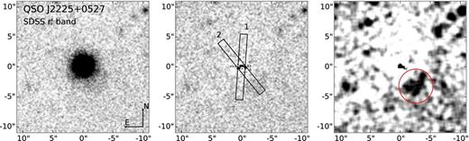
r′-band image from the NOT of the quasar J 2225+0527. The three panels show (left to right) the combined image, the residuals after subtraction of the PSF, and the residual image smoothed by a (5×5 pixel2) Gaussian filter with σfilter = 2 pixels. In the middle panel, the two slit positions used for the X-shooter observations are shown as rectangles. In the right-hand panel, an extended excess of emission is visible about 4 arcsec south-west of the quasar (marked by a red circle).
5.2 NIR imaging
Due to the lack of suitable PSF stars in the small field of view of the Keck AO images we used the quasar itself to make an azimuthally averaged radial PSF profile. We then generated a spherically symmetric PSF from the average radial profile for each image and subtracted the model PSF from the images. In the H and K′ images, we observed a small excess flux at roughly 0.5 arcsec south of the quasar's centroid, see Fig. 8. The emission was observed at the same location in the two images, which is not expected for a random excess due to a spurious peak in the residuals. We thus regarded this as a tentative detection of the DLA galaxy counterpart. We extracted the flux from the small excess by fitting a two-dimensional Gaussian model to the excess emission. By using the measured flux of the quasar in UKIDSS photometry as reference, we obtained the following magnitudes for the tentative DLA counterpart: H = 23.6 and K′ = 23.8 mag, both on the AB system. The PSF in the J-band image was less symmetric than in the other two AO images. This made the PSF modelling more difficult to perform; As a result, we did not obtain a good subtraction of the PSF and no excess emission was observed in the J-band at the same position.
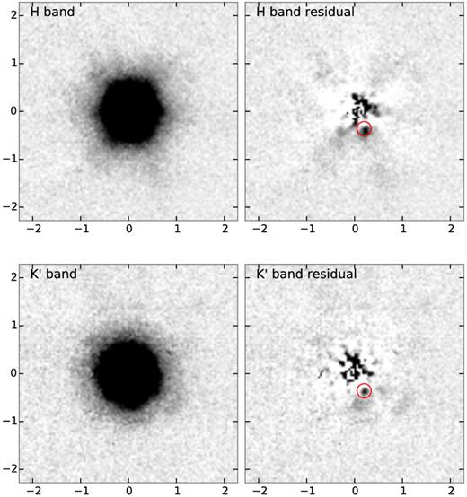
Keck AO images of the quasar J 2225+0527 in the H and K′ bands. The left-hand and right-hand panels in each row show, respectively, the image before and after subtraction of a model PSF (see text). Each image is oriented north to the top and east to the left. The red circle in each residual image marks the location of the tentative detection of the emission counterpart of the DLA at redshift z = 2.13. The radial structure observed in the H-band residuals is an artefact of the circular averaging of the PSF. The J-band image did not result in a successful PSF subtraction and is therefore not shown.
5.3 X-shooter spectroscopy
In order to detect weak nebular emission lines from the DLA galaxy in the spectrum, we subtracted the quasar trace from the two-dimensional spectrum following the method in Krogager et al. (2013). We did not detect any emission from the nebular lines Hα, Hβ, or [O iii] at the redshift of the DLA in our X-shooter spectrum. We obtained flux limits for [O iii] λ5007 and Hα of |$F_{\rm O\, {\small {III}}} < 5.3 \times 10^{-17}\,{\rm erg\, s^{-1}\, cm^{-2}}$| (3σ) and FH α < 16.5 × 10⁻¹⁷ erg s−1 cm−2, respectively. The spatial extent of the aperture used for the flux limit estimation was determined from the width of the spectral trace (FWHM = 5 pixels at the location of H α). We used an aperture size of twice the FWHM (1.5 arcsec) centred on the position of the quasar. In the spectral direction, we used the velocity width of the absorption lines (330 km s−1) centred around the absorption systemic redshift zsys = 2.132489. This provides a conservative upper limit which takes into account the fact that we do not know the exact emission redshift; however, the emission redshift is probably within the velocity spread observed in the different absorption components. Also, we assumed that the emission is at very small impact parameter, which seems plausible given the hints from the Keck imaging described above. Unfortunately, the H α line is located in a region of telluric absorption lines. The flux limit is therefore not very constraining; However, it still allows us to put a limit on the star formation rate by using the relation from Kennicutt (1998). This yields an upper limit on the star formation rate of SFRHα < 29 M⊙ yr−1, assuming Chabrier IMF and correcting for dust.
6 DISCUSSION
The quasar observed in this work, although identified in previous radio catalogues, was missing in the SDSS quasar data base due to significant amounts of dust causing the optical colours of the quasar to appear stellar-like in the SDSS colour spaces. However, since the quasar is a radio-loud quasar it would be expected to appear in the SDSS data base. The reason why this quasar does not appear in SDSS is that the cross matching of SDSS and the FIRST radio catalogue was performed in 2008, whereas Q2225+0527 was not observed until 2009. It is thus an unfortunate coincidence of various factors that resulted in the misclassification of Q2225+0527 in the SDSS data base.
The foreground DLA at z = 2.13 was first reported by Barthel et al. (1990) and later by Junkkarinen, Hewitt & Burbidge (1991) and Ryabinkov, Kaminker & Varshalovich (2003); However, the dust reddening towards the quasar has so far not been studied in detail. Based on the detection of C i and H2 together with high depletion from [Zn/Fe], we had strong evidence for dust in the DLA. This was further bolstered by our spectral fitting. The best-fitting model had all the dust in the DLA. We found the DLA to be of solar metallicity with [Zn/H] = −0.09 ± 0.05 and we inferred a dust-to-gas ratio of |${ A(V)}/N({\rm H\, {\small {I}}}) = 5.5\times 10^{-22}\,{\rm mag\,cm^2}$| consistent with that of the local ISM (4–6 × 10⁻²² mag cm2; Liszt 2014). This value of dust-to-gas ratio is much higher than the average DLA (|${ A(V)}/N({\rm H\,{\small {I}}}) = 2\text{-}4\times 10^{-23}\,{\rm mag\,cm^2}$|; Vladilo, Prochaska & Wolfe 2008).
This shows that dusty DLAs indeed do exist and that they are, to some degree, missed in optically selected quasar samples. The quasar studied here is intrinsically very bright and red (among the top 0.1 per cent most luminous and top 1 per cent most red quasars at these redshifts, see Figs 9 and 10). A bias against dusty DLAs, and absorption systems in general, is therefore not only limited to the faint end of the quasar luminosity function. The bright quasars are also affected due to the reddening caused by dust allowing the quasars to escape detection by optical colour criteria. The actual colour criteria used by SDSS are hard to visualize, since the algorithm works in a multidimensional colour space (Richards et al. 2002). However, in order to visualize the effect of dust reddening we show the u − g and g − r colour–colour diagram in Fig. 10. The contours and small blue points indicate SDSS quasars, showing that they mostly cluster in the region around (0, 0). The individual points at redder colours are added to the SDSS sample by various other criteria such as radio selection (for comparison, see Richards et al. 2001, 2002). The red dot marks the observed colours of the quasar in this work and its intrinsic colours after correcting for the DLA dust (the red square connected to the red dot by a line). The quasar thus falls in the region of optically selected quasars if there had been no dust in the DLA. Owing to its very bright radio emission, the quasar presented here was identified in radio surveys. However, only about 10 per cent of quasars are radio loud (Baloković et al. 2012). Hence, more dusty absorbers might be missing towards red, radio-quiet quasars. The DLA presented here is similar to the recent sample of neutral carbon absorbers by Ledoux et al. (2015) both in terms of C i abundance and dust extinction. These authors also argue that the most dusty absorption systems are missing in current samples selected using optical criteria.
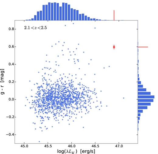
Distribution of SDSS g − r colour and the K-band luminosity for quasars with redshifts from 2.1 < z < 2.5 (blue points and histograms) selected from the sample of Peth, Ross & Schneider (2011). The quasar presented in this work is shown in red. All magnitudes have been corrected for Galactic extinction of E(B − V) = 0.132.
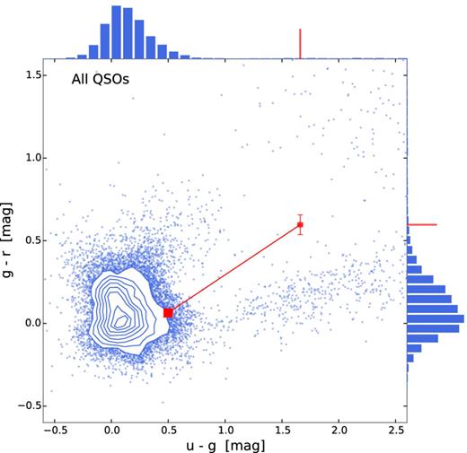
Distribution of SDSS u − g and g − r colours for quasars (blue contours and points) selected from the sample of Peth et al. (2011). The red dot marks the observed colours of the quasar, Q2225, presented in this work. The red square connected to the red dot by the line marks the colours of Q2225 after correcting for the foreground reddening from the DLA. The intrinsic colours of the quasar are thus consistent with the bulk of quasars identified in SDSS, though slightly redder than the average. This is consistent with the redder than average intrinsic slope inferred from the spectral fitting. All magnitudes have been corrected for Galactic extinction of E(B − V) = 0.132.
The impact of this bias, i.e. the frequency of dusty DLAs, is not a large effect when seen in terms of the overall number of DLAs. The criteria used in the HAQ survey (Krogager et al. 2015) select around 2 per cent of the general quasar population (known in SDSS Data Release 10). Of the quasars identified in the HAQ survey, about 2 per cent have dusty foreground absorbers. Hence, only a small number of absorbers are missed. However, these absorbers are primarily metal-rich and will contribute to a significantly larger fraction of the metals, since the bulk of DLAs have very low metallicities. This is consistent with what has been found in radio surveys of DLAs (Ellison et al. 2001; Jorgenson et al. 2006), i.e. dust biasing does not have a strong effect on the bulk of the DLA population. We furthermore caution the reader that the numbers presented here are only rough approximations and a more detailed investigation of the selection effects is still needed.
6.1 Partial coverage and size of the BLR
In Section 3.1, we derived the LFR from the C i absorption lines. If we interpret the LFR as a geometric effect caused by partial coverage of the background emitting source (in this case the BLR of C iv) then the LFR can be converted to a covering fraction. Other explanations for the LFR would be gravitational lensing of the quasar or a double quasar, see the discussion in Balashev et al. (2011). As argued in Section 3.1 we favour the geometric effect since the other scenarios require a somewhat unlikely conspiracy of alignments. However, with the current data, we cannot exclude the other scenarios and we caution the reader that the following exercise is merely suggestive.
Given the covering fraction of 27±6 per cent of the BLR, inferred in Section 3.1, we can calculate the size of the BLR assuming a simple spherical geometry of both the absorbing cloud and the BLR, as depicted in the schematic view of Fig. 4. A prerequisite for this calculation is the physical size of the absorbing cloud, which we can estimate from the fine-structure levels of C i. These fine-structure levels are excited by the background radiation field and by collisions with other species predominantly hydrogen (both atomic and molecular). The population of the various levels will therefore depend on the density and temperature of the gas. In the following, we assume that neutral carbon arises from the cold self-shielding cloud where molecular hydrogen is the primary collisional partner. We then use the numerical code popratio (Silva & Viegas 2001) to calculate the population of various fine-structure levels for a grid of temperatures (50–500 K) and densities (1–1000 cm−3). Assuming that the column densities derived in Sect. 3.1 trace the physical densities, i.e. |$N({\rm C}\, \small {I})/N({\rm C}\, \small {I}^{*})=n({\rm C}\, \small {I})/n({\rm C}\, \small {I}^{*})$|, we can then calculate the allowed range in temperature and density (|$n_{\rm H_2}$|). The temperature and density are highly degenerate and the temperature remains unconstrained, though typical values for the cold, neutral phase lie in the range of 50–200 K. However, we obtain a range of allowed densities from 90 to 400 cm−3 with a most probable density around 100 cm−3 for T = 100 K.
With the physical density of H2 at hand, we can infer a physical length-scale of the small absorbing cloud from the ratio of column density to volumetric density: lcloud = N/n ≈ 0.1 pc. We assume that the cloud is spherically symmetric with radius rcloud = lcloud/2. In projection as shown in the top-right panel of Fig. 4, the system will therefore appear like two overlapping discs with an offset between the two centres, Δl. Since we do not know this projected separation we calculate a grid of various separations and radii of the BLR. For each grid point, we can then evaluate the covering fraction of the BLR by the small cloud of radius rcloud = 0.05 pc. Since the quasar and absorbing cloud are independent the projected separation between the centres of the two discs will be randomly distributed. For the spherically symmetric geometry that we assume, the probability of a given Δl will depend linearly on the separation p(Δl) ∝ Δl, i.e. there is zero probability of a perfect alignment. We furthermore require Δl ≤ rcloud since the continuum source (the accretion disc) in the centre of the BLR must be covered by the absorbing cloud. These two requirements serve as our prior on the separation: |$p(\Delta l) = 2\Delta l/r_{\rm cloud}^2$| for Δl ≤ rcloud and p(Δl) = 0 for Δl > rcloud. Given the measurement of the covering fraction we can convert the two-dimensional grid of covering fraction as a function of RBLR and Δl to a likelihood function. By multiplying the likelihood function with the prior on Δl and marginalizing over all separations, we obtain the most probable radius of the C iv BLR, RBLR = 0.1 pc. However, given the large uncertainties on the density, temperature, and size of the cloud, the size of the BLR is not constrained to better than a factor of ∼2, i.e. RBLR ≈ 0.05–0.2 pc.
From the observed correlation between the physical size of the BLR and luminosity, we can independently estimate the radius of the BLR. We use the relation for C iv from Kaspi et al. (2007), who quantify the relation in terms of the luminosity at 1350 Å. In the X-shooter spectrum, we measure λLλ(1350) = 3.48 × 1046 erg s−1, which corresponds to RBLR = 0.17 pc with an uncertainty of 54 per cent dominated by the scatter in their calibration. This is well within the uncertainties on both the radius–luminosity relation and our estimate. The good agreement between the two size estimates provides evidence for the partial coverage due to the small projected size of the cloud compared to the BLR, despite the simple geometry we assumed.
6.2 Stellar mass of the DLA galaxy
The velocity structure of the absorbing gas contains 10 individual components spread over a total range of 397 km s−1. Such a wide span of velocities is in fact quite common for absorbers with a similar high metallicity (Ledoux et al. 2006), and it is believed to be related to the deep potential well of the massive dark matter haloes that host high-metallicity galaxies (Møller et al. 2013; Neeleman et al. 2013; Arabsalmani et al. 2015). In Section 3, we quantified the velocity width of the system using ΔV90 for which we obtain a value of 331 km s−1. The resolution of X-shooter at the observed wavelength of the line is 27.2 km s−1, and we use the method described by Arabsalmani et al. (2015) to correct the ΔV90 measured and obtain the intrinsic value ΔV90 = 329 km s−1.
The ΔV90 has been shown to correlate with metallicity, a correlation which depends on the redshift (Ledoux et al. 2006). The evolution of the zero-point of the relation is shown in Fig. 11 (black points and full red line from Møller et al. 2013). The 1σ of the intrinsic scatter of the relation is marked by the dashed red lines, and the DLA (blue star) is seen to lie well within this scatter. Christensen et al. (2014) confirmed the expectation that the relation in reality is a mass–metallicity relation, and using the prescription from Christensen et al. (2014), and [M/H] = −0.1, we predict a stellar mass of log (M⋆/M⊙) = 10.78 ± 0.55 which is among the few most massive DLA galaxies known at any redshift. We note that because we do not know the impact parameter for this galaxy we use the average value 0.44 for C[M/H]. In case the true impact parameter is very small, C[M/H] would be somewhat smaller and likewise then the stellar mass (as discussed below).
![Comparison to the redshift evolution of the global metallicity–ΔV90 relation of DLAs. The quantity [M/H]$_{\rm 100\,km s^{-1}}$ denotes the metallicity normalization of the relation at 100 km s−1. Black dots and full red line mark the binned data and simple linear fit, red dashed lines mark the 1σ internal scatter of the relation from Møller et al. (2013). DLA-2225+0527 is seen to lie well within the general distribution of intervening DLAs.](https://oup.silverchair-cdn.com/oup/backfile/Content_public/Journal/mnras/455/3/10.1093_mnras_stv2346/3/m_stv2346fig11.jpeg?Expires=1749885148&Signature=bw1AqPzjMxOHsneVq2TAkqjDyGPJNbvFUZ5t23zhSbhQVpRaXgR7PleCM3FKKG28ArEg2GejGLvPETbINZFqDo8gJ4H7Dv3SPPzVkVv6jQMGS-eWcuLZ10VeS-nl0KPfUc0mXNc4DtiBjoRTfRyVOaAXYF~CpXIWPSqKcr~jnuZnTgS4TNMDOWxEjdgSINmFbn97xewyh1QACOeT2-mfA-AGGmLtGUdouEnujBtqNe8xthfTn94YfCr-jKbCTzknzqlDSdTkvqfl1TDvkBGhT0T-8iiiIooJM7Qhy~tjDaRCQ2jiNFCTmdQmVMlBnAAD1diXianawPavKyhOOR5lZA__&Key-Pair-Id=APKAIE5G5CRDK6RD3PGA)
Comparison to the redshift evolution of the global metallicity–ΔV90 relation of DLAs. The quantity [M/H]|$_{\rm 100\,km s^{-1}}$| denotes the metallicity normalization of the relation at 100 km s−1. Black dots and full red line mark the binned data and simple linear fit, red dashed lines mark the 1σ internal scatter of the relation from Møller et al. (2013). DLA-2225+0527 is seen to lie well within the general distribution of intervening DLAs.
Comparing to the three known DLA galaxies at similar redshifts (Christensen et al. 2014, tables 2 and 3), those have masses computed from the same formula in the range log (M⋆/M⊙) = 9.9–11.0, and rest-frame optical AB magnitudes of 23.6, 24.4, and 25.2. In case we assume that the DLA galaxy in our case is perfectly aligned with the quasar (i.e. impact parameter of zero) then we can use equation 3 from Christensen et al. and obtain the lowest possible stellar mass of log (M⋆/M⊙) = 10.00. This is still a very high stellar mass for a DLA galaxy, but the galaxy would remain hidden under the glare of the quasar.
We searched for the emission counterpart of the DLA both in the X-shooter spectrum and in imaging. From the spectrum we only obtained upper limits on the [O iii] and H α line fluxes, and the r′-band image only provided a flux limit for impact parameters larger than 16 kpc. Interestingly, we observed tentative signs of the emission counterpart in the NIR AO images in the H and K′ bands. Although this is highly uncertain given the relatively simple PSF subtraction, it is however reassuring that the excess emission is observed at the same spatial location in the two images. We can thus speculate that the DLA is associated with the excess emission observed in the NIR images at an impact parameter of roughly 4 kpc. The inferred H-band magnitude of the emission counterpart would then be 23.6 mag which is in good agreement with the observed fluxes in the sample of Christensen et al. (2014). In previous studies of emission counterparts of DLAs, we inferred star formation rates of 13 and 27 M⊙ yr−1 (Fynbo et al. 2013b; Krogager et al. 2013) for DLAs with slightly lower metallicities of [Zn/H] ≈ −0.5. The upper limit on the star formation rate of SFR < 29 M⊙ yr−1 derived in Section 5 is therefore consistent with previous detections.
7 SUMMARY
In this work, we presented imaging and spectroscopic observations of the quasar J 2225+0527 and found that the DLA at z = 2.13 has high metallicity (consistent with solar), high level of depletion (inferred from [Fe/Zn]), and strong molecular hydrogen absorption. Moreover, we detected neutral carbon absorption lines showing signs of partial coverage due to the projected size of the absorbing cloud being small compared to the background source. By deriving the covering fraction and a rough size estimate of the absorbing cloud, we were able to infer the size of the BLR of C iv in the quasar to be 0.05–0.2 pc. This is consistent with the estimate from the radius–luminosity relation from Kaspi et al. (2007) to within the 1σ scatter of 54 per cent of their relation.
From the depletion ratio, we estimated the amount of dust in the DLA to be |$A(V)=0.39^{+0.13}_{-0.10}$| mag. Spectral modelling of the quasar resulted in a best-fitting A(V) of A(V)DLA = 0.28 mag with no dust in the quasar itself. We therefore concluded that the reddening of the quasar is caused by dust located in the DLA, and that this reddening caused the quasar to be misclassified as a star in SDSS.
We observed tentative evidence for an emission counterpart to the DLA in the NIR H- and K′-band images at an impact parameter of roughly 0.5 arcsec or 4 kpc. The flux of the tentative DLA galaxy in the H band was estimated to be roughly 23.6 AB mag. This corresponds to a stellar mass of roughly 109–1010 M⊙ consistent with the estimate from the mass–metallicity relation of Christensen et al. (2014).
The quasar studied in this work, although identified previously in radio surveys, was misidentified as a star in SDSS due to several factors. Had this been a more typical quasar in terms radio loudness, the quasar would have been missed by the optical criteria utilized by SDSS and furthermore missed by radio surveys. Therefore, enriched and dusty galaxies detected in absorption towards quasars are under-represented in the current optically selected samples. This has important implications for the mapping of chemical enrichment, as it introduces a bias against the most enriched systems at high redshift. Although this bias only introduces a small effect in terms of the number of missing absorbers, the impact of the bias on the metallicity distribution as well as the cold gas fraction still needs to be determined quantitatively.
This study is based on observations made with the Nordic Optical Telescope, operated by the Nordic Optical Telescope Scientific Association at the Observatorio del Roque de los Muchachos, La Palma, Spain, of the Instituto de Astrofísica de Canarias, and on Very Large Telescope observations carried out at the European Organization for Astronomical Research in the Southern hemisphere, Chile under DDT programme 293.A-5033. Some of the data presented herein were obtained at the W.M. Keck Observatory, which is operated as a scientific partnership among the California Institute of Technology, the University of California and the National Aeronautics and Space Administration. The Observatory was made possible by the generous financial support of the W.M. Keck Foundation.We thank Marianne Vestergaard for insightful discussion and for sharing her iron emission template with us. We thank the ESO Director General for allocating our observing program under the director's discretionary time. The Dark Cosmology Centre is funded by the DNRF. The research leading to these results has received funding from the European Research Council under the European Union's Seventh Framework Program (FP7/2007-2013)/ERC Grant agreement no. EGGS-278202. This research has made use of the Keck Observatory Archive (KOA), which is operated by the W. M. Keck Observatory and the NASA Exoplanet Science Institute (NExScI), under contract with the National Aeronautics and Space Administration.
Interestingly, this target, although not classified as such in SDSS, is a well-known radio source discovered by Gower, Scott & Wills (1967) and identified as 4C 05.84. The QSO was later spectroscopically observed and a redshift of z = 2.323 was measured (Barthel, Tytler & Thomson 1990). Barthel et al. also identified the zabs = 2.132 DLA. However, this did not come to our attention before starting the follow-up observations. The previous low-resolution data were also not adequate for the detailed absorption line analysis in this work.
REFERENCES
APPENDIX A: ABSORPTION LINES
The full list of identified absorption lines belonging to the DLA is given in Table A1. We further quote the equivalent widths for each line.
List of absorption lines from the z = 2.132 49 DLA.
| Transition | EWa |
|---|---|
| Fe ii,λ1144 | 0.623 ± 0.009 |
| S ii,λ1250b | <0.392 ± 0.007 |
| S ii,λ1253 | 0.339 ± 0.005 |
| S ii,λ1259 + Si ii + Fe ii,λ1260 | 2.294 ± 0.006 |
| O i,λ1302 + Si ii,λ1304 | 3.157 ± 0.004 |
| C ii,λ1334 + C ii*, λ1335 | 2.243 ± 0.006 |
| Ni ii,λ1370 | 0.105 ± 0.005 |
| Ni ii,λ1454 | 0.045 ± 0.004 |
| Al ii,λ1670 | 1.967 ± 0.004 |
| Ni ii,λ1709 | 0.074 ± 0.005 |
| Ni ii,λ1741 | 0.119 ± 0.004 |
| Si ii,λ1526 | 1.662 ± 0.006 |
| Fe ii,λ1608 | 0.754 ± 0.004 |
| Si ii,λ1808 | 0.184 ± 0.008 |
| Co ii,λ1941 | <0.018 (3σ) |
| Co ii,λ2012b | <0.04 ± 0.02 |
| Mg i + Zn ii,λ2026 | 0.276 ± 0.006 |
| Cr ii,λ2056 | 0.055 ± 0.007 |
| Cr ii + Zn ii,λ2062 | 0.137 ± 0.006 |
| Fe ii,λ2249 | 0.042 ± 0.005 |
| Fe ii,λ2260 | 0.086 ± 0.005 |
| Fe ii,λ2344 | 1.899 ± 0.005 |
| Fe ii,λ2374 | 0.946 ± 0.004 |
| Fe ii,λ2382 | 2.682 ± 0.003 |
| Mn ii,λ2576 | 0.160 ± 0.004 |
| Fe ii,λ2586 | 1.741 ± 0.004 |
| Mn ii,λ2594 | 0.144 ± 0.004 |
| Fe ii,λ2600b | 2.973 ± 0.003 |
| Mn ii,λ2606b | 0.278 ± 0.003 |
| Mg ii,λ2796 | 4.759 ± 0.005 |
| Mg ii,λ2803 | 4.350 ± 0.005 |
| Mg i,λ2852 | 0.909 ± 0.005 |
| Cl i,λ1347 | 0.060 ± 0.005 |
| C i + C i* + C i,**λ1328 | 0.231 ± 0.004 |
| C i + C i* + C i,**λ1560 | 0.216 ± 0.004 |
| C i + C i* + C i,**λ1656 | 0.390 ± 0.003 |
| N i,λ1199 + N i,λ1200 | 2.228 ± 0.010 |
| N i,λ1134.4 | 1.451 ± 0.009 |
| C iv,λ1550, 1548 | 2.924 ± 0.007 |
| Al iii,λ1854 | 0.559 ± 0.009 |
| Al iii,λ1862 | 0.392 ± 0.009 |
| Si iv,λ1393 | 1.041 ± 0.006 |
| Si iv,λ1402 | 0.645 ± 0.006 |
Notes.aRest-frame equivalent width in units of Å.
bContaminated line.
APPENDIX B: CONTINUUM DETERMINATION
The continuum flux of the quasar around the C iv line is obtained by interpolation of relatively emission-line free regions. This is however very uncertain, as many broad and weak lines can blend together, which may create a so-called pseudo-continuum. For this reason we assume a conservative uncertainty of 10 per cent for the placement of the continuum. The estimated continuum is shown in Fig. B1.
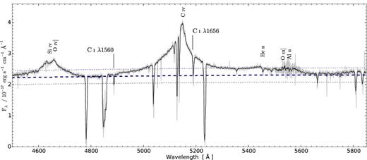
Spectrum of QSO J 2225+0527 around the C iv emission line. The spectrum has been smoothed by a 21 pixel median filter for clarity (the dark grey line). The lighter grey underlying line indicates the spectrum before smoothing. The two absorption line complexes from C i are marked. The estimated quasar continuum is shown by the dashed line. The conservative uncertainty of 10 per cent is shown by the dotted lines. The vertical labels indicate the strongest emission lines from the quasar.
