-
PDF
- Split View
-
Views
-
Cite
Cite
R. Taverna, R. Turolla, D. Gonzalez Caniulef, S. Zane, F. Muleri, P. Soffitta, Polarization of neutron star surface emission: a systematic analysis, Monthly Notices of the Royal Astronomical Society, Volume 454, Issue 3, 11 December 2015, Pages 3254–3266, https://doi.org/10.1093/mnras/stv2168
Close - Share Icon Share
Abstract
New-generation X-ray polarimeters currently under development promise to open a new window in the study of high-energy astrophysical sources. Among them, neutron stars (NSs) appear particularly suited for polarization measurements. Radiation from the (cooling) surface of an NS is expected to exhibit a large intrinsic polarization degree due to the star strong magnetic field (≈1012–1015 G), which influences the plasma opacity in the outermost stellar layers. The polarization fraction and polarization angle as measured by an instrument, however, do not necessary coincide with the intrinsic ones derived from models of surface emission. This is due to the effects of quantum electrodynamics in the highly magnetized vacuum around the star (the vacuum polarization) coupled with the rotation of the Stokes parameters in the plane perpendicular to the line of sight induced by the non-uniform magnetic field. Here, we revisit the problem and present an efficient method for computing the observed polarization fraction and polarization angle in the case of radiation coming from the entire surface of an NS, accounting for both vacuum polarization and geometrical effects due to the extended emitting region. Our approach is fairly general and is illustrated in the case of blackbody emission from an NS with either a dipolar or a (globally) twisted magnetic field.
1 INTRODUCTION
Polarization measurements of radiation coming from astrophysical sources helped in improving our knowledge about the physical and geometrical properties of a variety of systems, from black holes to gamma-ray bursts (e.g. Trippe 2014, for a review). In this respect, neutron stars (NSs) are among the most promising targets for polarimetry due to their strong magnetic field which is expected to induce a large degree of polarization of the emitted radiation.
Radio and optical polarimetry has been already used to derive the orientation of the magnetic and rotation axes of radio pulsars (Manchester & Taylor 1977; Lyne & Manchester 1988; see also Pavlov & Zavlin 2000). The discovery over the last two decades of new classes of X-ray bright, radio-silent NSs with very faint (if any) optical counterparts (chiefly the magnetar candidates, e.g. Mereghetti 2008; Turolla, Zane & Watts 2015, and the X-ray dim isolated neutron stars, XDINSs, e.g. Turolla 2009; Kaspi 2010) renewed the interest in possible polarization measurements at X-ray energies in NS sources. Despite some efforts were made in the past to measure polarization in the X-rays, mainly with the OSO-8 and INTEGRAL satellites (Weisskopf et al. 1978; Hughes, Long & Novick 1984; Dean et al. 2008; see also Kislat et al. 2015), the poor sensitivity of past instrumentation did not lead to conclusive results. A new window opened in the last years, with the advent of new-generation X-ray polarimeters, like XIPE,1 IXPE and PRAXyS2 (recently selected for the study phase of the ESA M4 and NASA SMEX programmes, respectively), which are based on the photoelectric effect and provide a dramatic increase in sensitivity over an energy range ∼1–30 keV (see Bellazzini et al. 2013). X-ray polarimeters derive polarization observables by detecting a modulation in the azimuthal distribution of events in the focal plane. Actually, while a measure of the circular polarization degree is possible in the optical band (see e.g. Wiktorowicz et al. 2015), current instruments, based on the photoelectric effect or Compton scattering, can only provide information about linear polarization (Fabiani & Muleri 2014).
From a theoretical viewpoint, polarization observables (the polarization fraction and the polarization angle) are conveniently expressed through the Stokes parameters. The comparison between the polarization properties of the photons emitted at the source and those measured at Earth is not straightforward for two main reasons. The first is that the Stokes parameters are defined with respect to a given frame, which is in general different for each photon. When the Stokes parameters relative to the different photons are added together, care must be taken to rotate them, so that they are referred to the same frame, which coincides with the frame in the focal plane of the detector. This effect becomes important every time radiation comes from a spatial region endowed with a non-constant magnetic field, and will be referred to as ‘geometrical effect’ in the following. The second issue, which typically arises in NSs, is related to ‘vacuum polarization’. In the presence of a strong magnetic field, quantum electrodynamics (QED) alters the dielectric and magnetic properties of the vacuum outside the star, substantially affecting polarization (Heyl & Shaviv 2002). Because of this, (100 per cent linearly polarized) photons emitted by the surface will keep their polarization state up to some distance from the star, as they propagate adiabatically. This implies that the degree of polarization and the polarization angle, as measured at infinity, depend also on the extension of the ‘adiabatic region’, which in turn depends on the photon energy and on the magnetic field.
The observed polarization properties of radiation from isolated NSs were investigated in the past both in connection with the emission from the cooling star surface and the reprocessing of photons by magnetospheric electrons through resonant Compton scattering, a mechanism which is thought to operate in magnetars. Pavlov & Zavlin (2000) studied the case of thermal emission from the entire surface of an NS covered by an atmosphere, without accounting for QED and geometrical effects. A quite complete analysis of the observed polarization properties of surface emission from an NS has been presented by Heyl, Shaviv & Lloyd (2003), while Lai & Ho (2003) and van Adelsberg & Perna (2009) focused on the role played by the vacuum resonance,3 which occurs in the dense atmospheric layers, on the polarization, and may provide a direct observational signature of vacuum polarization. The two latter works were restricted to the case of emission from a small hotspot on the NS surface, over which the magnetic field can be treated as uniform, therefore no account for rotation of the Stokes parameters was required. Fernández & Davis (2011) and Taverna et al. (2014) have shown that X-ray polarization measurements can provide independent estimates of the geometrical and physical parameters and probe QED effects in the strong field limit in magnetar sources.
In this paper, we re-examine the problem and present a simplified, efficient method to derive the observed polarization properties of radiation emitted from the entire surface of an NS. Our results are in agreement with those of Heyl et al. (2003) and van Adelsberg & Perna (2009), and our faster approach allows to systematically explore the dependence of the polarization observables on the different geometrical and physical quantities. In particular, we discuss the difference between the polarization properties of the radiation emitted by the star and those measured at Earth, which is induced by geometrical and QED effects. This aspect, which is crucial when one needs to reconstruct the star properties from the observed quantities, has not been systematically investigated in previous works. A complete study based on physically consistent models of surface emission is outside the scope of this analysis, and we just assume a simple model in which the surface emission is a (isotropic) blackbody and the magnetic field is dipolar (or a globally twisted dipole field). The outline of the paper is as follows. The theoretical framework is introduced in Section 2. In Section 3, calculations and results are presented, while Section 4 contains a discussion about our findings and the conclusions.
2 THEORETICAL OVERVIEW
In this section, we briefly summarize some basic results about the evolution of the polarization state of electromagnetic radiation propagating in a strongly magnetized vacuum. Although the considerations we present below are focused on radiation travelling in the surroundings of an NS, they hold quite in general.
2.1 Photon polarization in strong magnetic fields
In the presence of strong magnetic fields photons are linearly polarized in two normal modes: the ordinary mode (O-mode), in which the electric field oscillates in the plane of the propagation vector |$\boldsymbol {k}$| and the local magnetic field |$\boldsymbol {B}$| and the extraordinary mode (X-mode), in which, instead, the electric field oscillates perpendicularly to both |$\boldsymbol {k}$| and |$\boldsymbol {B}$|. This holds for photon energies below the electron cyclotron energy (E < Ece = ℏeB/mec ≃ 11.6(B/1012 G) keV; Gnedin & Pavlov 1974), which implies B ≳ 1011 G at X-ray energies, whereas B can be as low as ∼1010 G in the optical band. Moreover, the polarization state of photons propagating in vacuo is also influenced by the effects of vacuum polarization (Heyl & Shaviv 2000, 2002, Harding & Lai 2006). According to QED, in fact, photons can temporarily convert into virtual e± pairs. The strong magnetic field polarizes the pairs, modifying the dielectric, |$\boldsymbol {\varepsilon }$|, and magnetic permeability, |$\boldsymbol {\mu }$|, tensors of the vacuum, which would coincide with the unit tensor otherwise.
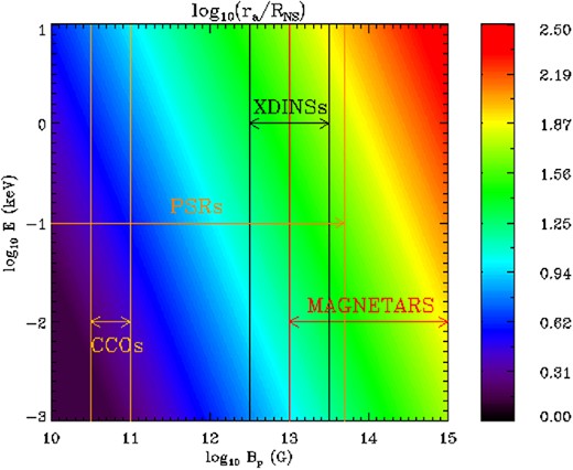
Contour plot showing the adiabatic radius ra (in units of the stellar radius RNS) as a function of the polar magnetic field strength and the photon energy. The typical BP-ranges for different classes of neutron stars, the magnetars, the isolated, thermally emitting NSs (XDINSs), the radio pulsars (PSRs) and the central compact objects (CCOs), are also shown.
2.2 Polarized radiative transfer
In order to measure the polarization properties of a given source, a polarimeter will collect a large number of photons, each characterized by its own set of Stokes parameters. The convenience of using the Stokes parameters lies precisely in the fact that they are additive (e.g. Rybicki & Lightman 2004): the Stokes parameters associated to the whole collected radiation (i.e. the superposition of all the received photons) are equal to the sum of the Stokes parameters of the single photons. However, care must be taken since the quantities in equations (3) are defined with respect to a precise reference frame, (x, y, z), that depends on the direction of the local magnetic field |$\boldsymbol {B}$| (see Section 2.1). As the magnetic field is in general non-uniform across the emission region, its direction at a given point will depend on the source magnetic topology. Since the direction of the electric field of each photon varies very quickly inside the adiabatic region, but it is frozen outside, what actually matters is not the B-field direction at the original emission point, but that at the point where the photon crosses the adiabatic boundary ra, as pointed out by Lai & Ho (2003). Let us call (xi, yi, zi) the reference frame in which the Stokes parameters associated to the generic photon are defined at the adiabatic radius. While the zi-axes are all along the same direction (that coincides with the observer line of sight, LOS), the xi- and yi-axes will point, in general, in different directions for each photon (see Fig. 2).
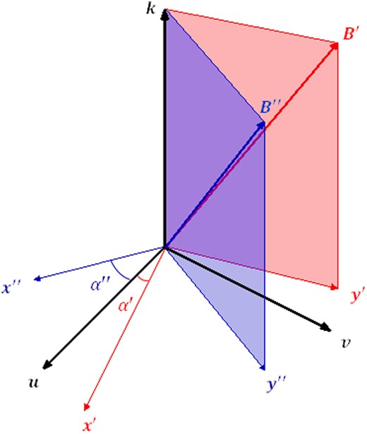
Graphical visualization of the different reference frames introduced in the text. |$\boldsymbol {k}$| is the common direction of propagation (LOS); |$(\boldsymbol {u}$|, |$\boldsymbol {v})$| are the fixed, mutually orthogonal axes of the polarimeter; |$(\boldsymbol {x}^{\prime },\boldsymbol {y}^{\prime })$| and |$(\boldsymbol {x}^{\prime \prime },\boldsymbol {y}^{\prime \prime })$| are mutually orthogonal axes of two reference frames relative to photons coming from points characterized by the directions |$\boldsymbol {B}^{\prime }$| and |$\boldsymbol {B}^{\prime \prime }$| of the magnetic field. The angles α′, α″ are also indicated.
To sum correctly the Stokes parameters, it is necessary to refer them to the same, fixed frame, say (u, v, w). This frame can be chosen in such a way to coincide with that of the polarimeter, with u and v in the detector plane and w along the LOS.
2.3 Polarization observables
3 POLARIZATION OF SURFACE EMISSION FROM NEUTRON STARS
In this section, we present quantitative results for the polarization observables in the case of surface (thermal) emission from an NS endowed with an axially symmetric magnetic field, either a dipole or a (globally) twisted dipole, the latter often used to describe the magnetosphere of magnetars (see Thompson, Lyutikov & Kulkarni 2002).
3.1 The α-distribution
Let us introduce a reference frame (X, Y, Z) with the Z-axis in the direction of the LOS (unit vector |$\boldsymbol {\ell }$|), |$\boldsymbol {X}$| in the plane of |$\boldsymbol {\ell }$| and the star spin axis (unit vector |$\boldsymbol {\Omega }$|) and |$\boldsymbol {Y}=\boldsymbol {\ell }\times \boldsymbol {X}$|. The geometry is shown in Fig. 3(a), where χ is the angle between the spin axis and the LOS, and ξ is the angle between the spin axis and the magnetic dipole axis (unit vector |$\boldsymbol {b}_\mathrm{dip}$|).
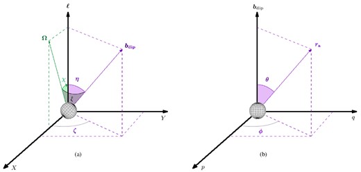
The two reference frames used in the calculation of the α angle. Left: the (X, Y, Z) frame with the Z-axis in the direction of the LOS |$\boldsymbol {\ell }$|, the X-axis in the plane |$\boldsymbol {\ell }$|–|$\boldsymbol {\Omega }$|, where |$\boldsymbol {\Omega }$| is the star spin axis, and the Y-axis perpendicular to both X and Z. Right: the (p, q, t) reference frame with the t-axis along the star magnetic axis |$\boldsymbol {b}_\mathrm{dip}$|, the p and q two mutually orthogonal axes in the plane perpendicular to |$\boldsymbol {b}_\mathrm{dip}$| (see Appendix B for more details). The angles ξ, χ, η, ζ, θ and ϕ are also shown.

The path of a photon emitted by a point on the star surface with polar angles ΘS and ΦS, that crosses the adiabatic boundary in a point of polar coordinates Θ and Φ.
3.2 Numerical implementation
3.3 Results
The polarization observables ΠL and χp can be computed recalling the definitions given in equation (7) and using the expressions we just derived for the Stokes parameters, equations (28) and (30), together with the distribution of cos α given in equation (25). All results presented in this section refer to an NS with mass MNS = 1.4 M⊙ and radius RNS = 10 km. Thermal photons are assumed to be 100 per cent polarized in one of the two modes, i.e. p0 = 0, 1; essentially we consider all the photons as extraordinary, unless explicitly stated otherwise (see e.g. the discussion in Fernández & Davis 2011; Taverna et al. 2014). This is the choice which produces the most unfavourable conditions to detect the depolarizing effects of vacuum polarization and geometry on the polarization observables.
Fig. 5 shows the polarization fraction and the polarization angle as functions of the photon energy and the rotational phase for different values of the inclination χ of the LOS wrt the star spin axis. The magnetic axis is at an angle ξ = 5° with respect to the spin axis (i.e. the NS is a nearly aligned rotator) and BP = 1013 G. The effects produced by the frame rotation (induced by the non-uniform B-field) are quite dramatic, as it is evident from the polarization fraction (top row). In particular, for χ = 0 (top-left panel) ΠL is almost everywhere far from unity, the value expected from the intrinsic degree of polarization, |nX − nO|/(nX + nO) = 1, and it becomes ∼0.9 only at E ∼ 10 keV. By increasing the LOS inclination (χ = 15°, top middle panel), the polarization fraction reaches unity for photon energies ≳ 1 keV, while at lower energies it is substantially smaller (between ∼0.1 and ∼0.8). Only when χ becomes sufficiently large (χ = 30°, top-right panel) ΠL is unity, except at low energies (∼1–10 eV), where the polarization fraction drops to about 0.6 in some phase intervals.
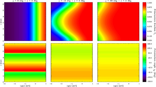
Contour plots in the energy-phase plane of the polarization fraction (top row) and the polarization angle (bottom row) for a neutron star with BP = 1013 G, RNS = 10 km and mass MNS = 1.4 M⊙. The inclination of the magnetic axis with respect to the spin axis is fixed to ξ = 5°, while the angle between the spin axis and the LOS is χ = 0° (left-hand column), 15° (middle column) and 30° (right-hand column). Seed photons are 100 per cent polarized in the X-mode.
The bottom row of Fig. 5 shows χp for the same three simulations. Contrary of what happens for the polarization fraction, the polarization angle does not depend on the energy and exhibits an oscillatory behaviour as a function of the rotational phase around a value of 90°. The amplitude of the oscillations depends on the geometrical angles and, for some combinations of χ and ξ, χp sweeps the entire range [0°, 180°] through a discontinuity, or ‘jump’. This is clearly seen in the bottom left panel of Fig. 5 where χ = 0, while χp is in between ∼70°–110° (bottom middle panel) and ∼80°–100° (bottom-right panel) for χ = 15° and χ = 30°, respectively. This is further illustrated in Fig. 6, which shows the polarization angle as a function of the rotational phase at a single energy (E = 0.02 keV), χ = 90° and different values of ξ for radiation 100 per cent polarized in the X-mode (solid lines) and in the O-mode (dashed lines). The amplitude of the oscillation vanishes in the case of an aligned rotator seen equator-on (χ = 90°, ξ = 0°) and increases for increasing ξ until the ‘jump’ appears for ξ = 90°.6 The average value of χp, instead, does not change with χ and ξ and is fixed by the polarization mode of the seed photons: it is 90° for X-mode photons and 0° for O-mode ones.7 It should be noted, however, that the mean value of the polarization angle is not univocally associated to the two photon modes, since it depends on the choice of the fixed reference frame (u, v, w), i.e. on the angle ψ introduced in Section 3.1. If, for instance, ψ = 90° (so that the u-axis coincides with the Y-axis of the LOS reference frame), the situation depicted in Fig. 6 is reversed, with the polarization angle for X-mode photons oscillating around 0° and that for the O-mode ones around 90°. Of course, different choices of the ψ angle do not affect the polarization degree ΠL, the amplitude of the oscillations of χP and the shift of 90° between the mean values of χP for X-mode and O-mode photons.
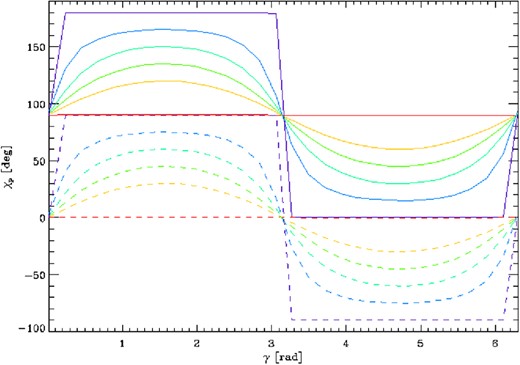
Polarization angle as a function of the rotational phase at a fixed energy (E = 0.02 keV), for χ = 90° and different values of ξ: 0° (red), 30° (orange), 45° (green), 60° (light blue), 75° (blue) and 90° (violet). The solid (dashed) lines correspond to seed photons 100 per cent polarized in the X-mode (O-mode). The values of RNS, MNS and BP are the same as in Fig. 5.
The behaviour of the phase-averaged polarization fraction as a function of the angles χ, ξ is shown in Fig. 7 for two values of the energy, E = 2 eV (optical) and E = 0.3 keV (X-rays). The right-hand panel illustrates the variation of the semi-amplitude of χP. As already noted by Fernández & Davis (2011), the amplitude is 180° for ξ ≲ χ when the phase-averaged polarization degree attains its minimum value (see Section 4).

Contour plots for the phase-averaged polarization fraction at optical (2 eV, left-hand panel) and X-ray (0.3 keV, middle panel) energies, and of the semi-amplitude of the oscillations of the polarization angle (right-hand panel), as functions of χ and ξ. The values of RNS, MNS and BP are the same as in Fig. 5.
The effects of varying the magnetic field strength are illustrated in Fig. 8, where χ = 15°, ξ = 5° and BP = 1012 G (left-hand panel), BP = 1013 G (middle panel; this is the same case shown in Fig. 5) and BP = 1014 G (right-hand panel). Again, changes are mostly in the polarization fraction ΠL (top row). Overall, the polarization fraction is smaller when the magnetic field is lower (top-left panel), and increases for increasing BP, reaching values ∼1 (i.e. the intrinsic polarization degree) in almost the entire energy range for BP = 1014 G (top-right panel), see Section 4. On the contrary, the polarization angle (bottom row) does not change much, exhibiting an oscillation between ∼70° and ∼110° at all the values of BP.
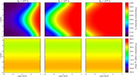
Same as in Fig. 5 for χ = 15°, ξ = 5° and three different values of the magnetic field: BP = 1012 (left-hand column), 1013 (middle column) and 1014 G (right-hand column).
Finally, Fig. 9 illustrates the effects on the polarization observables induced by the presence of a toroidal field component. The right-hand column shows the phase-energy contour plot of the polarization fraction (top panel) and a phase plot of the polarization angle at a fixed energy8 (bottom panel) for a globally twisted dipole field. The left-hand column shows for comparison the same quantities for a pure dipole with the same BP = 1013 G. The twisted magnetic field was evaluated using the analytical approximation by Pavan et al. (2009, see expressions in their appendix A), with a twist angle ΔϕN-S ≃ 50°. Since relativistic corrections are unavailable for a twisted field, they were not applied also to the dipole we show for comparison, whereas ray bending is still considered in both the cases. The effects of the twist on the polarization fraction are quite modest and the variation of ΠL with photon energy and rotational phase is nearly the same as in the pure dipole case. The only difference is in a slight overall decrease in the polarization degree.
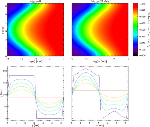
Polarization observables for the cases of a pure dipolar magnetic field (left-hand column) and a globally twisted dipole with twist angle ΔϕN-S ≃ 50° (right-hand column). Top row: polarization fraction in the energy-phase plane for χ = 15° and ξ = 5°. Bottom row: polarization angle as a function of the rotational phase for a fixed photon energy (E = 0.02 keV), χ = 90° and ξ = 0° (red), 30° (orange), 45° (green), 60° (light blue), 75° (blue) and 90° (violet). All the plots are obtained for seed photons 100 per cent polarized in the X-mode and values of RNS, MNS and BP as in Fig. 5.
The twist of the external field affects much more the polarization angle, as it can be seen from the bottom row of Fig. 9. The net effect is an overall asymmetry of the oscillations: χp sweeps a larger angle in a half-period with respect to the purely dipolar case; this effect increases with the twist angle ΔϕN-S, as already noticed by Fernández & Davis (2011).
4 DISCUSSION AND CONCLUSIONS
In this paper, we reconsidered the problem of the relation between the intrinsic and observed polarization properties in the case of surface emission from an NS. Our work extends previous investigations (Heyl et al. 2003; Lai & Ho 2003; van Adelsberg & Perna 2009) by providing the polarization observables for a large set of physical and geometrical parameters (i.e. the angles χ and ξ, the photon energy and the magnetic field strength and topology). Our treatment includes both ‘geometrical’ effects, due to the rotation of the Stokes parameters which is needed when the magnetic field is not constant across the emitting region, and ‘vacuum polarization’ (Heyl & Shaviv 2002); in order to make a full exploration of the parameter space possible, an approximated treatment of QED was used. This resulted in much shorter computational times, without losing significant physical accuracy, as the comparison with available results shows (Heyl et al. 2003). We checked that a typical run required about 100 min integrating equations (1) and only few tens of seconds using our approximation. Moreover, our approach allows to better disentangle the effects of QED and those due to the rotation of the Stokes parameters on the polarization signals. We stress that our main goal was not to compute polarization observables for a precise, physical model of surface emission, but to systematically illustrate the role of these two effects in making polarization patterns different from those of the original radiation. To this end, we assumed a quite simple picture in which the star magnetic field is a dipole and each surface patch emits a (isotropic) blackbody spectrum at the local temperature. Our results can be easily generalized to other magnetic configurations (the case of a globally twisted field is actually discussed here) and to different surface emission models. A (comparative) analysis of the polarization observables for emission from an atmosphere (van Adelsberg & Lai 2006, and references therein) or from a condensed surface (Potekhin et al. 2012, and references therein) will be the subject of a future paper (Gonzalez Caniulef et al., in preparation).
A crucial point in assessing the measured polarization properties is that the polarization state of a photon propagating in a magnetized vacuum (either ordinary or extraordinary) is strictly related to the choice of the reference frame. In fact, the photon polarization mode is defined only with respect to the plane fixed by the wavevector and the local magnetic field. This means that the Stokes parameters of each photon are in general referred to different frames, with the two axes orthogonal to the direction of propagation tailored on the direction of the local B-field (Section 2.2). However, photons are collected in the focal plane of an instrument, where a reference direction has been a priori introduced. This means that in order to obtain the polarization observables relative to the photons received by the instrument in a given exposure time, the Stokes parameters of each photon must be transformed to the polarimeter reference frame, through a rotation in the plane orthogonal to the LOS by an angle α, which depends on the magnetic field and viewing geometry, on the photon energy and on the position of the point from which photons were emitted (Section 3.1).
The effects induced by rotation of the reference frames compound those of vacuum polarization. According to QED, in fact, photons maintain their initial polarization state within the adiabatic region, while the polarization freezes at a larger distance (see Section 2.1). Despite the transition between the adiabatic and the outer zones is smooth, we assumed that there is a sharp boundary at the adiabatic radius ra (see equation 2). This enabled us to treat the photons as if they were emitted at ra, as far as their polarization state is concerned. This implies that the distribution of the α angles, by which each frame has to be rotated, is actually determined by the magnetic field at the adiabatic radius, and hence depends also on the distance ra from the star surface.
Simulations of polarization measurements (Section 3.3) clearly show that, because of the combined effects of frame rotation and QED, the measured polarization fraction can be very different from the intrinsic value, i.e. that of the radiation emitted at the surface. The differences appear to depend first on the viewing geometry, i.e. on the angles χ and ξ which give the inclination of the LOS and of the dipole axis with respect to the star spin axis. As shown in Fig. 5, the polarization dramatically decreases at all rotational phases for χ ≃ ξ ≃ 0. For χ not too close to ξ, ΠL has a minimum at the phase γ where the magnetic axis |$\boldsymbol {b}_\mathrm{dip}$| lies in the plane of the rotation axis and the LOS (either γ = 0 or 2π with our choice of the reference frame). This behaviour confirms the results of Heyl et al. (2003) and it is entirely due to the non-constant magnetic field across the emitting region: when a region of the star near to the magnetic poles is into view, the projection of |$\boldsymbol {B}$| in the plane orthogonal to the LOS is essentially radial, so that α can take values in the entire range [0, 2π]. Since the Stokes parameters for the whole radiation are obtained integrating the rotated Stokes parameters of single photons over the part of the star in view (see equations 28), the polarization degree has a minimum when the angle between |$\boldsymbol {b}_\mathrm{dip}$| and the LOS is minimum (and equal to |χ–ξ|, see the first of equations 12). On the other hand, the fact that ΠL does not change with rotational phase in the case shown in the top-left panel of Fig. 5, is precisely due to the fact that this is a nearly aligned rotator viewed along the rotational axis.
In agreement with the results by Heyl et al. (2003), we found that the behaviour of ΠL is also sensitive to the location of the adiabatic radius. From the top rows of Figs 5 and 8, it can be seen that the linear polarization fraction increases with the photon energy and the polar strength of the B-field: this reflects the dependence of ra on |$E^{1/5}B_\mathrm{P}^{2/5}$|. In fact, as equation (25) shows, cos α depends on the magnetic co-latitude and azimuth, θ and ϕ, through BX , BY; the two latter angles contain the factor RNS/ra (see equations C1 and C3). So, in the limit ra ≫ RNS (at least for axisymmetric magnetic field topology), α remains nearly constant as the emission point changes on the star surface, implying that the polarization fraction can be indeed approximated with |nX − nO|/(nX + nO), as equation (8) shows. Heyl et al. (2003) explained this behaviour as due to the fact that, in this limit, QED birefringence aligns the photon polarization angles. Actually, the weaker depolarization when ra ≫ RNS is due chiefly to the rotation of the Stokes parameters, vacuum polarization entering only implicitly through the dependence of the angle α on ra. Because of the dependence of ra on E and BP, this approximation becomes better the larger the photon energy and the stronger the polar B-field. Instead, the closer to the star surface the adiabatic limit, the smaller the overall measured polarization degree, the latter becoming vanishingly small if no adiabatic region is accounted for. So, the main conclusion is the more point-like the star is seen by an observer at the adiabatic boundary, the closer the measured ΠL is to the intrinsic linear polarization degree. A similar effect was noted by Heyl et al. (2003) in connection with the variation of the stellar radius.
On the other hand, the polarization angle exhibits quite a different behaviour. As Figs 5 and 8 show, χp does not change significantly with ra, since it does not depend on E and BP. This is because the factors RNS/ra within cos α tend to cancel out taking the ratio U/Q which defines χp (equation 7). The fact that χp keeps oscillating even when the measured polarization fraction is much smaller than the intrinsic one (see bottom-left panels of Figs 5 and 8) is a consequence of the frame rotation and not of QED effects. The polarization angle depends quite strongly, instead, on the geometrical angles χ and ξ (see e.g. the right-hand panel of Fig. 7). The polarization swing generally increases for decreasing χ at fixed ξ, as shown in Fig. 5. In particular, χp sweeps the entire range |$[0\circ ,180^\circ ]$| when the region close to the magnetic pole is always in view during the star rotation (bottom left panel), while the swing gets smaller for values of χ and ξ such that the polar region enters into view only at certain rotational phases. On the other hand, the oscillation amplitude in general grows for increasing ξ at fixed χ. This behaviour appears to be related again to the α-angle distribution, and provides an explanation for the correlation between the swing by 180° of the polarization angle and the low phase-averaged polarization fraction at χ < ξ, as already noticed by Fernández & Davis (2011, see also Wagner & Seifert 2000). In fact, the regions where the polarization angle spans the widest range correspond to those in which at least one among the Stokes parameters Q and U takes all the values between −1 and 1. Consequently, the averaged polarization fraction, obtained by summing the Stokes parameters over a rotational cycle, turns out to be very small, as shown in Fig. 7.
Phase-resolved polarization angle measurements, together with the information given by the linear polarization fraction, can help in understanding which polarization mode is the dominant one in the detected radiation. We showed in Fig. 6 that the mean value of χp depends on the mode in which the majority of photons are polarized. However, it is also related to the orientation of the (u, v) axes in the polarimeter plane (the ψ angle, see Section 3.1), which are fixed by the instrument design. In particular, the mean values of χp for X- and O-mode photons are always displaced by 90°, but they are 90° and 0°, respectively (as in the case in Fig. 6) only if ψ = 0. Hence, a measurement of the polarization angle alone fails in telling which is the prevailing polarization mode. The problem can be solved if also a phase-resolved measurement of the linear polarization fraction is available. In this case, since ΠL has a minimum when |$\boldsymbol {b}_ \mathrm{dip}$| intercepts the |$\boldsymbol {\Omega }\hbox{-}\boldsymbol {\ell }$| plane (see above), it could indeed be possible to individuate the direction of the X-axis on the plane of the sky. This allows to derive the angle ψ and to remove the inherent ambiguity in the measurement of χp.
Polarization observables can also provide information on the source geometry, i.e. the inclination of the LOS and of the magnetic axis wrt the rotation axis. In fact, as discussed earlier on, both the polarization fraction and the polarization angle strongly depend on the angles χ and ξ. As already shown in Taverna et al. (2014), if phase-resolved polarization signals are available, a simultaneous fit of ΠL and χp (possibly supplemented by that of the flux) allows to unequivocally derive the values of χ and ξ. On the contrary, this is in general not possible starting from phase-averaged measurements. The phase-averaged polarization fraction is largely degenerate with respect to the two angles, as clearly shown in Fig. 7 and, since the phase average polarization angle is constant in large regions of the χ–ξ plane, its measure is of no avail in pinpointing χ and ξ.
The effects of a different magnetic field topology on the polarization observables were assessed in the illustrative case of globally twisted dipolar magnetic field.9 The presence of a toroidal component in the external magnetic field slightly changes the behaviour of linear polarization fraction (see Fig. 9). In a twisted field, depolarization induced by the frame rotation is a bit stronger. This is due to the fact that Btwist > Bdip at any given position, because the toroidal component is roughly of the same order of the poloidal one, while the r-dependence is about the same for the two magnetic configurations. As a consequence, the adiabatic boundary moves a bit closer to the surface if BP and the photon energy are the same. A twisted field influences the polarization angle most, producing a strong asymmetry in the swing and a weak dependence on the energy (mainly at optical energies), as already discussed by Fernández & Davis (2011) and Taverna et al. (2014). The fact that the polarization angle is more sensitive to QED effects for a twisted magnetosphere than for a purely dipolar field, provides a strong signature of vacuum polarization effects (see Taverna et al. 2014).
Our analysis further demonstrates the need to properly account for QED and frame rotation effects in evaluating the observed polarization properties of radiation emitted by an NS. This is of particular relevance in relation to recently proposed X-ray polarimetry missions, which will certainly select NS sources as primary targets.
It is a pleasure to thank Enrico Costa for many illuminating discussions, Kinwah Wu for some useful comments and an anonymous referee, whose helpful suggestions helped us in improving a previous version of the manuscript. The work of RT is partially supported by INAF through a PRIN grant. DGC acknowledges a fellowship from CONICYT-Chile (Becas Chile). He also acknowledges financial support from the RAS and the University of Padova for funding a visit to the Department of Physics and Astronomy, during which part of this investigation was carried out.
A Mikheyev–Smirnov–Wolfenstein resonance which may induce mode conversion in X-ray photons for typical magnetar-like fields (B ≳ 1014 G).
This same quantity is called the polarization-limiting radius, rpl, in previous literature (see Heyl & Shaviv 2002).
As mentioned earlier, circular polarization is not considered in the present work.
The curves for ξ = 90° in Fig. 6 are box-like; the sloping lines are an artefact introduced by the finite resolution of the phase grid.
Actually the mean value is the same even if photons are not all polarized in the same mode; since the Stokes parameters for O- and X-mode photons have opposite signs and the polarization observables are obtained by summing the Stokes parameters over all photons, the mean value of χp reflects the polarization mode which dominates.
The twisted field actually introduces a dependence of χp on the photon energy. For the values of the twist angle we consider, however, this dependence is quite small.
We focused here only on surface emission, the interactions of photons with magnetospheric currents, chiefly through resonant cyclotron scattering, were ignored.
REFERENCES


