


Abstract
Recent dust continuum surveys have shown that filamentary structures are ubiquitous along the Galactic plane. While the study of their global properties has gained momentum recently, we are still far from fully understanding their origin and stability. Theories invoking magnetic field have been formulated to help explain the stability of filaments; however, observations are needed to test their predictions. In this paper, we investigate the structure and radial equilibrium of five filamentary molecular clouds with the aim of determining the role that magnetic field may play. To do this, we use continuum and molecular line observations to obtain their physical properties (e.g. mass, temperature and pressure). We find that the filaments have lower lineal masses compared to their lineal virial masses. Their virial parameters and shape of their dust continuum emission suggests that these filaments may be confined by a toroidal dominated magnetic field.
INTRODUCTION
Recent surveys of dust thermal continuum emission (e.g. ATLASGAL, Schuller et al. 2009; Bolocam, Nordhaus et al. 2008; Hershel infrared Galactic Plane Survey, Molinari et al. 2010) have shown that filamentary structures are ubiquitous along the Galactic plane. While filaments associated with well-known star-forming regions have been studied individually (i.e. those associated with Orion, Johnstone & Bally 1999; Taurus, Goldsmith et al. 2008; Lupus, Gahm, Johansson & Liseau 1993; Ophiucus, de Geus, Bronfman & Thaddeus 1990), these new surveys have identified a large number of filaments along the Galactic plane which allow us to obtain a census of these type of molecular clouds.
Despite their ubiquity and importance as hosts to the earliest stages of high-mass stars and clusters (e.g. Jackson et al. 2010), very little is known about the origin, stability and detailed physical properties of filaments and their embedded clumps.
A handful of recent works (e.g. Fiege & Pudritz 2000; Hernandez & Tan 2011) have focused on the identification of the mechanism that is responsible for the stability of filaments, and in particular whether magnetic fields play a role. Observationally, there is growing evidence that magnetic fields are associated with filamentary molecular clouds. Alves, Franco & Girart (2008) undertook optical polarimetry towards the diffuse gas in the Pipe nebula and found a large-scale magnetic field perpendicular to the main axis of the cloud. Chapman et al. (2011), studying the polarization of background starlight, also found a magnetic field perpendicular to the long axis of the filamentary region B213 in Taurus. These results are interpreted as evidence that the gas and dust within the cloud have collapsed along the field lines forming the filamentary clouds. In Orion, Poidevin, Bastien & Matthews (2010) measured the polarimetry of stars finding two components which they interpret to be a helical magnetic field wrapping around the filament.
Theoretically, the radial equilibrium of filamentary molecular clouds can be described by treating filaments as isothermal cylinders and using either pure hydrostatic models (Ostriker 1964) or those that included magnetic fields (Fiege & Pudritz 2000; Tilley & Pudritz 2003; Fiege et al. 2004). Because they have different predicted values for the density distribution and virial parameters, detailed observations of the gas and dust within and around filaments can help distinguish between these models.
Thus, to determine the radial equilibrium of filamentary molecular clouds, and whether magnetic fields play a significant role, we utilize data from the APEX Telescope Large Area Survey of the Galaxy (ATLASGAL) to identify a sample of filamentary molecular clouds. The continuum data from this survey combined with molecular line observations will allow us to determine the physical properties of these filamentary structures and to assess their radial equilibrium.
Sections 2 and 3 describe, respectively, the filaments selected and the observations performed. In Section 4, we calculate the physical properties of the filaments. In Section 5, we discuss the structure and radial equilibrium of the filaments and compare their properties with theories that explain the equilibrium of filamentary molecular clouds and in Section 6, we present a summary of the main points addressed in this paper.
IDENTIFYING FILAMENTS
To identify a sample of filaments, we selected a 20 square degree region of the Galactic plane centred at 335° Galactic longitude. This region was selected because it contained many filamentary structures in the dust continuum and a mix of both dark and bright regions of infrared emission. Selecting filaments for further study that span a range in star formation activity, and presumably evolutionary stage, is important particularly when attempting to establish a connection between filamentary structures and the formation of high-mass stars and clusters.
We selected all filaments from the ATLASGAL 870 μm images. To enhance the extended emission associated with each filament, we first applied a Fourier filter to the images to remove the small-scale peaks. From this smoothed image (only including emission >3σ), we selected five structures that appeared to be connected. With this method we recovered the Nessie Nebula (Jackson et al. 2010), a unique filamentary structure recently identified as an infrared dark cloud (IRDC) from Spitzer images. The potential filaments were named after the brightest clump embedded within them, using the denomination from the ATLASGAL compact source catalogue (Contreras et al. 2013). For simplicity, we also assign them a short denomination (A, B, C, D and E).
We used Spitzer Galactic Legacy Infrared Midplane Survey Extraordinaire (Benjamin et al. 2003) and MIPS Inner Galactic Plane Survey (MIPSGAL; Carey et al. 2005) images to characterize their associated infrared emission, which is an indication of their current star formation activity. Fig. 1 shows the Spitzer images overlaid with the dust continuum emission towards the selected filaments. This figure clearly shows the different infrared signatures associated with each filament. Parts of filaments ‘A: Nessie’, ‘B: AGAL337.406-0.402’ and ‘C: AGAL335.406-0.402’ are seen as IRDCs, although some bright IR emissions are associated with several of their dense clumps. These represent examples of filaments in a relatively early stage of formation. Filaments ‘D: AGAL332.294-0.094’ and ‘E: AGAL332.094-0.421’ show considerably brighter infrared emission and, thus, likely represent a more evolved state.
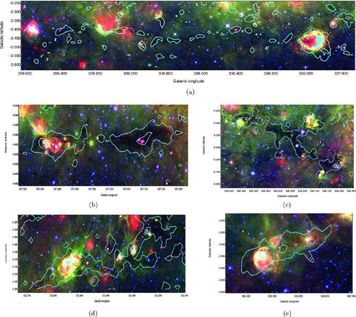
Three colour Spitzer images towards the five filaments selected overlaid with contours of the ATLASGAL 870 μm continuum emission (red: 24 μm MIPSGAL; green: 8 μm InfraRed Array Camera (IRAC); blue: 4.5 μm IRAC, contour levels are 3σ, 10σ and 20σ). Panels (a)–(e) show the images for each filament (A–E, respectively). In all cases, the filaments appear extended along the Galactic plane. Within them we see a range in star formation activity, from infrared-dark to infrared-bright regions.
OBSERVATIONS
For all the filamentary structures, we use the continuum data at 870 μm from ATLASGAL (Schuller et al. 2009) to determine their dust properties. These data were complemented with observations of the 350 μm continuum and 13CO(3–2) molecular line emission. The combination of these data will allow us to establish their physical coherence and properties.
ATLASGAL: 870 μm continuum survey
The ATLASGAL (Schuller et al. 2009) mapped dust thermal emission at 870 μm at high sensitivity with the aim of obtaining a complete census of regions of high-mass star formation within the Galaxy.
The survey was carried out from 2007 to 2010 using the Large APEX BOlometer CAmera (LABOCA) bolometer receiver (Siringo et al. 2009) mounted at the 12 m sub-millimetre Atacama Pathfinder EXperiment (APEX) antenna (Güsten et al. 2006), located in Llano de Chajnantor, Chile. The survey covered from ±60° in Galactic longitude, and ±1|${^{\circ}_{.}}$|5 in Galactic latitude. Also included in the surveyed region was the Carina arm, from −80° to −60° in Galactic longitude and −2° to +1° in Galactic latitude.
LABOCA is a 295 element bolometer array centred at 345 GHz with a bandwidth of 60 GHz, at this frequency the beam size of APEX is 19.2 arcsec. The errors in flux are estimated to be lower than 15 per cent (Schuller et al. 2009) and pointing |$\text{rms}$| is ∼4 arcsec. The final maps are generated with a pixel size of 6 arcsec, corresponding to a 1/3 of the telescope beam. The |$\text{rms}$| of the maps is typically 50 mJy beam−1 (see Schuller et al. 2009 for further details). More than 6000 compact sources have been identified within the Galactic plane coverage of this survey, with half of these sources showing no obvious evidence for current star formation (Contreras et al. 2013).
350 μm continuum emission
The 350 μm continuum observations were obtained using the Submillimeter APEX Bolometer Camera (Siringo et al. 2010), which consists of a bolometer array of 39 detectors, mounted on the APEX telescope. The beam size of APEX at this wavelength is 7 arcsec and the field of view is ∼90 arcsec. The observations were made using the on-the-fly (OTF) mode. To avoid imaging artefacts due to the scan mode, each map was observed twice at orthogonal scanning angles.
The observations were carried out during 2010 June, 2010 August and 2011 October. The images towards each filament were obtained by the combination of several small adjacent maps centred along the length of each filament. Details of the individual maps for each filamentary structure (centre position, size and time) are summarized in Table 1.
Summary of the observation towards the filaments.
| Center of individual maps | Continuum (350 μm) | 13CO(3–2) | ||||||
|---|---|---|---|---|---|---|---|---|
| Filament | RA | Dec. | Size | rms | Date | Size | rms | Date |
| (J2000) | (J2000) | (arcmin) | (Jy beam−1) | (arcmin) | (K) | |||
| A | 16:43:18.07 | −46:37:31.50 | 4.6 × 4.6 | 3.7 | Oct 2011 | 4.6 × 4.6 | 0.33 | Jun 2010 |
| 16:43:05.61 | −46:39:50.50 | 5.0 × 5.0 | 4.4 | Oct 2011 | 5.0 × 5.0 | 0.35 | Jun 2010 | |
| B | 16:37:36.23 | −47:41:35.55 | 5.5 × 5.8 | 2.5 | Aug 2010 | 5.4 × 5.8 | 0.20 | Aug 2010 |
| 16:38:35.32 | −47:30:15.21 | 5.4 × 5.8 | 1.5 | Aug 2010 | 5.3 × 5.9 | 0.49 | Aug 2010 | |
| 16:38:16.64 | −47:33:52.82 | 5.6 × 5.8 | 2.7 | Aug 2010 | 5.7 × 5.9 | 0.56 | Aug 2010 | |
| 16:37:57.02 | −47:37:47.75 | 5.4 × 5.7 | 0.7 | Aug 2010 | 5.5 × 5.5 | 0.63 | Aug 2010 | |
| 16:38:54.67 | −47:26:33.94 | 7.7 × 7.5 | 1.7 | Aug 2010 | 7.7 × 7.5 | 0.61 | Jun 2010 | |
| C | 16:30:11.36 | −48:48:02.33 | 9.3 × 7.9 | 1.6 | Jul 2010 | 4.9 × 10.6 | 0.44 | Jul 2010 |
| 16:29:52.64 | −48:53:20.96 | 7.5 × 9.1 | 0.9 | Jul 2010 | ||||
| 16:29:54.61 | −48:57:25.34 | 5.3 × 5.8 | 1.0 | Jul 2010 | ||||
| 16:29:35.92 | −48:57:51.62 | 5.7 × 6.1 | 1.0 | Jul 2010 | ||||
| 16:29:36.95 | −49:01:39.07 | 5.7 × 6.2 | 1.1 | Jul 2010 | 10.4 × 11.5 | 0.40 | Jul 2010 | |
| 16:29:06.65 | −49:00:33.41 | 7.3 × 8.5 | 1.4 | Jul 2010 | ||||
| 16:29:41.52 | −49:05:42.80 | 5.7 × 6.4 | 0.9 | Jul 2010 | ||||
| 16:29:35.91 | −49:09:01.85 | 4.0 × 5.2 | 1.1 | Jul 2010 | 4.5 × 6.6 | 0.46 | Jul 2010 | |
| D | 16:17:28.99 | −50:46:18.41 | 4.0 × 4.0 | 0.8 | Oct 2011 | 4.0 × 4.0 | 0.82 | Oct 2011 |
| 16:17:01.46 | −50:48:01.81 | 4.5 × 4.5 | 0.9 | Oct 2011 | 4.5 × 4.5 | 1.10 | Oct 2011 | |
| 16:16:42.84 | −50:50:16.61 | 4.0 × 4.0 | 1.0 | Oct 2011 | 4.0 × 4.0 | 0.89 | Oct 2011 | |
| 16:15:45.12 | −50:55:57.62 | 4.0 × 4.0 | 1.3 | Oct 2011 | 4.0 × 4.0 | 0.75 | Oct 2011 | |
| 16:15:34.65 | −50:55:42.83 | 4.0 × 4.0 | 1.0 | Oct 2011 | 4.0 × 4.0 | 0.73 | Oct 2011 | |
| 16:15:16.84 | −50:55:59.55 | 4.0 × 4.0 | 1.0 | Oct 2011 | 4.0 × 4.0 | 0.73 | Oct 2011 | |
| E | 16:16:26.20 | −51:17:45.83 | 8.9 × 9.2 | 0.7 | Aug 2010 | 8.9 × 9.3 | 0.46 | Oct 2010 |
| 16:18:04.70 | −51:08:27.65 | 4.0 × 4.0 | 0.4 | Oct 2011 | 5.5 × 5.5 | 0.90 | Oct 2011 | |
| 16:17:56.11 | −51:15:07.07 | 5.5 × 5.5 | 0.5 | Oct 2011 | 5.4 × 5.7 | 0.34 | Oct 2010 | |
| 16:17:23.77 | −51:17:10.16 | 5.5 × 5.5 | 0.7 | Oct 2011 | 5.9 × 5.3 | 0.32 | Oct 2010 | |
Pointing and focus checks were made using planets (Mars and Neptune where available). The flux calibration was made using planets and secondary calibrators with known fluxes: B13134, IRAS 16293, G5.89. Each flux calibration source was observed every hour, and skydips were also performed every hour to estimate the atmospheric opacity.
The data were reduced using boa1 software designed to read, handle and analyse bolometer array data. Each small orthogonal map observed was reduced and calibrated independently. Each map was opacity corrected, the base line was fitted and any point sources extracted. The noise in the map was reduced with a median-correlated noise filter and any spikes removed. After this step, the point sources were added back into the maps and the fluxes were calibrated. Overlapping orthogonal maps were then combined.
Once both orthogonal maps were added together, a signal-to-noise map and a mask with the emission over a threshold of 5σ (with σ being the rms of the map) were constructed. Once we obtained this mask, each map was re-reduced following the steps mentioned above, using the mask as input for the emission.
All the small maps were added together in boa to produce the larger map that covered each filament. Since the individual maps overlapped, the large map had a higher sensitivity than each individual map. Thus, we created a new mask for each filament and all the individual maps were re-reduced using this larger, more sensitive mask to recover the extended emission. This reduction process was needed to best extract the complex extended filamentary structures.
13CO molecular line emission
13CO(3–2) observations across the filaments were made using the APEX-2, superconductor–insulator–superconductor heterodyne receiver at APEX during 2010 June, 2010 August, 2010 October and 2011 October. The beam size of APEX is 18.2 arcsec at the frequency of the 13CO(3–2) line. The backend used during the 2010 observations was the Fast Fourier Transform Spectrometer (FFTS) and the eXtended FFTS was used during the observations in 2011 October. The velocity resolution of the spectra is 0.07 km s−1.
Small regions across the filament were mapped using the OTF mode. Since 13CO is ubiquitous along the Galactic plane, for the signal-free off position we used an absolute position below the Galactic plane to avoid contamination in the spectra. Table 1 gives the centre coordinates, the size of the mapped regions, the average noise and date of the observations.
The system temperature was calibrated prior to each observation using the chopper mode. Pointing and focus were made on IRAS 15194 every hour, the pointing accuracy was 2–3 arcsec. The average value of the water vapour column density ranged from 0.6 to 1.4 mm and the system temperatures were typically 300 K. TA were converted to |$T_{\text{MB}}$| using a mean beam efficiency, |$\eta _{\text{MB}}=0.73$|.
We used continuum and line analysis single-dish software to reduce each of the individual maps. For each spectrum a baseline was subtracted, using a three-degree polynomial. The data were then gridded and adjacent maps were then combined to produce large maps that covered each filament.
PHYSICAL COHERENCE AND PROPERTIES OF THE FILAMENTS
Physical coherence
Using the 13CO(3–2) molecular line observations, we are able to assess whether the filamentary continuum structures selected from the ATLASGAL maps correspond to a single physical structure or are the result of a projection effect from different clouds along the line of sight. For this, we use |$v_{\text{LSR}}$| measured along each filament to determine the continuity of the emission observed. We found that for all filaments, except B, the emission observed in the continuum images correspond to single physically coherent structure.
We note that our observations of ‘Nessie’ (filament A) cover only a small fraction of its length. The average velocity of the mapped region is −37 km s−1, consistent with the results of HNC(1–0) observations made by Jackson et al. (2010) towards the total extent of Nessie.
For filament B, we found that the dust continuum emission is associated with three discrete molecular clouds along the line of sight. A background cloud with average velocity of −48 km s−1, which will be excluded for the analysis of this filament; an elongated molecular structure, having an average velocity of −41 km s−1 that matches the morphology of the continuum emission, and which will be considered as the main filament; and a foreground cloud with an average velocity of −18 km s−1 located towards one side of the filament. This component will be taken into consideration when calculating the physical properties of this filament.
For filament C, the molecular line emission has an average velocity that ranges from −40 to −45 km s−1, suggesting that it corresponds to a single coherent molecular cloud. For filament D, we found that the molecular line emission has an average velocity of −48 km s−1, which we also interpret to arise from a single molecular cloud. For filament E, the emission has an average velocity of −53 km s−1.
Kinematic distance
We used the line velocity obtained from the 13CO(3–2) to derive their kinematic distances to each filament, using the rotational curve model described in Brand, Blitz & Wouterloot (1985).
Filaments A, B and C are clearly seen in extinction against the bright diffuse background; therefore, we assume they are at the near kinematic distance. While filaments D and E show both dark and bright IR emission, we also assume that they are at the near kinematic distance. The kinematic distances for the filaments are summarized in Table 2.
Summary of the derived properties of the filaments from the observations at continuum and molecular lines.
| Fil. | Dist. | Length | Radius | Δv | Temp. | Δvext | 〈ρext〉 | Lineal mass | Ps/k | 〈P〉/k | |||
|---|---|---|---|---|---|---|---|---|---|---|---|---|---|
| m | mvir | |$\frac{m}{m_{\rm vir}}$| | |||||||||||
| (Kpc) | (pc) | (pc) | (km s−1) | (K) | (km s−1) | (g cm−3) | (M⊙ pc−1) | (M⊙ pc−1) | (K cm−3) | (K cm−3) | |||
| A | 3.0 | 80 | 0.44 | 1.8 | 15 | 2.6 | 1 × 10⁻²¹ | 262 | 447 | 1.71 | 105 | 1.8 × 10⁶ | |
| B | 3.2 | 24 | 0.45 | 2.4 | 11 | 3.4 | 3.5 × 10⁻²¹ | 410 | 552 | 0.74 | 5.3 × 10⁵ | 107 | |
| C | 3.6 | 33 | 0.56 | 2.7 | 11 | 2.1 | 5.9 × 10⁻²¹ | 366 | 615 | 0.46 | 3.5 × 10⁴ | 1.4 × 10⁶ | |
| D | 3.3 | 26.6 | 0.52 | 2.1 | 12 | 3.2 | 3.7 × 10⁻²² | 291 | 380 | 0.76 | 4.9 × 10⁴ | 5.1 × 10⁶ | |
| E | 3.7 | 36.6 | 0.23 | 3.3 | 12 | 5.3 | 7.3 × 10⁻²² | 489 | 942 | 0.52 | 2.8 × 10⁵ | 2.5 × 10⁷ | |
Dust temperature
Because the colour temperature depends on the value of the spectral index β, we calculated the colour temperature using four different values for β: 1, 1.5, 2 and 2.5.
In all filaments, we found that the temperature increases towards the clumps, reaching in some clumps up to 100 K. In regions without obvious star formation, the average colour temperature derived for the filaments ranged from 8 to 20 K, depending on the value of β used. For the following analysis, a spectral index of β = 1.5 was chosen. The temperatures listed in Table 2 correspond to the ones obtained using this value of β.
Lineal masses along the filaments
For all filaments, we computed the mass per unit length (or lineal mass) from the dust continuum emission and the lineal virial mass from the 13CO(3–2) emission. We divided each filament along its length in sections, |$\text{d}x$|, with a width equal to the beam size (18 arcsec) and computed the mass in each of these segments.
For each section of the filament, we computed the 870 μm total flux by integrating the continuum emission across the diameter of the filament. From this, we computed the dust lineal mass, assuming a dust opacity of k870 = 0.012 cm2 g−1 and used the temperature profile obtained from the dust temperature analysis, taking into account, in this way, the temperature variations along the filament. The average value of the lineal mass obtained for all the filaments ranged from 142 to 400 M⊙ pc−1 (see Table 2).
Because the 13CO(3–2) observations indicate that for part of filament B the observed emission is actually the superposition of two discrete molecular clouds, the lineal dust mass derived for this filament is likely to arise from the combination of both molecular clouds. From the molecular line information, we can determine the virial mass of both molecular clouds. The foreground molecular cloud, at −18 km s−1, has a mean line width of Δv = 1.3 km s−1, which gives a mean lineal virial mass of 258 M⊙ pc−1 and a total virial mass of ∼103 M⊙. This correspond to ∼25 per cent of the total mass derived (foreground + filament) if we assume the two components were one coherent cloud. Therefore, for further analysis, we take this contribution into consideration deriving a ‘corrected’ mean lineal dust mass and ‘corrected’ total dust mass for this filament.
For the filaments, the average value of the virial lineal mass ranged from 447 to 942 M⊙ pc−1 (see Table 2). We find that the average value of the virial lineal mass is higher than that of the lineal mass derived from the dust continuum emission, which at face value suggests that the filaments are not in equilibrium and may be expanding. Hence, for the filament to be in virial equilibrium in the absence of high external pressure, a magnetic field may be required to confine the filament.
External and internal pressure
We found that the average value for the line width in the regions outside the filaments ranged from 2.1 to 5.3 km s−1. The corresponding densities ranged from 0.6 to 7 × 10⁻²² g cm−3. Using these values, we derive external pressures ranging from Ps/k = 3.5 × 10⁴ to 5.3 × 10⁵ K cm−3. These are comparable to the values obtained for the external pressure towards other filamentary molecular clouds (e.g. Hernandez & Tan 2011).
The internal pressure was computed using the 13CO(3–2) line width and the density obtained for each point |$\text{d}x$| along the filament. The density was obtained by dividing the lineal mass by the volume per unit length (πR2) at each point along the filament which was estimated using the derived radii, R.
The average line widths ranged from 1.8 to 3.3 km s−1, and the average density found ranged from 0.9 − 6.2 × 10⁻¹⁹ g cm−3. Using these values, we derived internal pressures ranging from 〈P〉/k = 1.4 × 10⁶ to 2.5 × 10⁷ K cm−3.
STRUCTURE AND RADIAL EQUILIBRIUM OF THE FILAMENTS: THE ROLE OF MAGNETIC FIELDS
Several observation have, however, shown that large scale magnetic fields are present towards giant molecular clouds (e.g. Alves et al. 2008; Chapman et al. 2011). Thus, a more general theory to explain the stability of filamentary molecular clouds should include the presence of large-scale ordered magnetic fields (Fiege & Pudritz 2000; Tilley & Pudritz 2003; Fiege et al. 2004). Fiege & Pudritz (2000) found that when including magnetic fields the density profile falls off as r−1.8 to r−2, much shallower than that predicted by equation (4) (r−4). This shallower slope agrees well with observations of filamentary molecular clouds [e.g. L977 (Alves et al. 1998) and IC 5146 (Lada 1998)]. A density profile of r−1.8 to r−2 is in agreement with the presence of a toroidal magnetic field wrapping around the filament, which prevents the filament from expansion (Fiege & Pudritz 2000).
The value of |$\mathcal {M}$| can be positive or negative, depending on the strengths of the poloidal and toroidal components of the helical magnetic field. If |$\mathcal {M}>0$|, then the magnetic field is poloidal dominated, if |$\mathcal {M}<0$| then the magnetic field is toroidal dominated. If |$\mathcal {M}=0$|, then the helical configuration of the magnetic field would have a neutral effect on the radial equilibrium of the filament, and the non-magnetic form of the virial equation is recovered.
The value of |$\mathcal {M}/|\mathcal {W}|$| can be constrained by measuring the values of m/mvir and Ps/〈P〉 from observations. Fiege & Pudritz (2000) computed the values of |$\mathcal {M}/|\mathcal {W}|$| for seven filamentary molecular clouds, using values of mass and pressure taken from the literature. They found that most of these filaments have values of |$\mathcal {M}/|\mathcal {W}|$|< 0, which corresponds to a dominant toroidal magnetic field.
Radial density profile analysis
To compare our observations to these theories, we first divided the emission within the filament into two groups: a group containing the clumps and a group containing the interclump material. Since the shape of the filament's radial intensity is only characterized by the value of p and |$R_{\text{flat}}$|, we averaged and normalized the radial intensity for each group. Thus, we obtained for both the clumps and interclump material a mean value for the radial intensity from the 870 and 350 μm emission. The radial intensity at each point along the filament was fitted using equation (8), for both the emission at 870 and 350 μm, using k870 = 0.012, k350 = 0.073 cm2 g−1, respectively, and the derived dust temperature.
Fig. 2 shows an example of the fit made to the emission towards the clumps and interclump material in filament D (the rest of the filaments show similar intensity profiles). We found that for all the filaments there is a clear difference between the profile obtained towards the clumps and interclump material. Table 3 summarizes the values obtained for the fit towards the clumps and interclump material in each filament. The mean values of the intensity profile for the clumps and interclump material suggest that while the radial profile observed towards the clumps can be described by hydrostatic equilibrium the interclump material cannot.
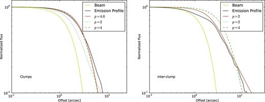
Normalized intensity profile of the 870 μm emission from filament D (black line). The solid yellow line indicates the beam profile. The red solid line represents the best fit to the intensity profile. Left-hand panel: radial intensity profile of the emission from the clumps. Its shape can be well fitted by a profile with p = 4 (hydrostatic solution; green dashed line). Right-hand panel: intensity profile of emission from the interclump material. Its shape can be well fitted by a profile with p = 2 (magnetic solution; green dotted line).
Summary of the values of p obtained for the fits towards the clumps and interclump material within each filament. This table shows that the clumps are best fitted by profiles with values of p between 3.5 and 4, while the interclump material is best fitted by profiles with p ∼ 2.
| Filament | Clump | Interclump | ||
|---|---|---|---|---|
| 870 μm | 350 μm | 870 μm | 350 μm | |
| A | 5.0 | − | 3.0 | − |
| B | 3.5 | 4.8 | 2.0 | 2.0 |
| C | 3.9 | 5.0 | 3.1 | 2.1 |
| D | 4.5 | 4.0 | 2.0 | 2.1 |
| E | 3.4 | 3.9 | 2.6 | 3.0 |
| Filament | Clump | Interclump | ||
|---|---|---|---|---|
| 870 μm | 350 μm | 870 μm | 350 μm | |
| A | 5.0 | − | 3.0 | − |
| B | 3.5 | 4.8 | 2.0 | 2.0 |
| C | 3.9 | 5.0 | 3.1 | 2.1 |
| D | 4.5 | 4.0 | 2.0 | 2.1 |
| E | 3.4 | 3.9 | 2.6 | 3.0 |
Summary of the values of Ps/〈P〉, m/mvir and |$\mathcal {M}/|\mathcal {W}|$| for all the filaments.
| Filament | Clump | Interclump | Average | ||||||
|---|---|---|---|---|---|---|---|---|---|
| Ps/〈P〉 | m/mvir | |$\mathcal {M}/|\mathcal {W}|$| | Ps/〈P〉 | m/mvir | |$\mathcal {M}/|\mathcal {W}|$| | Ps/〈P〉 | m/mvir | |$\mathcal {M}/|\mathcal {W}|$| | |
| A | 0.121 | 0.8 | −0.1 | 0.03 | 0.03 | −34.0 | 0.06 | 0.1 | −8.4 |
| B | 0.020 | 1.2 | 0.2 | 0.10 | 0.4 | −1.6 | 0.05 | 0.7 | −0.3 |
| C | 0.001 | 1.1 | 0.1 | 0.004 | 0.3 | −2.0 | 0.025 | 0.6 | −0.7 |
| D | 0.010 | 1.0 | 0.1 | 0.02 | 0.4 | −1.3 | 0.009 | 0.8 | −0.3 |
| E | 0.003 | 0.7 | −0.5 | 0.005 | 0.3 | −2.0 | 0.012 | 0.5 | −0.9 |
For the filaments, a non magnetized isothermal model does not describe well the shape observed in the dust intensity profile. Because an isothermal model with a toroidal dominated magnetic field reproduces well the observed profiles, we speculate that the filaments may be wrapped by a magnetic field which is confining them against expansion. While we cannot firmly conclude the existence of a magnetic field, the derived radial intensity profiles are suggestive of a toroidal dominated field.
Virial equilibrium analysis
We also analysed the radial equilibrium of the filaments by studying the relationship between their lineal mass, lineal virial mass, internal pressure, external pressure, gravitational energy and magnetic field via equation (5). Using the values obtained for each filament, we computed the values of |$\mathcal {M}/|\mathcal {W}|$| (see Table 4).
Fig. 3 shows a Ps/〈P〉 versus m/mvir diagram for different values of the ratio between the total magnetic energy per unit length, |$\mathcal {M}$|, and lineal gravitational energy, |$|\mathcal {W}|$|. Also shown are the values obtained for the clumps (triangles), the interclump material (dots) and the average value of each filament (stars). For the interclump material, we found values of |$\mathcal {M}/|\mathcal {W}|$| ranging from −1.3 to −34 suggesting the presence of a toroidal magnetic field. The average values of |$\mathcal {M}/|\mathcal {W}|$| for the whole filaments range from −0.3 to −8.4 also suggesting the presence of a toroidal dominated magnetic field.
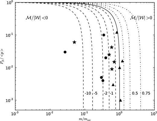
Ps/〈P〉 versus m/mvir diagram. The lines indicate model results. Dashed: toroidal magnetic fields; solid: solution with neutral magnetic field, including the unmagnetized solution; dotted: poloidal magnetic field. The symbols indicate the derived values for our filaments. Stars: average value for each filament; dots: values for clumps; triangles: values for the inter-clump material.
For the clumps, we found that the average value of |$\mathcal {M}/|\mathcal {W}|$| ranges between −0.5 and 0.2, suggesting that in these structures the role of the magnetic fields are not very important. For this calculation, to compare directly the clump and interclump material, we use the same form of the virial equilibrium used to describe a filament. Because the clumps are probably spherical, this assumption may not be appropriate. Nevertheless, the fact that our virial equilibrium analysis suggest a toroidal magnetic field towards the interclump material but neutral in the clumps may be the result of the processes that lead to the formation of clumps within the filaments.
This virial equilibrium analysis suggests that if we treat the filament as a whole coherent structure, the values obtained for their lineal mass, virial lineal mass, external and internal pressure suggest that their equilibrium can be explained by the presence of a toroidal dominated magnetic field that prevents the filament from expansion. This result is also consistent with the analysis of the radial density profile which suggest that the filaments need a magnetic field to explain their radial equilibrium.
SUMMARY
We used dust continuum data at 870 and 350 μm and molecular line data from five filaments in order to derive their properties and study their structure and radial equilibrium. Our main result and conclusions are summarized as follow.
A comparison of the lineal dust masses and their lineal virial masses reveal, in all five filaments, lower values for their lineal dust masses, suggesting that an additional mechanism to gravity is needed to prevent these filaments from against expansion.
The radial intensity profile of the dust emission at 870 and 350 μm are similar. We find that the radial intensity profile of the dust emission from regions containing clumps and interclump material exhibit different shapes. Towards the regions where the clumps are located, the radial intensity profiles are well fitted by a theoretical profile with an index p = 4. This profile describes the classical model of an isothermal, non-magnetic, cloud in hydrostatic equilibrium (Ostriker 1964).
On the other hand, the radial intensity profile towards the interclump material are well fitted by a profile with an index p = 2, which describes an isothermal filament, with magnetic field confinement.
Considering the whole filament (i.e. interclump and clump region), the mean intensity profiles are well fitted with models with a radial density of r−2 (i.e. p = 2), suggesting that filaments are well represented by models where magnetic fields are needed for their radial equilibrium. This type of profile has also being observed in other filamentary molecular clouds reported in the literature such as IC 5146 (Lada, Alves & Lada 1999) or L977 (Alves et al. 1998).
In summary, the analysis of the radial column density and of the virial equilibrium suggests that filaments are best modelled as isothermal filamentary molecular clouds wrapped by a helical, toroidal dominated magnetic field. This magnetic field would confine the filamentary molecular cloud preventing its expansion and potentially influencing the formation of clumps within it. One suggestion is that the clumps might form along the filaments at the location where the magnetic field crosses the filaments; however, direct measurements of the magnetic field would be useful to corroborate this hypothesis.
We thank the referee Jason Fiege for his valuable comments that significantly improved this paper. YC and GG gratefully acknowledge support from CONICYT through projects FONDAP No. 15010003 and BASAL PFB-06.
