


Abstract
We study the dynamical structure of a cooling dominated rotating accretion flow around a spinning black hole. We show that non-linear phenomena such as shock waves can be studied in terms of only three flow parameters, namely the specific energy  , the specific angular momentum (λ) and the accretion rate
  of the flow. We present all possible accretion solutions. We find that a significant region of the parameter space in the
  plane allows global accretion shock solutions. The effective area of the parameter space for which the Rankine–Hugoniot shocks are possible is maximum when the flow is dissipation-free. It decreases with the increase of cooling effects and finally disappears when the cooling is high enough. We show that shock forms further away when the black hole is rotating compared to the solution around a Schwarzschild black hole with identical flow parameters at a large distance. However, in a normalized sense, the flow parameters for which the shocks form around the rotating black holes are produced shocks closer to the black hole. The location of the shock is also dictated by the cooling efficiency in that higher the accretion rate
  , the closer is the shock location. We believe that some of the high-frequency quasi-periodic oscillations may be due to the flows with higher accretion rate around the rotating black holes.
1 INTRODUCTION
The accretion on to black holes (BHs) is thought to be an essential process in BH astrophysics since the gravitational potential energy released by the infalling matter is directly related to the emitted power from the vicinity of a BH (Frank, King & Raine 2002). In the last three decades, a number of papers have reported extensive studies of accretion disc models around gravitating objects by the several groups both theoretically as well as through numerical simulations (Novikov & Thorne 1973; Shakura & Sunyaev 1973; Page & Thorne 1974; Lynden-Bell 1978; Hawley, Smarr & Wilson 1984a,b; Eggum, Coroniti & Katz 1988; Chakrabarti 1989; Nobuta & Hanawa 1994; Yang & Kafatos 1995; Chakrabarti 1996a; Lu & Yuan 1997; Gammie 1999; Fukumura & Tsuruta 2004). In 1980s it was realized that an accreting matter becomes transonic around a galactic and extragalactic BH in order to satisfy the inner boundary conditions at the event horizon. A fully general relativistic theoretical work of Chakrabarti (1996b) showed that multidimensional sub-Keplerian flows exhibit discontinuous shock transitions for a significant region of the flow parameter space spanned by the specific energy and the specific angular momentum in a non-dissipative flow. Recently, it has been pointed out that the shock waves formed around a BH could be a very useful tool in explaining the observational results. The hot, dense post-shock flow could be the natural site for generating high-energy photons (Chakrabarti & Mandal 2006). In particular, Chakrabarti & Mandal (2006) reported that non-thermal electrons may be processed around the shock fronts by particle acceleration mechanism that could produce emitted radiation up to few MeV by inverse Comptonization of non-thermal synchrotron radiations. In addition, the observed quasi-periodic oscillations (QPOs) in wide frequency range may be originated due to some type of resonance oscillation of the post-shock flow (Molteni, Sponholz & Chakrabarti 1996; Chakrabarti, Acharyya & Molteni 2004; Okuda, Teresi & Molteni 2007), or due to dynamical oscillations of the sub-Keplerian flows (Ryu, Chakrabarti & Molteni 1997). This oscillation is governed by the infalling time-scale of matter in the post-shock region. Since a shock may form very close to a spinning BH, it could possibly explain the origin of high-frequency QPOs also. Thus, it would be worthwhile to study the behaviour of the shock waves around a rotating BH for more realistic cases by addition of cooling processes inside the disc. This is all more important since the post-shock pressure, which holds the shocks in place, depends on the cooling processes.
So far, major progresses on the theoretical front have taken place only when the accretion flow around the rotating BH is thin and when the energy dissipation processes are inefficient (Chakrabarti 1996b). In reality, the accreting matter should be affected by the various cooling processes, such as bremsstrahlung and synchrotron cooling, most significantly the latter as the magnetic field is expected to be present in the disc. Some theoretical work along this line has recently been completed (Das 2007). However, the effects of synchrotron cooling on the dynamical structure of the accreting flow around a rotating BH has not yet been studied well. Indeed, the study of accretion flows with various energy dissipation processes around a compact object in the general relativistic limit is very complex. Recently, Chakrabarti & Mondal (2006) proposed a pseudo-Kerr potential which describes the space–time geometry around a rotating BH quite satisfactorily for the BH spin parameter, ak, − 1 ≤ak≤ 0.8. This pseudo-potential, which is an extension of the concept laid down while writing the Paczynski–Wiita potential (Paczynski & Wiita 1980) in Schwarzschild geometry allows us to study very complex behaviour of dissipative accreting matter around a rotating BH in a very simple and elegant way.
In an optically thick and geometrically thin accretion flow, cooling processes reduce the bulk energy of the flow during accretion while viscosity not only heats the flow but also redistributes the angular momentum in the disc. The cooling is governed by the density and temperature of the flow while viscosity is assumed mainly due to ion collisions or its coupling with the magnetic field. A realistic disc can have some viscosity, but as Chakrabarti & Das (2004), Chakrabarti (1996a) already pointed out, standing shock exits even in presence of significant viscosity. Thus, in this paper we shall explore the properties of shock waves in presence of cooling alone. In other words, our focus here is to deal with the accretion flows having low angular momentum up to the marginally bound value. However, we argue that basic conclusions regarding our idealized inviscid solution would be qualitatively similar to the viscous solution. We wish to report viscous solutions elsewhere in the future.
The suitability of the pseudo-Kerr potential that we employ has been well tested for both particle dynamics and fluid dynamics (Chakrabarti & Mondal 2006; Mondal & Chakrabarti 2006) which allows us to use this for our present study with sufficient confidence. We identify all possible accretion solution topologies including the ones which may allow standing shock transitions. In this paper, we only focus on thin, non-dissipative shock waves. We separate various regions in the parameter space according to the solution topologies. We identify a special region where standing shock conditions [Rankine–Hugoniot shock conditions (RHCs); Landau & Lifshitz 1959] are not satisfied but accretion solution continues to have three critical points. Solutions of this kind generally exhibit oscillating shock as in Ryu et al. (1997) when Schwarzschild geometry was used. In the present paper, we ignore bremsstrahlung cooling process since it is very inefficient compared to the synchrotron loss (Chattopadhyay & Chakrabarti 2000), especially in flows around stellar mass BHs. We also do not consider Compton cooling effect. These will be carried out in future.
In the next section, the governing equations are presented. In Sections 3 and 4, the accretion solutions are shown. We discuss the shock properties in Section 5. In the final section, we make concluding remarks.
2 THE GOVERNING EQUATIONS
In this section, we present a set of relevant equations that governs the dynamical structure of a stationary, thin, viscous, axisymmetric accretion flow on to a rotating BH. In addition, we assume an ideal equation of state for accreting gas. The equations are written on the equatorial plane of the accretion disc in the frame of the so-called zero angular momentum observers, and are as follows (Chakrabarti 1996a; Das 2007):
- the radial momentum equation:1

- the mass flux conservation equation:2

- the angular momentum conservation equation:3

 and Σ and Wxφ are the vertical averaged density and the viscous stress of the flow. The terms s, T, Q+ and Q− represent the specific entropy, the local temperature, the energy gained and the energy lost by the flow, respectively. In our model, the accreting flow is assumed to be in hydrostatic equilibrium in the vertical direction of the flow motion. The half-thickness h(x) of the disc is then obtained by equating the vertical component of the gravitational force and the pressure gradient force:
 . The adiabatic sound speed is denoted by a and defined as
  . In the weak viscosity limit, Wxφ is negligible and the angular momentum distribution remains uniform throughout the disc.
The flow equations have been made dimensionless by considering unit of length, time and the mass as GM BH/c2, GM BH/c3 and MBH, respectively, where G is the gravitational constant, MBH is the mass of the BH and c is the velocity of light, respectively. Henceforth, all the flow variables are expressed in geometrical units.


 is the accretion rate in units of Eddington rate that regulates the efficiency of cooling. Following Mondal & Chakrabarti (2006), we use modified polytropic index [n= (γ− 1)−1] relation as n→ n + (0.3-0.2ak) and choose β= 10 throughout the paper, until otherwise stated.
3 SONIC POINT ANALYSIS


4 ACCRETION SOLUTION
In order to obtain a complete accretion solution, we choose the inner sonic point location (xin) and the angular momentum (λ) of the flow as input parameters (Das 2007). From the inner sonic point, we integrate inward up to the BH horizon and outward till the outer edge and combine them to obtain a global transonic solution.
4.1 Shock solution
In Fig. 1, we present a global solution with a standing shock around a rotating BH. The variation of the Mach number with the logarithmic radial distance is plotted. The flow parameters are  and ak= 0.5, respectively. The figure consists of two solutions. The one passing through the outer sonic point (O) connects the BH horizon and the outer edge of the disc. The other passing through inner sonic point (I) is closed and is connected with the BH horizon only. Arrows indicate the direction of the flow towards the BH. Matter starts accreting from the outer edge of the disc with a negligible velocity. As the flow accretes towards the BH, the flow gains its radial velocity due to the attraction of the strong gravity. The flow becomes supersonic after crossing the outer sonic point (O) and continues to accrete towards the BH. The RHCs (Landau & Lifshitz 1959) in turn allow the flow variables to make a discontinuous jump in the subsonic branch. This is indicated by a dotted vertical line and commonly known as the shock transition. In the post-shock region, the flow momentarily slows down and subsequently picks up the radial velocity and enters into the BH supersonically after crossing the inner sonic point (I). In this particular case, the shock conditions are satisfied at xs= 48.57. The entropy generated at the shock is eventually advected towards the BH to allow the flow to pass through the inner sonic points. In this paper, the shocks are considered to be thin and non-dissipative.

Variation of Mach number (M=u/a) with logarithmic radial distance. Flow parameters are  and ak= 0.5. Standing shock forms at xs= 48.57.
4.2 Parameter space for multiple sonic points
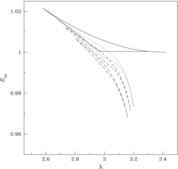
So far, we have seen that the shock wave connects two solution branches – one passing through the outer sonic point and the other passing through the inner sonic point. In particular, the flow with multiple saddle type sonic points may undergo shock transitions. More importantly, for shock formation in dissipative accretion flows, the solution passing through the inner sonic point has to be spiralling in (Das 2007). Therefore, it would be useful to study the parameter space for accretion flows having spiral-in solution passing through the inner sonic point. In Fig. 2, we show the classifications of parameter space as a function of accretion rate  in the
  plane. Here,
  denotes the energy of the flow at the inner sonic point (xin). The BH rotation parameter is chosen as ak= 0.5. The region bounded by the solid curve is obtained for non-dissipative accretion flows. The regions under the dotted and dashed curve is obtained for higher accretion rates
  and 0.0125, respectively. As accretion rate
  is increased, the parameter space for multiple sonic points shrinks. This indicates that nature of sonic points changes (from saddle to spiral) for flow with identical input parameters for increasing
  .
.
Parameter space for multiple sonic points. The effective regions bounded by the solid curve are for cooling-free accretion flow. Regions under dotted and dashed curves are obtained for  and 0.0125, respectively. Effective area of parameter space reduces with the increase of accretion rate
  as it enhances the cooling efficiency.
5 SHOCK PROPERTIES
5.1 Shock dynamics
In Fig. 3, we present the variation of shock locations with the accretion rate  . Logarithmic radial distance is varied along the horizontal axis and Mach number is plotted along the vertical axis. The vertical lines represent the shock locations. Matter with identical outer boundary conditions is injected subsonically from the outer edge of the disc xinj= 300 on to a rotating BH with rotation parameter ak= 0.5. The local energy of the flow at xinj is
  (including the rest mass) and the angular momentum is λ= 3.0. The subsonic flow crosses the outer sonic point to become supersonic and makes a shock transition to the subsonic branch. The solid vertical lines represent the shock location (xs= 26.03) for non-dissipative flow. As cooling is incorporated, shock front moves forward. In the post-shock region, cooling is more effective compared to the pre-shock flow as the density and the temperature are very high in this region due to compression. Cooling reduces the post-shock pressure causing the shock front to move inward to maintain pressure balance across it. For higher
  , shock front moves further inward. The dotted, dashed and dot–dashed vertical lines represent the shock locations xs= 19.38, 15.85 and 13.45 for
  and 0.0375, respectively.
![Mach number variation with logarithmic radial distances. Flows are injected subsonically from the outer edge xinj= 300 with identical energy and angular momentum λ= 3.0. Different accretion rates are used. Solid curve represents a solution including the shock wave (xs= 26.03) for cooling-free accretion flow. Other solutions are for []= [0.0125, 19.38] (dotted), [0.025, 15.85] (dashed) and [0.0375, 13.45] (dot–dashed). As is increased, shock front precedes towards BH.](https://oup.silverchair-cdn.com/oup/backfile/Content_public/Journal/mnras/389/1/10.1111_j.1365-2966.2008.13564.x/1/m_mnras0389-0371-f3.jpeg?Expires=1750344726&Signature=2XMut6a1D3cLkTw4e9pNwfLg1exoTtGENVdPV9-YyjvUoCjJZt9fFZpyALdoN3tfR4txEJlMirvml6jQPxNkHt9yOqwSiRYylQSXorzfknff4ITAJlSQjyWJhzsRJo-F7qea3FPMGkEHn55~vCBAqc0Y9KWSCwM~7V371WnGRyB~WtO1PVHHd7RL-y4MaXB4DTqqoVciW3pLmDn7DKWxjJb~qffq-ghYNQ3ArXO4uh96DgIKCZlcdZtlZiwv04qvtFzD52QU2GUf~L-ax2f7mtOGibmEv9dyp9m4udKjTEixVjUdhxU1UB5amyGKjCwJVD8A2VDBfbHcUOJ7pqdmSw__&Key-Pair-Id=APKAIE5G5CRDK6RD3PGA)
Mach number variation with logarithmic radial distances. Flows are injected subsonically from the outer edge xinj= 300 with identical energy  and angular momentum λ= 3.0. Different accretion rates
  are used. Solid curve represents a solution including the shock wave (xs= 26.03) for cooling-free accretion flow. Other solutions are for [
 ]= [0.0125, 19.38] (dotted), [0.025, 15.85] (dashed) and [0.0375, 13.45] (dot–dashed). As
  is increased, shock front precedes towards BH.
In Fig. 4(a), we show the variation of the shock location as a function of accretion rate  for a set of angular momentum (λ). In this particular figure, the flow is injected from the outer edge of the disc (xinj= 300). The BH rotation parameter is chosen as ak= 0.5. The angular momentum of the flow is varied from λ= 2.94 (small dashed) to 3.04 (solid) with an interval Δλ= 0.02. At the injection point, the corresponding local energies of the flow (from bottom to top) are
  (small dashed), 1.003 170 (big dashed), 1.003 167 (small–big dashed), 1.003 163 (dot–dashed), 1.003 160 (dotted) and 1.003 156 (solid), respectively. For a given accretion rate
  , the shock forms further out for flows with higher angular momentum. Here, the larger angular momentum increases the centrifugal pressure which pushes the shock front outside. Conversely, for a given angular momentum, the shock location decreases with the increase of the accretion rate as cooling reduces the post-shock thermal pressure. Fig. 4(a) shows that the standing shocks are formed for a wide range of accretion rate
  . In each angular momentum, the standing shocks disappear beyond a critical value of accretion rate
  as the RHCs are not satisfied here. Non-steady shocks may still exit, but an investigation of such phenomena is beyond the scope of the present paper. As λ increases, the critical accretion rate first increases, becomes maximum at some λ (= 2.96, in this particular case) and then decreases. This clearly indicates that the parameter space for the standing shock shrinks in both the lower and higher angular momentum sides with the increase of the accretion rate.
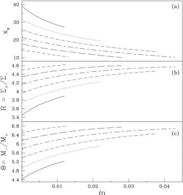
(a) Variation of the shock location with accretion rate  . Flows are injected with the same energy and angular momentum from the outer edge. Small-dashed, big-dashed, small–big dashed, dot–dashed, dotted and solid curves are drawn for angular momentum λ= 2.94, 2.96, 2.98, 3.0, 3.02 and 3.04, respectively. (b) Variation of compression ratio (R=Σ+/Σ−) with accretion rate for the same set of parameters as in (a). (c) Variation of shock strength (Θ=M−/M+) with the accretion rate for the same set of parameters as in (a). Subscripts ‘+’ and ‘−’ denote quantities before and after the shock.
One of the important components in accretion disc physics is to study the density profile of matter since the cooling efficiency as well as the emitted radiation directly depends on it. We compute the compression ratio R defined as the ratio of vertically averaged post-shock to pre-shock density and plot it in Fig. 4(b) as a function of accretion rate  for the same set of flow parameters as in Fig. 4(a). For a given angular momentum (λ), the compression ratio increases monotonically with higher
  . As
. As  increases, post-shock flow becomes more compressed to provide required pressure for holding the shock. In addition, for a given
  , higher angular momentum flow feels less compression in the post-shock region as centrifugal pressure resists the flow to accrete. Note that, for each angular momentum, there is a cut-off at a critical accretion rate limit as standing shock conditions are not satisfied there.
It is useful to study another shock property called shock strength Θ (defined as the ratio of pre-shock to post-shock Mach number of the flow) as it is directly related to the temperature jump at the shock. In Fig. 4(c), we show the variation of shock strength as a function of accretion rate  for flows with identical input parameters as in Fig. 4(a). For a given angular momentum (λ), the strength of the shock is the weakest in the dissipation-free limit and it becomes stronger as accretion rate
  is increased. Thus, a higher cooling causes the post-shock flow to be hotter and radiations emitted from this region are expected to be harder. A similar result is reported by Mandal & Chakrabarti (2005). This clearly indicates that the observed spectra of the BH would strongly depend on the cooling.
An important part of understanding a cooling dominated accreting flow around a rotating BH is to study the shock properties as a function of BH rotation parameter ak. In Fig. 5(a), we plot the variation of shock location as a function of ak. In this particular figure, we inject matter from the outer edge xinj= 200 and the accretion rate is considered to be  . Solid, dotted and dashed curves are obtained for flows with angular momentum λ= 2.96, 3.05 and 3.14, respectively. The corresponding energies at the injection point are
  and 1.003 422, respectively. Note that, for a given λ, shocks form for a particular range of ak. As ak increased, shock recedes from the BH horizon. Moreover, shocks exist around a weakly rotating BH when the flow angular momentum is relatively higher and vice versa. This phenomenon is directly related to the spin–orbit coupling term in the Kerr geometry. In fact, since both the marginally bound and the marginally stable angular momenta (as well as their difference) go down when the Kerr parameter is increased, the relevant parameter region when the shocks form also goes down as ak is increased. In general, however, the shock location is generally small for higher ak, as statistically the flow with a smaller angular momentum (and therefore, the lesser centrifugal force) is accreted in a rapidly spinning BH. Thus, for instance if we compared the shock locations having λ=λms for all cases, the shock location for a rotating BH would be closer for higher ak.
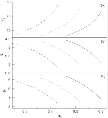
Variation of (a) shock location, (b) compression ratio and (c) shock strength with BH rotation parameter ak. See text for more details.
In Fig. 5(b), we show the variation of the compression ratio as a function of BH rotation parameter ak for the flows with input parameters same as Fig. 5(a). The solid, dotted and dashed curves are obtained for λ= 2.96, 3.05 and 3.14, respectively. The compression ratio R decreases with the increase of ak for flow with identical λ. In Fig. 5(c), we plot the variation of shock strength Θ with ak for flow with input parameters as in Fig. 5(a). We obtain a similar variation of Θ with ak as in Fig. 5(b).
5.2 Parameter space for shock formation
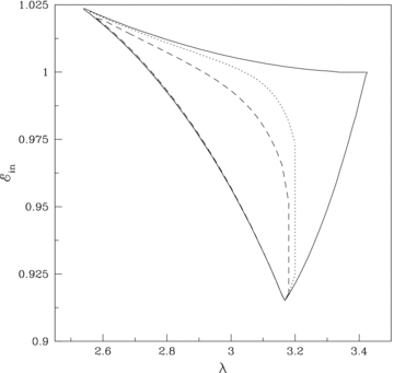
In Fig. 6, we identify the region of the parameter space that allows the formation of the standing shocks. The BH rotation parameter is considered to be ak= 0.5. The region bounded by the solid curve is obtained for non-dissipative accretion flow. As accretion rate is enhanced, the effective region of parameter space for standing shocks shrinks in both the lower and higher angular momentum sides. Due to the cooling effect, the flow loses its energy as it accretes and therefore, the parameter space is shifted to the lower energy domain for higher cooling. The regions under dotted, dashed and dot–dashed curves are obtained for accretion rates  and 0.01, respectively. It is clear that the standing shocks do not exist beyond a critical accretion rate when the synchrotron cooling is present.
Variation of the effective region of parameter space which forms standing shocks as a function of the accretion rate  . See the text for more details.
In Fig. 7, we classified the entire parameter space spanned by  according to the nature of solution topologies. As an example, we consider ak= 0.5 and
  . We separate the parameter space into six regions marked by S, OS, O, I, CI and N. The dot–dashed line represents the rest-mass energy of the flow. At the bottom left-hand side of the parameter space, we plot solution topologies in the small boxes. In each box, Mach number of the flow is plotted against the logarithmic radial distance. Each of these solutions are marked and drawn using the parameters from the corresponding region of the parameter space. The direction of the accreting flow is indicated by the arrow. (The solutions without arrows are relevant for winds, discussions on which are beyond the scope of this paper.) The solutions from the regions marked ‘S’ and ‘OS’ have two X type sonic points and the entropy at the inner sonic point is higher than that at the outer sonic point. Flows from ‘S’ suffer a standing shock transition as RHCs are satisfied. However, a solution from the region ‘OS’ does not pass through the standing shock as RHCs are not satisfied here. A flow with parameters from this region is unstable and causes periodic variation of emergent radiation from the inner part of the disc as it tries to make a shock transition but fails to do so. This is known from the numerical simulations of non-dissipative flows Ryu et al. (1997) and we anticipate that a similar behaviour would be seen in this case as well. The solutions from region ‘I’ possess only the inner sonic point and the accreting solutions straight away pass through it before entering into the BH. A solution from region ‘O’ has only one outer sonic point. The solution from region ‘CI’ has two sonic points – one ‘X’ type and other ‘spiral’ type. Solutions of this kind do not extend to the outer edge of the disc to produce a complete global solution and therefore becomes unstable. It has been pointed out by Chakrabarti (1996a) that inclusion of viscosity should open up the topology to allow the flow to reach a larger distance to join with a subsonic Keplerian flow. The region marked ‘N’ is the forbidden region for a transonic flow solution.
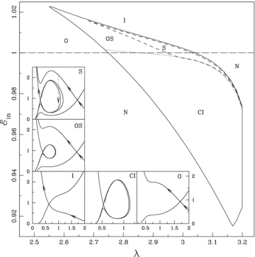
Classification of parameter space according to the various solution topologies of BH accretion solution. See text for details.
6 CONCLUDING REMARKS
In this paper, we have studied the properties of cooling dominated accretion flow around a rotating BH by solving a set of equations that regulate the dynamical structure of the flow. A special consideration is given to synchrotron cooling that strongly affects the disc properties as well as the emitted spectrum and luminosity that are observed.
We obtain the global accretion solutions with and without the shocks in terms of a few flow parameters, namely energy, angular momentum, BH rotation parameter and the accretion rate, which effectively acts as the cooling parameter. We find that the accreting matter experiences a centrifugal force which acts as a barrier, inducing a shock formation. We show that the global shocked accretion solution can be obtained for a significant region of the parameter space even when the cooling is significant. Using a conventional accretion disc model we expect the accretion to take place when the angular momentum is close to the marginally stable value. Our calculation shows that the region is actually broader, in terms of both the angular momentum and energy.
The discussion regarding the nature of the sonic point has been reported in many occasions (Chakrabarti & Das 2004; Das & Chakrabarti 2004). However, a detailed analysis was not presented before for a cooling dominated flow around a rotating BH. Our present paper suggests that a large region of the parameter space provides a stable saddle type sonic point. In Fig. 2, we demonstrated that the parameter space for the stable saddle type sonic point is gradually reduced with the increase of cooling efficiency.
We show that the standing shocks form closer to a spinning BH as the accretion rate is enhanced. At the post-shock region, the density and the temperature are relatively high compared to the pre-shock flow and thus cooling is more efficient there. For a higher cooling, the post-shock matter cools faster, reducing the thermal pressure drastically. This forces the shocks to move inward to maintain pressure balance across them.
One of the aims of the present paper was to study the effect of BH rotation parameter on the dynamical structure of cooling dominated global solutions. We find that for flows with identical outer boundary condition (e.g. same energy and angular momentum at the outer edge) shock recedes from the BH horizon with the increase of BH rotation parameter (ak). However, if we choose the relevant angular momentum for each case, such as the marginally stable angular momentum the shock location moves in with the increase of ak. The range of ak for which the stationary shocks are formed is restricted for a flow of given angular momentum. Shocks are possible around a rapidly rotating BH when the flow angular momentum is relatively low. Since that produces a very low centrifugal pressure, the shock can form very close to the BH for a rapidly spinning BH.
We identify the region of parameter space for the formation of a standing shock. We find that the effective region of the parameter space for the stationary shock shrinks when the accretion rate is enhanced. This suggests that the possibility of shock formation decreases for higher accretion rate. In addition, we also separate a region where the Rankine–Hugoniot relation is not satisfied. In the context of invidcid flows, it has been observed that the flow parameters from such a region give rise to oscillating shocks (Ryu et al. 1997). The reason is that the higher entropy at the inner sonic point forces the flow to pass through it by generating extra entropy at the shock. But since RHCs are not satisfied the shock cannot settle itself at a given location. Thus the cause of oscillation is sufficiently generic and we suspect that exactly the same thing will happen in the present case. Most importantly, since rotating BHs may have shocks very close to the horizon, the frequencies of such oscillations are expected to be higher.
Our present findings suggest that shocks, standing or oscillating, do form around the spinning BHs and it may be an essential ingredient since shocks could successfully explain the observed stationary (Chakrabarti & Mandal 2006) as well as time-dependent behaviour of the radiations from the BH candidates (Chakrabarti et al. 2004; Okuda et al. 2007). We demonstrated that the shocks form closer to the BH as cooling is increased. This will enhance the QPO frequency as it is proportional to the infalling time-scale (Molteni et al. 1996; Chakrabarti & Manickam 2000) and thus the QPO frequency may vary in a wide range starting from mHz to KHz depending on the accretion rate. This understanding also generally agrees with the observational results. Recent reporting of the outbursts of GRO 1655−40 showed a clear evidence of the QPO frequencies increasing monotonically from about 90 mHz to 17 Hz (Chakrabarti et al. 2005) in a matter of 15 d and this could be easily fitted using the shock propagating at a constant velocity (Chakrabarti et al. 2005).
The formalism presented here does not include outflows/jets which may be generated from the inner part of the disc as a result of deflection of inflowing matter due to excess thermal pressure at the shock front (Das et al. 2001; Chattopadhyay & Das 2007; Das & Chattopadhyay 2008). Since the outflows/jets are ejected evacuating the inner part of the disc, it will necessarily reduce the post-shock pressure and therefore, shock front has to move in to retain the pressure balance. This suggests that the result should be affected if the accretion–ejection mechanism is considered together. We plan to consider this study in a future work and it will be reported elsewhere.
We have approximated the effect of general relativity using the pseudo-Kerr gravitational potential. This pseudo-Kerr potential has been successfully tested to retain most, if not all, of the salient features of the flows in a Kerr metric. The use of this approach allows us to find out the non-linear shock solutions in a curved space–time geometry in a simpler way. We believe that our basic results would be qualitatively the same with fully general relativistic calculations, especially for ak < 0.8 for which the pseudo-Kerr potential was found to be satisfactory.
SD was supported by KOSEF through Astrophysical Research Centre for the Structure and Evolution of the Cosmos (ARCSEC). SKC thanks a visit to Abdus Salam International Centre for Theoretical Physics where part of this work was completed.
REFERENCES
