


Abstract
We perform a detailed spatially resolved, spectroscopic, analysis of the core of the Centaurus cluster of galaxies using a deep Chandra X-ray observation and XMM–Newton data. The Centaurus cluster core has particularly high metallicity, up to twice the solar values, and we measure the abundances of Fe, O, Ne, Mg, Si, S, Ar, Ca and Ni. We map the distribution of these elements in many spatial regions, and create radial profiles to the east and west of the centre. The ratios of the most robustly determined elements to iron are consistent with solar ratios, indicating that there has been enrichment by both Type Ia and Type II supernovae. For a normal initial stellar mass function, the metallicity peak represents the products of about 4 × 10¹⁰ M⊙ of star formation. This star formation can have occurred continuously at a rate of 5 M⊙ yr−1 for the past 8 Gyr or more, or was part of the formation of the central galaxy at earlier times. Either conclusion requires that the inner core of the Centaurus cluster has not suffered a major disruption within the past 8 Gyr, or even longer.
1 INTRODUCTION
X-ray observations of the intracluster medium in clusters of galaxies allow us to measure the integrated enrichment in these objects over their lifetime. The two main contributors to the metals in clusters are Type Ia and Type II supernovae. The expected ratio of the yields of various elements is quite different. Type II explosions should produce significantly more α-element yield relative to Fe than Type Ia events. Therefore by studying the relative abundances of elements, it is possible to determine the relative contribution of different enrichment mechanisms, and so learn about the star formation history of these objects (Renzini 2004).
Local clusters of galaxies are enriched to around 1/3 of the solar value (as determined mainly by the Fe abundance; e.g. Edge & Stewart 1991). Clusters with highly peaked surface brightness distributions, traditionally known as cooling flow clusters, have higher average X-ray emission-weighted metallicities than those without (Allen & Fabian 1998). In addition, these peaked clusters show metallicity gradients, with large abundances in their cores (e.g. Fukazawa et al. 1994; De Grandi & Molendi 2001).
Data from the ASCA X-ray observatory allowed many studies to be made of the metallicity of clusters, given its better spectral resolution compared to previous missions. Mushotzky et al. (1996) examined four clusters in the temperature range 2.5–5 keV, removing the centrally peaked regions. They concluded the abundance ratios observed were consistent with Type II supernovae. Fukazawa et al. (1998) examined 40 clusters, concluding that relative contribution of Type II enrichment increases towards richer systems, with Type Ia enrichment being more important in lower mass systems.
Recently, Baumgartner et al. (2005) examined all the cluster observations in the ASCA archive, performing a stacked analysis. Their conclusion is that generally Si and Ni are overabundant with respect to Fe, but Ar and Ca are very underabundant. Therefore the degree of enrichment of α-elements is not the same. The Fe, S and S abundances did not consistently match a combination of theoretical Type Ia and Type II products.
Recently, XMM–Newton and Chandra have been used to make detailed analyses of clusters, examining the variation of different metals as a function of radius, and mapping them (e.g. Sanders et al. 2004). Matsushita, Finoguenov & Böhringer (2003) examined an XMM observation of M87. They found no evidence for a gradient in Fe/Si, but found O to have a flatter gradient than Fe or Si. From the lack of O emission in the very central regions, they concluded that Type Ia enrichment is dominant there. Werner et al. (2006) examined the 2A 0335+096 cluster in detail, finding 25 per cent of the supernovae contributing to enrichment were of Type Ia, and 75 per cent Type II.
The Centaurus cluster, Abell 3526, is a nearby (z= 0.0104; Lucey, Currie & Dickens 1986) bright galaxy cluster (LX,2−10 keV= 2.9 × 1045 erg s−1; Edge et al. 1990).
The cluster is notable for its steep abundance gradient (Fukazawa et al. 1994; Ikebe et al. 1999; Allen et al. 2001). The central region is very rich in metals (Sanders & Fabian 2002), reaching twice solar abundance in iron (Fabian et al. 2005). In addition, the high-metallicity region is mostly to the west of the cluster (Sanders & Fabian 2002), and there appears to be a drop in abundance in the very central region. This drop is not due to resonance scattering (Sanders & Fabian 2006).
Any abundances we show in this paper are relative to the commonly used photospheric solar metallicities of Anders & Grevesse (1989). In this set of abundances, Fe has a number density of 4.68 × 10⁻⁵ relative to H. We use a redshift for the Centaurus cluster of 0.0104, and assume H0= 70 km s−1 Mpc−1, which gives a scale of 213 pc per arcsec. All uncertainties shown are 1σ. Positions use J2000 coordinates.
2 DATA PREPARATION
2.1 Chandra data sets
The Chandra data sets examined in this paper are listed in Table 1. The ACIS-S3 aimpoint was offset from the X-ray peak slightly by different amounts to dither the observation to help remove CCD artefacts.
Chandra data sets examined in this paper and their observation date. The exposure shown is the total exposure after periods with the flares are removed. The combined exposure is 195.4 ks. The offsets applied to the observations are in the y-coordinate of the CCD.
| Obs | Sequence | Date | y-offset (arcmin) | Exposure (ks) |
|---|---|---|---|---|
| 504 | 800012 | 2000-05-22 | −1.0 | 21.5 |
| 505 | 800013 | 2000-06-08 | −1.0 | 9.7 |
| 4954 | 800401 | 2004-04-01 | −1.3 | 80.0 |
| 4955 | 800401 | 2004-04-02 | −0.8 | 40.1 |
| 5310 | 800401 | 2004-04-04 | −1.8 | 44.1 |
We investigated the results using both the standard caldb calibration and the data corrected for charge transfer inefficiency (CTI) using the Penn State University corrector (PSU; Townsley et al. 2002a,b). CTI has degraded the energy resolution of the ACIS CCDs since the launch of Chandra. ACIS contains both front-illuminated (FI) and back-illuminated (BI) CCDs. The effect of CTI has been greatest on the FI CCDs. It is thought the damage is due to focused protons. The gates of the FI CCDs are unprotected by covering silicon, and are damaged more quickly.
The standard analysis tools correct data from the FI CCDs for this effect, but not for BI data. The ACIS-S3 CCD is a BI CCD, and is a popular choice of primary detector for Chandra users due to its comparatively high effective area at lower energies, and its higher spectral resolution. The degradation of spectral resolution changes the width of spectral lines, and so is potentially important for metallicity determination. We therefore investigated whether correcting for CTI has a significant effect in abundance determinations, which we discuss below.
For the non-CTI-corrected data, we reprocessed each data set using the most recent appropriate gain file, acisD2000-01-29gain_ctiN0003.fits, applying time-dependent gain correction. Using a light curve from the ACIS-S5 CCD (which is a BI CCD, like ACIS-S3) in the 2.5–7 keV band (as recommended by Markevitch 2002), we filtered each event file using the ciaolc_clean tool. This yielded a total exposure time of 195.4 ks.
When CTI correcting, we reprocessed each level-1 event file with the PSU corrector, removed standard event grades and applied the same time filtering as above.
We used blank-sky background observations when fitting the spectra from each of the data sets. In order for the background spectra to be independent for each data set, we split a single blank-sky background up into three for the 4954, 4955 and 5310 observations, keeping the ratio of the background exposure to the observation to be the same. As the Chandra ACIS background is slowly increasing as a function of time, we therefore adjusted the exposure of each of the blank-sky event files in order for the 9–12 keV rate of photons in the background observation on the S3 CCD to be the same as the observation.
2.2 Creating spectra and responses
When spectral fitting the Chandra spectra, rather than attempt simultaneously fitting of spectra from each of the data sets, we added together the spectra before fitting. In addition, we generated response and ancillary response files for each spectral region for each of the data sets. The response files for the data sets were added together, weighting according to the number of photons between 0.5 and 7 keV in the corresponding spectrum. The background spectra appropriate for each foreground data set were merged together to make a total background spectrum. This was done by discarding random photons from the background spectra, effectively making the exposure time shorter, until the ratio of the exposure time of each background spectrum to the total background matched the ratio of the exposure times of each respective foreground spectrum to the total foreground. We only considered the ACIS-S3 when spectral fitting.
The adding procedure is valid if the response of the detector is similar between each observation. This is the case, except for the build up of contaminant on the ACIS detector over time. We tested the method by comparing the results from spectral fitting against those from fitting the spectra simultaneously. We saw no systematic changes in results.
For the non-CTI-corrected data, we generated response matrices and ancillary response matrices using the mkacisrmf and mkwarf tools, weighting each CCD region according to the number of counts between 0.5 and 7 keV. We used a single response matrix across the entire ACIS-S3 CCD for the CTI-corrected data, generated with high-energy resolution. mkwarf was applied to generate ancillary responses, but using the quantum efficiency uniformity (QEU) file of the PSU corrector.
2.3 XMM–Newton observation
In Section 4, we examine the radial variation of the properties of the cluster. In this analysis, we also examine an XMM–Newton observation of the cluster which goes out to larger radius than the Chandra observations. We examined XMM observation identifier 0046340101. The data were reduced using the standard tools, and were filtered using the same criteria as used by Read & Ponman (2003) to create their backgrounds. This yielded 26.7 and 31.4 ks of time on the MOS1 and MOS2. There was no PN data remaining after filtering. Background spectra were taken from the blank-sky data sets of Read & Ponman (2003), normalizing to match the count rate of detector outside of the telescope field of view. The exposure times of the backgrounds were adjusted so that the count rate in the 9–11 keV band, where there is little cluster signal, matched the foreground spectra.
When spectral fitting, the two MOS data sets were fit simultaneously, but the relative normalizations of the two instruments were allowed to vary to account for any variation in effective area. The spectra were fit between 0.5 and 7 keV. Except for the simultaneous fit of the two data sets, we used the same spectral fitting procedure as the Chandra data, which is detailed below.
3 TWO-DIMENSIONAL ANALYSIS
We selected regions on the surface brightness images containing a signal-to-noise ratio of 200 or greater (over 40 000 counts) using the contour binning technique (Sanders 2006). The algorithm selects regions which have the same surface brightness on an image by binning pixels with nearest fluxes on a smoothed map until a signal-to-noise threshold is reached. In this case, the image was smoothed using the accumulative smoothing algorithm to give a minimum signal-to-noise ratio of 30. We also constrained the geometry of the bins so that new pixels were not added if they are further away than 1.8 times the radius of a circle with the same area as the bin currently. This produces bins which are more compact than would be the case otherwise.
In all the Chandra analyses, point sources listed in Table 2 were excluded from the regions. These point sources are not shown in the abundance maps.
Point sources excluded from the Chandra data, in RA order. Also shown is the radius of the excluded circle in arcsec.
| RA | Dec. | Radius (arcsec) | RA | Dec. | Radius (arcsec) | RA | Dec. | Radius (arcsec) |
|---|---|---|---|---|---|---|---|---|
| 12h48m22.61s | −41°21′ 36.1″ | 4.9 | 12h48m39.29s | −41°20′ 24.6″ | 2.5 | 12h48m55.32s | −41°19′ 02.2″ | 1.0 |
| 12h48m23.53s | −41°21′ 27.1″ | 4.4 | 12h48m39.75s | −41°19′ 27.0″ | 1.5 | 12h48m56.17s | −41°19′ 23.8″ | 0.8 |
| 12h48m26.14s | −41°17′ 56.3″ | 5.4 | 12h48m41.45s | −41°20′ 48.0″ | 1.9 | 12h48m56.90s | −41°14′ 50.1″ | 3.1 |
| 12h48m29.56s | −41°18′ 49.0″ | 2.8 | 12h48m41.63s | −41°19′ 28.0″ | 2.3 | 12h48m56.96s | −41°19′ 21.2″ | 1.3 |
| 12h48m29.84s | −41°22′ 49.3″ | 3.7 | 12h48m42.40s | −41°17′ 11.5″ | 2.1 | 12h48m59.82s | −41°15′ 59.0″ | 2.4 |
| 12h48m30.89s | −41°19′ 31.3″ | 6.1 | 12h48m42.84s | −41°16′ 09.5″ | 2.8 | 12h48m59.99s | −41°14′ 40.7″ | 4.3 |
| 12h48m30.93s | −41°22′ 43.2″ | 2.8 | 12h48m42.99s | −41°22′ 48.8″ | 4.4 | 12h49m01.57s | −41°20′ 34.5″ | 1.5 |
| 12h48m31.33s | −41°18′ 26.4″ | 1.7 | 12h48m43.04s | −41°15′ 41.7″ | 3.5 | 12h49m02.50s | −41°14′ 41.2″ | 4.3 |
| 12h48m32.51s | −41°18′ 32.1″ | 2.9 | 12h48m43.53s | −41°20′ 06.4″ | 1.9 | 12h49m03.16s | −41°18′ 49.9″ | 1.2 |
| 12h48m35.54s | −41°15′ 02.5″ | 3.4 | 12h48m44.17s | −41°16′ 10.5″ | 1.9 | 12h49m03.62s | −41°20′ 50.2″ | 1.8 |
| 12h48m36.51s | −41°18′ 21.3″ | 2.4 | 12h48m46.62s | −41°15′ 39.5″ | 2.0 | 12h49m05.84s | −41°15′ 39.8″ | 2.4 |
| 12h48m38.99s | −41°19′ 41.0″ | 2.2 | 12h48m48.76s | −41°16′ 07.1″ | 1.8 | 12h49m06.24s | −41°17′ 51.1″ | 2.5 |
| 12h48m39.26s | −41°17′ 39.0″ | 2.8 | 12h48m53.44s | −41°19′ 12.9″ | 1.2 |
We extracted spectra from each of the regions, grouping each spectrum to contain a minimum of 20 counts per spectral channel. We fitted the spectra using spectral models made up of one, two and three temperature components. In the fits, the O, Ne, Mg, Si, S, Ar, Ca, Fe and Ni abundances were allowed to be free. We assumed each temperature component had the same abundance. In the fits, we also allowed the temperatures, normalizations of the components and Galactic absorption to be free. The spectra were fit between 0.5 and 7 keV to minimize the χ2 statistic. We used an F-test to decide between the single-, double- and triple-component fits. If the double temperature fit gave an improvement over the single temperature fit with a probability of 0.27 per cent improvement by chance (corresponding to 3σ), then we used that. If the triple-component fit gave the same minimum improvement over the double fit, then that was used.
3.1 Spectral codes
There are a few spectral models in use in X-ray astronomy for optically thin, collisional plasmas as found in clusters. These include mekal (Mewe, Gronenschild & van den Oord 1985; Mewe, Lemen & van den Oord 1986; Kaastra 1992; Liedahl, Osterheld & Goldstein 1995) in xspec using the ionization balance of Arnaud & Rothenflug (1985) and Arnaud & Raymond (1992). xspec (Arnaud 1996) is the standard X-ray spectral fitting package, which we use here. mekal can be calculated in real-time during spectral fitting, or used by interpolation in temperature of pre-calculated spectra. We use the calculation option as the tables are inaccurate at low temperatures, and have poor spectral resolution.
A more recent code is apec (Smith et al. 2001b), also available in xspec, where we use the latest available version, 1.3.1. This model uses pre-calculated tables generated from the Astrophysical Plasma Emission Data base (APED; Smith et al. 2001a). The tables are more accurate than the xspecmekal tables, as the spectral lines are stored in a separate list to the continuua spectra, and so spectral resolution is not an issue. It has also enabled us to include the effects of linewidth in the model (now included in the version provided in xspec).
The mekal code has also been developed over time, but these changes are not present in the version in xspec. They are, however, present in the spectral analysis package spex (Kaastra 2000). Until now, it has not been possible to use the updated version of mekal, which we call spex in this paper for convenience, in xspec. Nevertheless, it is easy to generate continua spectra and lists of lines for the spex model in the spex spectral fitting package for a set of temperatures. We were able to take these data and generate apec format table models from it, again storing the continuum separately from the lines. This has allowed us to compare the results using the three different models with the same analysis techniques in the same analysis package, xspec. Reassuringly, the results obtained on our CCD resolution spectra using mekal and spex are very similar.
To examine the differences more systematically, we plot in Fig. 1 the abundances obtained from the apec and spex codes for each of the regions against the metallicity using mekal, without using the CTI corrector. There is generally very good agreement between mekal and spex. The main difference appears to be that fewer regions require multitemperature fits statistically using spex, leading to the abundances for a few outlying points to be changed. If you compare the quality of the fits between the two models, there is virtually no difference.
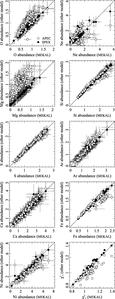
Comparison of metallicities and reduced χ2 obtained with the apec and spex spectral codes against those using mekal. As spex is based on mekal, the results obtained are very similar.
There are many more differences between the results obtained using apec and mekal. We wish to emphasize that the increased scatter in Fig. 1 does not imply that apec is worse than spex, but just that it is less similar to mekal. The O metallicities are substantially larger using apec, the Mg abundances are larger, whilst Ni is slightly smaller. Ne is poorly correlated, indicating that these models disagree over the peak of the Fe–L emission. The models agree over Si, S, Ar and Ca metallicities. There are some differences for regions of high Fe abundance. In Centaurus, this is where the gas is the coolest and so Fe–L lines are more important, and multiple temperature components more prevalent. The differences are also slightly seen at high Si and S metallicities. The quality of the fits produced by apec is generally better than the mekal model.
3.2 Metal determination
With the low spectral resolution CCD data we are using here, we cannot determine metallicities using the strengths of individual lines. Spectral models are used to predict the spectrum, which is folded through the instrument response, and compared to the real data. The problem with this approach is that if the spectral model is incomplete or inaccurate, or the calibration of the instrument is uncertain, then the derived abundances can be wrong.
However, if an element produces strong lines, or lines which are separated in energy from other elements, then its metallicities are less likely to suffer from systematics. We show in Fig. 2 a spectrum from the western sector of the cluster, with a radius of 2.6–12.6 kpc. The main line positions are labelled.
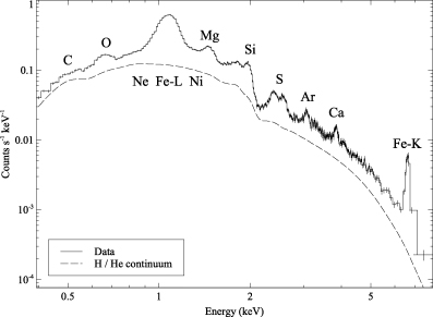
Example spectrum from annuli 3–6 of the western sector (see Fig. 10). Also plotted is a two-component model fit where the abundances have been set to zero afterwards, except for H and He. Labelled are the positions of the strongest lines of each element.
It can be seen that the strongest line at this temperature range is the Fe–L line complex. This is especially dominant in the cooler region of the cluster. Further out, the Fe–K lines become more important. The Fe–L lines can be very sensitive to the temperature of the gas, and so it is important to include a sufficient range of the temperature components in the spectral fitting to ensure the abundance is accurate. There is some additional complexity as the Ne, Mg and Ni–L lines are close in energy to Fe–L, and these can affect the Fe–L abundance. The strength of the Fe lines means that the statistical error on its metallicity is very low. We do use at least two spectral codes in our analysis, however, and they show very similar trends.
The Si lines are the next strongest. Unfortunately, there is another potential systematic, which is that the Ir coating of the Chandra mirrors produces a steep drop in the effective area at around 2.05 keV due to the Ir M edge (see spectrum). This means that if the effective area is not calibrated sufficiently well, this could affect the Si signal. XMM shows a similar feature near 2 keV, due to an Au edge, affecting Si determination. However, the Si abundances obtained with Chandra and XMM agree well (see Section 4). Some of the weaker Ni and Mg lines affect the Si lines.
S is a robustly determined element, with a small leakage of signal from the neighbouring Si lines.
Ar and Ca should be accurately determined elements as their lines lie by themselves in the spectrum. However their signal is fairly weak, and the level of the continuum can have some effect on their values.
The O lines are quite strong. However, there has been some buildup of a contaminant on the ACIS detectors [see Sanders et al. (2004) for an image of this material]. Recent versions of the calibration include a position-dependent correction for this problem. The O metallicity is still, however, a difficult measurement to make due to the calibration uncertainties at low energy. The derived O abundances do not match between the Chandra and XMM data (Section 4), but their trend appears in the same direction.
At higher temperatures, the Ni–K lines are robust metallicity determinants. At these lower temperatures, Ni is mixed in with the Fe–L complex and Ne lines. Nevertheless, there is reasonable agreement between the measurements made by the different spectral codes (Section 3.1), and between XMM and Chandra (Section 4).
N and Al lines are weak, so we ignore these elements, fixing them at solar values in the spectral fits. C is fairly weak and lies at the edge of our energy range, and so we also leave this abundance fixed to a solar value.
3.3 CTI correction
It was unclear to us what effect the CTI correction would have on the obtained abundances. We therefore examined the results using the CTI corrector and using the standard analysis tools. We applied single, double and triple-temperature component fits with the spex model to the data. Fig. 3 shows the abundances obtained from the CTI-corrected data for each region plotted against those from data using the standard reduction software.
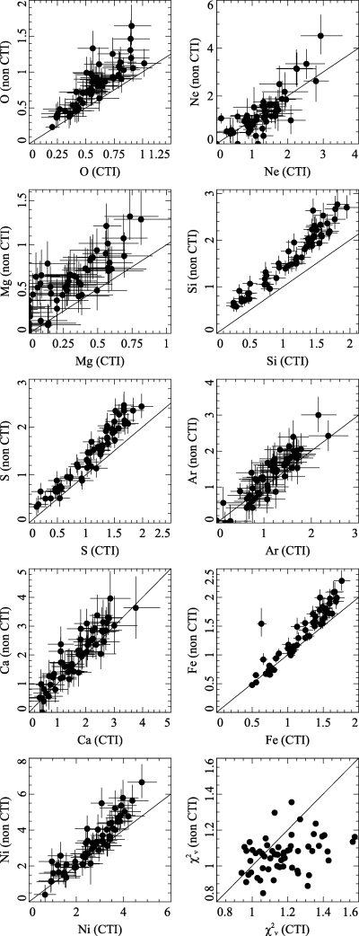
Comparison of abundances obtained using CTI and non-CTI-corrected data, relative to solar. Results shown are using the spex spectral model with one, two or three temperature components. Also shown are the reduced χ2 from the fits for the two data sets.
There are some differences between the results obtained from the two different sets of data. For Fe, at low metallicities (and therefore at comparatively high temperatures of ∼4 keV), there is little difference between the different data sets. At higher metallicities, the use of the uncorrected data produces higher metallicities than the corrected data. More worryingly, some elements also show offsets in their abundances. This difference is most readily apparent in Si, S and O.
It is difficult to assess whether either of the two abundance measurements is correct. We therefore compared the metallicities obtained against those from XMM–Newton data from the same radius in the cluster (see Section 4 for these results). In the central regions, the relatively poor spatial resolution of XMM means that the small-scale temperature variations make abundance determinations more difficult. In addition, the wide point spread function (PSF) moves strong emission from the centre of the cluster to the outskirts. However, we see good agreement between the non-CTI-corrected Chandra and XMM results for the best-determined elements, especially in the outskirts. O is a notable exception. The CTI-corrected data show an offset in Si relative to the XMM results.
We will therefore present results using the standard data preparation tools, and not those using the results of CTI correction. We note, however, that the abundance trends we observe are not removed by the CTI correction. In addition, Si is the only element with strong difference between the CTI-corrected and standard results.
3.4 Maps
In Fig. 4, we map the abundance distributions in each of the fitted elements, using the spex spectral model, with one, two or three temperature components. In Fig. 5, we also plot the values of the abundance measurements in each region against the Fe abundance for the same region. On these plots are also plotted the ratios of the abundances to Fe expected for the W7 Type Ia supernova model (Nomoto et al. 1997b), and a Type II model (Nomoto et al. 1997a). We examine the enrichment by different supernovae types in Section 4.1.
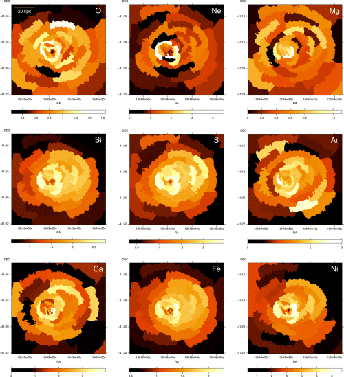
Abundance maps for each of the elements examined. The element maps were generated from spectra containing over 40 000 counts (signal-to-noise ratio of 200). These results were obtained using the vspex spectral model. The statistical errors on these quantities can be found using the scatter plots in Fig. 5. The outer parts of these image appear to the bottom left of these plots, as these are the regions of lowest abundance.
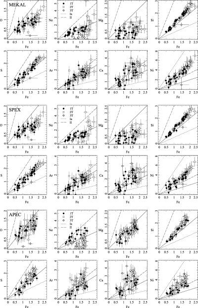
Abundance of individual elements of each spatial region from the 200 signal-to-noise ratio spectral fits, plotted against the iron abundance. The diagonal line shows solar abundance ratios. White points show regions where two temperature models were required, black points show regions where single temperature models were sufficient and grey points show where three components were required. Results using (top) mekal, (centre) spex and (bottom) apec plasma codes. Also plotted are the abundance ratios expected for the W7 Type Ia model (Nomoto et al. 1997b) and a Type II model (Nomoto et al. 1997a).
The region where two temperature components are used is mainly within 80 arcsec radius of the core. Three temperature components are primarily required within the central tail-like feature. It is interesting to note that the third temperature in the inner regions is relatively hot at around 6 keV, with the other two components at 0.7 and 1.5 keV. This may suggest non-thermal or shocked emission is present in this region.
The best determined elements, including Fe, S and S, show extensions to the west of the nucleus. To the west, the metallicities drops rapidly at a radius of 30–40 kpc. This coincides with the rapid rise in temperature (Fig. 6; Fabian et al. 2005).
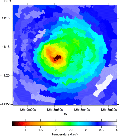
Emission-weighted temperature map, using regions containing at least 10 000 counts.
Their distributions appear quite smooth using these large regions. However, if we bin the data using a minimum signal-to-noise ratio of 100, then we observe quite a large amount of structure (Fig. 7). This includes a ‘plume-like’ feature showing in Fe, Si and S around position 12h48m38.0s, −41°18′ 27″. Curiously, the elements often show enhancements at radii just before they drop, most easily seen to the north-west, at the edge of the high-abundance region. These appear similar in appearance to the high-abundance shell found in the Perseus cluster (Sanders, Fabian & Dunn 2005). In more detail, this spike can be seen in the profile in Fig. 8. Interestingly, the temperature appears to rise across the edge at the radius of the spike, and not after it.
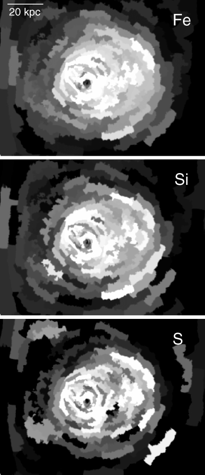
Higher spatial resolution abundance maps of Fe, Si and S, generated using regions containing at least 10 000 counts. Note the high-metallicity plume-like feature embedded in the high-metallicity extension to the west. There also appears to be high-metallicity regions to the edge of the western extension.
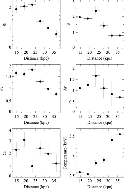
Profile across the edge of the high-abundance region to the NW. There is some evidence for a spike in metallicity just inside the drop in some elements, include Fe, S and Si (third point from the left). Curiously, there is a rise in temperature associated with the radius of the increase. The sectors are centred on the position 12h48m42.9s, −41°18′ 41″, and are between angles  and
and  northwards from the west.
4 PROFILES
To examine in detail the abundance of the elements, we have performed an analysis using two 180° sectors to the east and west of the cluster, as the maps of the cluster show a clear east/west anisotropy in the central region. In addition, we performed spectral fits using 360° sectors from an XMM–Newton observation of the cluster, to examine the abundances at larger radii.
In Fig. 9, we show the Chandra regions used for this spectral analysis. As we analysed several different observations, with different rolling angles and pointings, we used different angular ranges for each data set in the outer parts of the cluster.
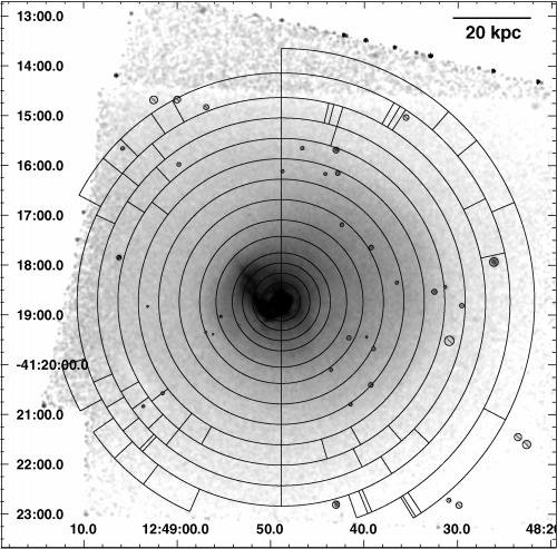
Regions used for the radial profiles in Section 4. Image is an exposure-corrected 0.4–7 keV Chandra image smoothed with a Gaussian of 1.5 arcsec. Point sources are marked with circles with lines across. The radial lines are starting and stopping angles of the regions for individual data sets which were taken with different roll angles.
We used the same spectral fitting procedure as the maps for the profiles. The derived abundances, temperatures and other properties are all emission-weighted, projected results. Fig. 10 depicts the spex model profiles for each element for the east and west sectors, and the XMM results. Fig. 11 contains similar profiles, but using the apec model for comparison. We do not use the mekal model here as we have already shown that it produces very similar results to spex.
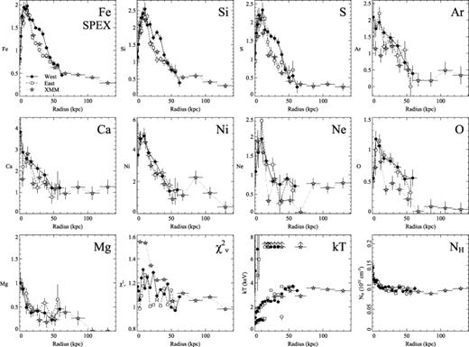
Projected abundance profiles for the west and east of the cluster, generated by fitting with the spex model. An F-test was used in each annulus to decide between 1, 2 and 3 temperature component fits. Shown are the Fe, Si, S, Ar, Ca, Ni, Ne, O and Mg abundances relative to solar. Also shown are the gas temperature components and absorption fitted. If a temperature component is outside of the range shown, an arrow at 7 keV is plotted.
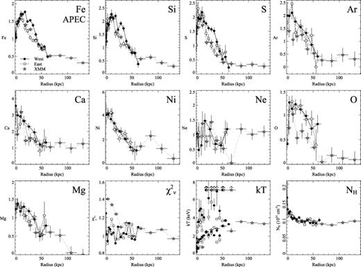
Same as Fig. 10, but using the apec spectral model.
The profiles show that the distribution of each of the metals appears to be highly peaked. As expected, in the inner regions the Fe, Si and S abundances are enhanced to the west of the core compared to the east. This enhancement appears to start at around 40 kpc radius. Within 15 kpc, there is no obvious difference between the two halves of the cluster. These results agree with the two-dimensional results in Section 3.4.
Curiously, there is no obvious difference in the metallicities between the two halves in Ar, Ni, Ne, O and Mg. There may be some enhancement in Ca, however. These metals are harder to determine than Fe, Si and S, but if the results are correct it suggests that the process causing the east–west anisotropy enhances only Fe, Si, S and perhaps Ca. The two-dimensional maps also agree with the profiles.
This can be seen in a plot of the cumulative mass in different elements as a function of radius (Fig. 12). These results assume our projected Chandra metallicities, but were calculated with the deprojected density profile fit of Graham et al. (2006). A base metallicity of 0.3 Z⊙ was subtracted from each metallicity profile. The density profile includes results from Chandra, XMM and ROSAT, going out to larger radii than our Chandra data alone. Also plotted is the cumulative gas mass profile computed from the density profile.
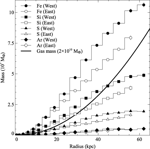
Cumulative mass profiles for the Chandra results in the east and west sectors, for selected metals. Note that most of the metals show more mass to the west, except for Ar here. Also plotted is the cumulative gas mass (in units of 2 × 10¹⁰ M⊙), computed from the hydrogen density profile of Graham et al. (2006).
The gradient in metallicity in the central region, for both the eastern and western halves, shows a steep increase at a radius of about 50–60 kpc. Outside of this radius, the abundance profile is relatively flat. This picture is the same for each of the elements, except Mg which is difficult to measure and differs greatly between the two models.
Fig. 13 shows the Fe metallicity profile compared against the B-band surface brightness and electron density profiles. Both the electron density and optical surface brightness profiles have similar shapes. A comparison of X-ray emission (showing the metal-rich region) and Digitized Sky Survey optical image of the cluster core (Fig. 14) shows that the metals lie over a large region compared to majority of the optical light.
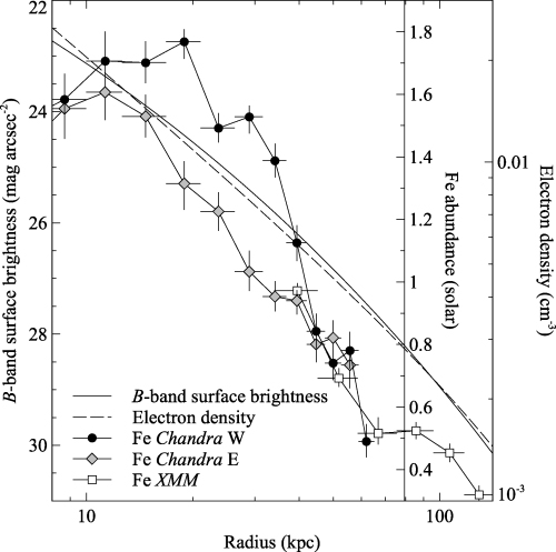
Comparison of the Fe metallicity, the X-ray electron density (Graham et al. 2006) and B-band surface brightness profile (Jerjen & Dressler 1997). The B-band profile was computed using the effective radius (15.4 kpc) and the mean effective surface brightness. We show the east/west Chandra metallicity results in the inner region and the spatially averaged XMM values at large radii.

Left-hand side: accumulatively smoothed (Sanders 2006) X-ray image in the 0.4–7 keV band with the point sources removed. The whole of the shaded region is metal rich. Right-hand side: digitized Sky Survey image of the same area of sky.
4.1 Supernovae model fits
To understand the physical processes behind the enrichment, we have examined the ratios of the abundances of the elements with respect to Fe, to compare to predictions from supernovae yield models. The ratios here are the ratios of the measurements in solar units. Fig. 15 shows the ratios as a function of radius, using the spex and apec models. The Chandra ratios have been binned as pairs to improve the signal-to-noise ratio.

Profiles of the ratios of the solar relative metallicities of each element to Fe, using the spex (top) and apec (bottom) models.
In Table 3, we list the ratios calculated for different supernova models. The Type Ia ratios (models W7, W70, WDD1, WDD2 and WDD3) were calculated using Nomoto et al. (1997b). The Type II ratio was calculated from Nomoto et al. (1997a), integrating over an initial mass function of index 1.35 between 10 and 50 solar masses.
Ratios of elemental abundances in solar units relative to Fe for each SNe model. The Type Ia ratios were calculated for each element for the W7, W70, WDD1, WDD2 and WDD3 models in Nomoto et al. (1997b). The Type II ratios were calculated from the results in Nomoto et al. (1997a), integrating over an initial mass function of index 1.35 between 10 and 50 solar masses.
| Element | W7 | W70 | WDD1 | WDD2 | WDD3 | Type II |
|---|---|---|---|---|---|---|
| O | 0.037 | 0.033 | 0.035 | 0.019 | 0.011 | 2.940 |
| Ne | 0.006 | 0.003 | 0.003 | 0.001 | 0.001 | 2.067 |
| Mg | 0.033 | 0.058 | 0.044 | 0.019 | 0.010 | 2.949 |
| Si | 0.538 | 0.467 | 1.688 | 1.013 | 0.632 | 2.961 |
| S | 0.585 | 0.597 | 1.972 | 1.199 | 0.747 | 1.857 |
| Ar | 0.387 | 0.463 | 1.424 | 0.895 | 0.554 | 1.281 |
| Ca | 0.473 | 0.718 | 2.138 | 1.399 | 0.868 | 1.511 |
| Ni | 4.758 | 3.637 | 1.650 | 1.398 | 1.572 | 1.663 |
Taking an observed ratio for a particular element relative to Fe from Fig. 15, we can compute, assuming a Type Ia model and Type II model, the ratio of Type Ia to II supernovae enrichment. Shown in Fig. 16 are the fractions of the enrichment due to Type Ia supernovae, calculated using the ratio of each element to Fe, as a function of radius. This is the result of solving the equation
for f, where f is the Type Ia fraction, and ZX is the abundance of element X, relative to solar. The two terms on the right-hand side are the predicted Ia and II ratios. Here, we assume the yields of Type Ia supernovae using the W7 model, and the Nomoto et al. (1997a) Type II model.
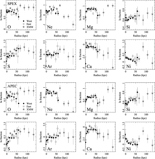
Calculated Type Ia fractions from the ratio of each element to Fe. Top panel shows spex and the bottom shows apec. These results assume the W7 Type Ia abundances, and Nomoto Type II results.
The results show that for the best determined abundances, Si and S, there appears to be a decreasing ratio of Type Ia enrichment within about 50 kpc radius. Ar and O ratios also indicates that this is the case. Ca, however, indicates the opposite, and so does Ni. Ni is a difficult element to determine, however. Ne and Mg also appear to be dependent on the spectral model used. We note that Werner et al. (2006) and de Plaa et al. (2006) find Ca values which disagree with standard nucleosynthesis results for the clusters 2A 0335+096 and Sérsic 159-03, respectively.
5 DISCUSSION
The apec results shown in Fig. 16 provide a reasonably consistent picture from O, Ne, Mg, Si and S in which the Type Ia fraction is about 0.7 ± 0.1, with a possible central drop (within 10 kpc) to 0.5. The remaining results (Ar, Ca and Ni) are from weak or confused (Ni) lines. The spex results are less conclusive but are also broadly consistent with this conclusion. Such a Type Ia fraction is very similar to that found both in the hot interstellar medium of early-type galaxies (Humphrey & Buote 2006) and in the solar neighbourhood.
Our results are therefore consistent with the expected products of normal star formation. This conclusion contrasts with the usual model (Matsushita et al. 2003) discussed for the central iron excess in clusters, which assumes that the excess iron is from Type Ia supernovae alone. Such a Type-Ia-only picture is usually justified by the assumption of no massive star formation in the central galaxy and thus no Type II supernovae, since the last major cluster merger or major disruption. This may be the case for most clusters, but not for central high-abundance objects, like the Centaurus cluster, which have presumably been relatively undisturbed (Graham et al. 2006).
The centre of the Centaurus cluster shows good evidence from X-ray spectra for at least some continued cooling of the innermost hot gas (∼10 M⊙ yr−1; Sanders & Fabian 2002) and has a web of emission-line filaments and dust lanes (Crawford et al. 2005). The central galaxy, NCG 4696, is a giant elliptical, with a de Vaucouleurs profile and no evidence for an extended halo in near-infrared H-band observations (Arnalte Mur, Ellis & Colless 2006). The optical spectral indicator D4000 of the galaxy light is slightly smaller than seen in field ellipticals, which may indicate some excess blue light and thus ongoing star formation (Johnstone, Fabian & Nulsen 1987). The total mass of iron in the high-abundance peak at radii less than 40 kpc is about 1.4 × 10⁸ M⊙ (Fig. 12). If 30 per cent of this is from Type II supernovae which release an average of 0.07 M⊙ per event (Renzini 2004), then 6 × 10⁸ supernovae are required. Each Type II supernova requires a total of about 70 M⊙ of star formation so we deduce a total star-forming mass of 4 × 10¹⁰ M⊙, assuming a normal initial mass function.
A direct consequence of our work is the discovery of the Type II supernova products from a significant episode of star formation in the central cluster galaxy, NGC 4686, of the Centaurus cluster. We now explore three scenarios for this enrichment: (i) continuous star formation, (ii) sporadic activity over the past few Gyr and (iii) a remnant of the formation phase of the galaxy, which we assume to have been about 10 Gyr ago. For the last scenario (iii), we include the possibility that the massive stars giving rise to the Type II products occurred early enough to enrich the lower mass stars which now dominate stellar mass loss in the galaxy.
In order to obtain a limit on the current star formation rate in NGC 4696 (scenario i), we use the Mg2 index, which is reduced by the presence of a young stellar population. (The Hβ index, Trager et al. 2005, would be better but is contaminated here by line emission.) It has been employed by Cardiel, Gorgas & Aragón-Salamanca (1998) to reveal and measure the star formation rate in other Brightest Cluster Galaxies. Mg2 has been measured in NGC 4696 by Gorgas, Efstathiou & Aragón-Salamanca (1990) and by Annibali et al. (2006). There is no simple standard with which to measure star formation departures from, although Gorgas et al. (1990) report a corrected offset of 0.01. We adopt that value as an upper limit and note that metallicity can shift the Mg2 index to higher values (Cardiel et al. 1998); as shown in the present paper, the intracluster medium around NGC 4696 is particularly metal rich. Using the model curves in Cardiel et al. (1998), we then obtain a fractional limit on the V light due to star formation of about 10 per cent and a star formation rate limit of 6 M⊙ yr−1 using MB=−23 for the whole galaxy (Jerjen & Dressler 1997). This assumes continuous star formation over the past 5 Gyr, giving a mass to V-light ratio of 2.4 (Gorgas et al. 1990). This limit is just below the value of 8 M⊙ yr−1 derived from the above star-forming mass assuming star formation spread over 5 Gyr. The values become consistent if the time-scale is increased to 8–10 Gyr. Further factors to consider are that the star formation could have been concentrated to the centre of the galaxy, where there is a large dustlane and other dust features, and that it may have occurred in bursts (scenario ii).
The alternative possibility is to assume that the metal enrichment is a fossil of the formation of the main body of the galaxy (scenario iii). If the Type II products have always been in the intracluster medium, it requires that the central intracluster medium has been largely undisturbed for up to 10 Gyr and constraints on diffusion of metals in the gas (e.g. Graham et al. 2006) become even tighter. The Type II products may, however, have been incorporated in lower mass stars which are now releasing the material through stellar mass loss. To investigate this possibility, we use the work of Ciotti et al. (1991), updated with the values of Pellegrini & Ciotti (2006). Specifically, we increase the stellar mass-loss formula of Ciotti et al. (1991) by 20 per cent to  , where time is measured in units of 10t10 Gyr and LB is the total B-band luminosity of the galaxy (we use LB= 1011 L⊙). The Type Ia supernova rate is taken as RSN= 1.8 × 10⁻¹³LBt−1.110 yr−1. The total stellar mass lost over the past 5 Gyr (8 Gyr) is then 2 × 10¹⁰ M⊙ (6.3 × 10¹⁰ M⊙) with a mean (Type Ia) iron abundance of 1.35 (1.21). If the stars were already enriched by Type II supernova, we then have a plausible explanation for our result in terms of stellar mass loss over the past 8 or more Gyr.
In summary, only part of the effect we find can be explained by continuous star formation. Stellar mass loss must occur and will have contributed much of the gas within the inner 40 kpc radius, where the total gas mass is about 6 × 10¹⁰ M⊙ (Fig. 12). If the mass lost by stars was enriched by Type II supernovae then, together with enrichment by Type Ia supernovae, the gas accumulated over the past 8 Gyr would resemble the medium around NGC 4696. A robust conclusion is that the enriched region has not suffered major disruption in the past 8 Gyr or more.
The evidence for Type II supernova products requires that either star formation has continued at a rate of ∼5 M⊙ yr−1, which should be testable with further optical spectroscopy, or they are a remnant of the original major star formation episode of NGC 4696. The core of the Centaurus cluster must have been in a close heating–cooling balance for the past 8 Gyr or more. Any major cooling or heating episode would have reduced the metallicity peak either by consuming it in star formation or by diluting it if the gas was driven to larger radii.
The authors are grateful to Glenn Morris for his help in making the spectra from the XMM–Newton observation. We thank Luca Ciotti for advice on stellar mass loss and enrichment. ACF thanks the Royal Society for support.
