


Abstract
We evaluated the basic characteristics and efficacy of our newly developed patient fixation system for head and neck radiotherapy that uses a dedicated mouthpiece and dental impression materials. The present investigation demonstrated that with this system, the changes in the absorbed dose to water depending on the material of the mouthpiece were small, with a maximum of 0.32% for a 10-MV photon beam. For the dental impression material, we selected a silicone material with the lowest Hounsfield unit (HU) value that had little effect on the generation of artifacts and the quality of the X-ray beam. Multiphase magnetic resonance imaging (MRI) revealed that the head-up and -down motions in the thermoplastic shell without the mouthpiece were 5.76 ± 1.54 mm, whereas the motion with the mouthpiece decreased significantly to 1.72 ± 0.92 mm (P = 0.006). Similarly, the head-left and -right motion displacement decreased from 6.32 ± 1.86 mm without the mouthpiece to 1.80 ± 0.42 mm with the mouthpiece (P = 0.003). Regarding the tongue depressor function of the mouthpiece, the median distance from the hard palate to the surface of the tongue was 28.42 mm. The present results indicate that the new immobilization device developed herein that uses a mouthpiece and a thermoplastic shell is useful for suppressing patients’ head motions and tongue positions.
INTRODUCTION
In radiotherapy of the head and neck region, fixation with thermoplastic shells is commonly used to suppress the patient’s motion during irradiation and to improve the reproducibility of the treatment position. Indeed, the latest evidence-based publications and guidelines recommend the use of thermoplastic shells for radiotherapy of the head and neck regions [1,2]. However, it is known that even when fixation with a thermoplastic shell is used, set-up errors on the order of millimeters can occur within the shells [3]. Intraoral spacers are frequently used in combination with a thermoplastic shell to decrease the doses to normal tissues by exerting downward pressure on the patient’s tongue. However, intraoral spacers are often made by hand at individual institutions, and in-house spacers have the disadvantage of requiring experience and the necessary amount of time for making the appropriate shape for each patient’s unique needs. In addition, because of the difficulty of breathing through the mouth with spacers, there is a risk of respiratory disturbance in patients with nasal obstruction.
We thus developed a new patient fixation system that uses a dedicated mouthpiece and dental impression materials to solve these problems. We conducted the present study to: (i) evaluate the basic characteristics of the new mouthpiece and dental impression materials, and (ii) determine the system’s tongue depressor functions and its ability to suppress head movements.
MATERIALS AND METHODS
Design of the mouthpiece
In this study, the requirements for the newly developed mouthpiece were as follows: the mouthpiece should: (i) improve the accuracy of patient fixation, (ii) have a function of downward pressure on the tongue, (iii) have a structure that allows breathing through the mouth, (iv) be easy to make for each patient, and (v) should be easy to put on and take off in an emergency. We selected polypropylene (density: 0.90 g/cm3) as the mouthpiece material. Polypropylene is not easily eroded by acids or alkalis and is widely used in medical devices, packaging materials, laboratory equipment, containers, textiles and automotive parts [4]. The shape of the mouthpiece was determined by repeated trial fitting and problem identification. The prototypes of the mouthpiece were made repeatedly by a 3-dimensional (3D) printer using computer-aided design (CAD).
X-ray attenuation of mouthpiece materials
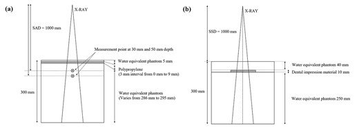
Geometry of the phantom verification. The X-ray attenuation of mouthpiece materials (a) and the effect of dental impression materials on the PDD (b) were evaluated with a water-equivalent phantom. The polypropylene resin sheets were placed 5 mm deep and changed at 3 mm intervals up to 9 mm for each measurement. An ionization chamber was installed at 30 mm depth with the phantom at 50 mm depth for the measurement of the absorbed dose to water. Two types of dental impression materials were molded into 10 mm-thick plates and placed at 40 mm depth in the phantom.
Dental impression materials for use with the mouthpieces
In principle, the newly developed mouthpiece is used in combination with commercially available dental impression materials. The dental impression materials have different Hounsfield unit (HU) values on X-ray computed tomography (CT) images depending on the type of material, and the artifacts generated on the images used for treatment planning may interfere with the contouring of the target volume and organs at risk. In this study, six types of commercially available dental impression materials were imaged using an X-ray CT system (Aquilion LB, Canon, Tokyo), and the HU values of each dental impression material were compared. Table 1 provides a list of the dental impression materials used for comparison.
The dental impression materials (manufacturer, product name and material)
| Mfr. | Name | Material |
|---|---|---|
| GC | Exafine (Putty Type) | Silicon |
| GC | Fusion II (Wash Type) | Silicon |
| GC | Fusion II (Monophase Type) | Silicon |
| GC | Fusion II (Heavy Body Type) | Silicon |
| GC | Aroma Fine Plus | Alginate |
| Pentron | Correct Plus | Silicon |
| Mfr. | Name | Material |
|---|---|---|
| GC | Exafine (Putty Type) | Silicon |
| GC | Fusion II (Wash Type) | Silicon |
| GC | Fusion II (Monophase Type) | Silicon |
| GC | Fusion II (Heavy Body Type) | Silicon |
| GC | Aroma Fine Plus | Alginate |
| Pentron | Correct Plus | Silicon |
GC Corp.: Tokyo. Pentron: Orange, CA, USA.
We also compared the effects of the different HU values of the dental impression materials on the treatment planning X-ray beam quality. Two types of silicone dental impression materials were selected for comparison: one with the lowest HU and the other with the same HU as the bone material. We compared the differences in the percentage-depth-dose (PDD) of the photon beams by using CT images of water-equivalent phantoms containing two types of 10-mm-thick dental impression materials that were calculated by the treatment planning system (Eclipse ver. 11.0.47, Varian Medical Systems, Palo Alto, CA, USA). The calculation algorithm was AAA ver. 11.0.31, and the calculation grid size was 1.0 mm. The planning conditions were the standard measurement conditions (field size 100 × 100 mm2, 200 MU and source-surface-distance [SSD] 1000 mm), and the photon energy for comparison was a 4-MV photon beam. Two types of dental impression materials, i.e. Exafine Putty type (GC, Tokyo) and Fusion II Wash (GC), were used for comparison. The arrangement of the dental impression materials in the phantom used for comparison is shown in Fig. 1b.
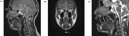
The anatomical structures in the head motion and tongue depressor measurement. The displacement indices were the maximum displacement (distance B) at the facial surface due to the head-up and -down motion and the maximum displacement (distance C) at the midline due to the head-left and -right motion. For the evaluation of the tongue depressor function, the distances from the hard palate to the apex of the tongue (distance D), from the hard palate to the anterior part of the dorsal surface of the tongue (distance E), from the hard palate to the posterior part of the dorsal surface of the tongue (distance F) and from the posterior pharyngeal wall to the root of the tongue at the uvula tip (distance G) were measured, respectively.
Evaluation of head motion suppression function by MRI
The gripping part of the mouthpiece is designed to be integrated with the thermoplastic shell in order to suppress the patient’s head motion inside the fixation device. To investigate the difference in head motion inside the thermoplastic shell with and without a mouthpiece, we compared the head positions during forced head motion (head-up and head-down motion, head-left and head-right motion) associated with verbal instructions during multiphase magnetic resonance imaging (MRI) using fixation by the thermoplastic shell with or without a mouthpiece.
The evaluations of head motion and the tongue depressor function were performed using MRI sagittal and coronal images. Figure 2 shows the anatomical structures used as indices for displacement measurement. For the evaluation of head-up and -down motions (Fig. 2a), we measured the distance (B) at the facial surface between the line connecting the nasal bone and the dorsum sellae for the head-up motion (line A) and the line connecting the nasal bone and the dorsum sellae for the head-down motion (line A).
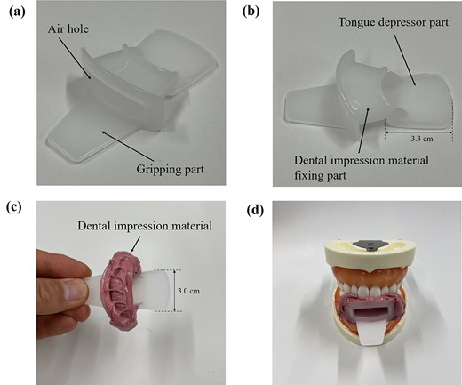
Structures and function of the developed mouthpiece for radiotherapy. The mouthpiece consists of a gripping part, an impression material-fixing part and a tongue depressor part (a, b). An example of a tooth mold made using the mouthpiece and dental impression material is shown (c, d).
For the evaluation of the head-left and -right motions (Fig. 2b), we measured the change in distance (C) between the midline for the head-left and head-right motion. MRI was performed with a Discovery MR750w 3.0 T MR system (GE Healthcare, WI, USA) using a body coil to obtain sagittal and coronal T2 images centered on the maxillary region. Displacement measurements were performed using the Image J program (ver. 1.37, US. National Institutes of Health). For head fixation, a 2.4-mm-thick thermoplastic shell (U-Frame, Klarity Medical Products, Newark, OH) was used with a urethane pillow and a carbon fiber base plate (MT20100CF, CIVCO Medical Solutions, Riverside, IA). This examination was conducted with five healthy adult volunteers after we obtained study approval from the Clinical Research Ethics Review Board of our institution. The head motion suppression function of the mouthpiece was evaluated from the measurement data obtained with and without the mouthpiece using the corresponding t-test. A P-value <0.05 was considered significant. The statistical analysis software used was IBM SPSS Statistics ver. 26.
Evaluation of tongue depressor function of mouthpiece by MRI
To evaluate the tongue depressor function of the mouthpiece, MRI T2 sagittal images were taken and the distances between the surface of the tongue and several intraoral anatomical landmarks were measured (Fig. 2c).
RESULTS
Design of mouthpiece
The structure of the mouthpiece developed in this study is shown in Fig. 3. The mouthpiece consists of a gripping part for wearing, a dental impression material-fixing part and a tongue depressor part. The mouthpiece is designed to improve the reproducibility of the fitting because it can be used to make individual tooth shapes for each patient based on the patient’s dental impressions. The convex structure of the dental impression material-fixing part is expected to make it easy for the impression material to adhere to the mouthpiece. The air hole in the center of the mouthpiece allows the patient to breathe through the mouth and vocalize in an emergency. The thickness of the main body of the mouthpiece was designed to be the minimum possible thickness for the purpose of tongue compression and to prevent difficulty in wearing the mouthpiece due to mouth-opening restrictions that may occur during treatment.
The mouthpiece can also be flipped 180° to create more space in the mouth when tongue depression is not needed. An example of the use of the mouthpiece with and without tongue depression is shown in Figs 4a and b.
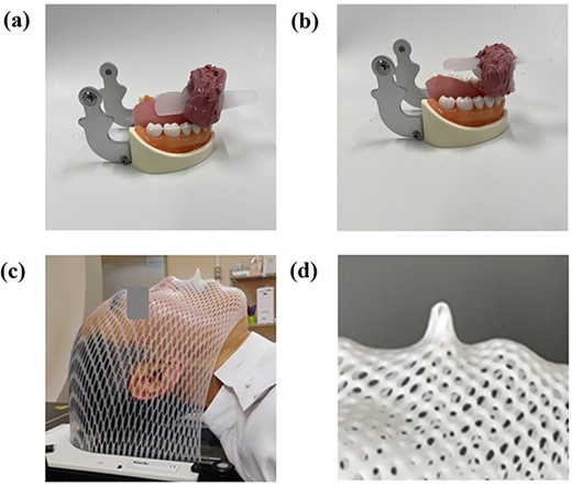
Tongue depressor function of the mouthpiece and fixation with a thermoplastic shell. If tongue depression is needed, the tongue can be pushed out caudally (a). If tongue depression is not needed, the mouthpiece can be flipped over (b). The mouthpiece is combined with a thermoplastic shell using the gripping part of the mouthpiece (c, d).
The mouthpiece is designed to improve the reproducibility of patient fixation accuracy because the mouthpiece gripping part and the thermoplastic shell are integrated into a single structure (Figs 4c and d).
X-ray attenuation of mouthpiece materials
Figure 5 shows the effect of the polypropylene sheet thickness on X-ray attenuation in a water-equivalent phantom. Regardless of the thickness of the polypropylene sheet, the change in the relative dose was small, with a maximum of 0.32% at a measurement depth of 5 cm with the 10-MV photon beam.
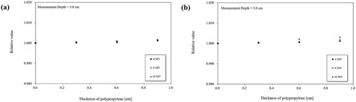
X-ray attenuation due to differences in the mouthpiece material’s thickness. The measurement results are shown at 30 mm depth (a) and 50 mm depth (b). Results for the 4 MV (●), 6 MV (×) and 10 MV (▲) beams are shown. Each value is normalized to the absorbed dose to water without the mouthpiece material.
Dental impression materials for use with the mouthpieces
The CT images and HU values of the dental impression materials are shown in Fig. 6. The HU values of the alginate material were lower than those of the silicon material (Fig. 6a). The HU values of the same silicone material differed depending on the type. Artifacts caused by the dental impression material were strongly observed in the Collect Plus material (Fig. 6c), which had the highest HU value. The effects of dental impression materials on the X-ray beam quality are depicted in Fig. 7, which compares the PDD changes of the dental impression materials. The maximum dose change for the Exafine Putty type was −2.90%, while that for the Fusion II Wash was less at −0.94%.
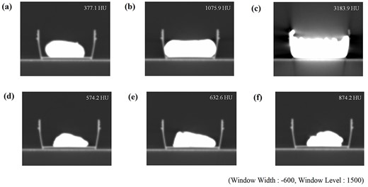
Dental impression materials and HU values. The numbers in the figure indicate the HU values. The windowing condition was set to a constant value (window level: 1500, window width: −600). (a) Aroma Fine Plus, (b) Exafine (Putty type), (c) Correct Plus, (d) Fusion II (Wash type), (e) Fusion II (Monophase type) and (f) Fusion II (Heavy Body type).
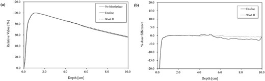
The effect of different dental impression materials on the PDD. The PDD for each dental impression material are plotted at 1-mm intervals mm from the surface to 100 mm depth (a). The changes in the value relative to the case without the use of impression material were normalized to the maximum depth dose (b).
Evaluation of head motion suppression function by MRI
Figure 8 illustrates the effect of the mouthpiece on the head motion inside the fixture by a thermoplastic shell measured by MRI. The displacement inside the thermoplastic shell due to forced head-up and -down motion by verbal instructions was 5.76 ± 1.54 mm without the mouthpiece and significantly less with the mouthpiece, at 1.72 ± 0.92 mm (P = 0.006). Similarly, the displacement inside the thermoplastic shell due to the head-left and -right motion was 6.32 ± 1.86 mm without the mouthpiece and significantly less with the mouthpiece, at 1.80 ± 0.42 mm (P = 0.003).
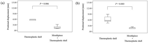
The effect of the mouthpiece on the head motion inside the fixture by a thermoplastic shell. The position displacements due to head-up and -down motion (a) and due to head-left and -right motion (b) with and without the mouthpiece are shown. The numbers in the figure indicate significant differences calculated by statistical analysis.
Evaluation of tongue depressor function of mouthpiece by MRI
The tongue depressor function of the mouthpiece were measured on MRI sagittal images, and the mean distance (D) from the hard palate to the apex of the tongue was 25.50 mm with the mouthpiece (range 18.26–32.74 mm), distance (E) from the hard palate to the anterior part of the dorsal surface of the tongue was 28.42 mm (range 24.16–34.59 mm), distance (F) from the hard palate to the posterior part of the dorsal surface of the tongue was 13.54 mm (range 11.67–15.41 mm), distance (G) from the posterior pharyngeal wall to the root of the tongue at the uvula tip was 12.81 mm (range 10.32-15.24 mm), respectively (Fig. 2c). In all cases, the root of the tongue was in contact with the soft palate.
DISCUSSION
There have been several reports on the effectiveness of intraoral spacers in radiotherapy. Hollows et al. reported that the use of intraoral spacers made using maxillofacial prosthetic technology in oral radiotherapy reduced the dose to normal tissues around the treatment site, reduced the rate of the early adverse events of mucositis and improved the patients’ oral comfort and eating [6]; in addition, the risk of late adverse events such as radiation caries and osteonecrosis was reduced, leading to the maintenance of the patients’ quality of life [6]. In recent years, mouthpiece-type intraoral spacers created with 3D printers have been reported. Huang et al. demonstrated that the use of a silicone mouthpiece created by a 3D printer based on CT image data for the treatment planning of head and neck radiotherapy provided good occlusal-plane congruence and tongue fixation without inducing oral reflexes, resulting in dose reduction in normal tissues [7].
Mouthpiece-type intraoral spacers with or without dental impression material have been available as commercial products; e.g. PreciseBite (CIVCO Medical Solutions) and BiteLok™ (Klarity Medical Products). Some of these spacers can be fixed with dental molds and integrated with thermoplastic shells, but they are not versatile enough to cope with adaptive cases or changes in the oral environment during treatment.
In several reports using mouthpieces, original in-house mouthpieces were made for each case [5,6]. The mouthpiece designed in the present study is highly versatile and can be easily customized for each patient by using the patient’s dental impression materials. Our new mouthpiece also has a simple structure with no parts, and it is thus easy to handle even for inexperienced users. Depending on the case, additional impression material can be adhered to the side of the mouthpiece, which is useful for lateral compression of the tongue. The gripping part of the mouthpiece is designed to be integrated with the thermoplastic shell, which can reduce intra-fractional set-up errors by suppressing the movement when the patient wears the thermoplastic shell. The gripping part of the mouthpiece acts as a guide when the shell is attached, which is thought to reduce inter-fractional set-up errors. The new mouthpiece can be easily attached and removed in an emergency because the gripping part of the mouthpiece and shell are fixed by simply attaching the thermoplastic shell, whereas commercially available mouthpieces must be fixed with clips and other parts. The air hole in the center of the mouthpiece not only allows patients to breathe through their mouths and vocalize in emergencies but also provides a route for vomit to escape if a patient vomits while wearing the mouthpiece.
The purpose of using a fixation device in radiotherapy is to maintain a stable treatment position and to ensure reproducibility of the treatment position each time. However, even if the fixation device has excellent fixation accuracy, it cannot be considered an optimal fixation device if a sufficient dose cannot be administered due to X-ray attenuation by the fixation device itself. We evaluated the effect of the X-ray attenuation of the mouthpiece material for three different photon beams (4, 6 and 10 MV) in the present investigation and observed that the relative value of the absorbed dose to water by the mouthpiece material was 0.32% at a measurement depth of 50 mm for the 10-MV photon beam. Considering that the specific gravity of polypropylene is only slightly different from that of water, the influence of the mouthpiece material on the X-ray attenuation is small.
Dental impression materials are frequently used to make dental molds for mouthpieces and oral spacers in head and neck radiotherapy. Dental impression materials made of agar, alginate and silicone are commonly used. We compared the artifacts and differences in HU values on CT images of several commercially available dental impression materials herein. The results revealed that an alginate material had the lowest HU value at 377.1 HU. However, dental impression materials made of alginate are not as hard as those made of silicon because they contain a high amount of water during preparation. On the other hand, silicone dental impression materials are known to take impressions with high reliability [8]. Our present findings demonstrated that the HU values of silicon material varied widely from 574.2 HU to 3183.9 HU.
We next compared the changes in the PDD of the 4-MV photon beam incident on a water-equivalent phantom with a plate of dental impression material placed inside in the treatment planning system. The PDD curves of the rear surfaces of the dental impression material varied from −0.94% to −2.90%. The dose-calculation algorithm that we used in this study is known to cause calculation errors in high-density regions such as bones and metals [9]. It should be noted that the presence of high-density materials not only causes uncertainty about the HU value due to artifacts but also contributes to dose calculation uncertainty in the calculation algorithm. We therefore decided to use the silicon material with the lowest HU value in our new fixation system (Fig. 6d).
The International Atomic Energy Agency (IAEA) Human Health Series report 31 described the uncertainty of treatment position set-ups for various patient fixation systems used in radiotherapy, comparing each anatomical region. The uncertainty values of the treatment position for head and neck radiotherapy using thermoplastic shells are approx. 2.0 mm and 3.0 mm, respectively [10]. It has been reported that the combination of a mouthpiece and a thermoplastic shell can improve the reproducibility of treatment position set-up accuracy; Tryggestad et al. compared several patient fixation systems in combination and found that the inter-fractional set-up error of the mouthpiece-thermoplastic shell combination was minimal at 2.1 ± 1.0 mm, making it useful in stereotactic radiotherapy (SRT) where treatment position set-up accuracy is required [11]. Willner et al. conducted a prospective study on the set-up accuracy of radiotherapy in the head and neck region using a fixation system with a bite block and head and neck support. Their results showed that the maximum set-up error was 3.1 mm, and the use of bite blocks was useful for improving the set-up accuracy and reproducibility of accurate treatment positions [12]. Doi et al. analyzed the positional matching data of set-ups based on skin marks or thermoplastic shell marks and those based on cone beam CT for the usefulness of an intraoral mouthpiece in intensity modulated radiotherapy (IMRT) of the head and neck region. They reported that the set-up error was as small as 2.42 mm, and they concluded that the use of intraoral spacers was useful in reducing random and systematic errors in set-up [13].
In the present study, we evaluated how well the combination of a mouthpiece’s gripping part and a thermoplastic shell suppressed the patient’s head motion inside the fixation device under the verbal instructions of head motion. This is a different condition from actual radiotherapy and from previous reports on the use of intraoral spacers. However, our results demonstrated that the fixation accuracy with the mouthpiece was sufficient even for intentionally generated head motion. The use of a fixation system that combines the new mouthpiece and a thermoplastic shell will lead to a reduction in intra-fractional set-up errors during actual radiotherapy.
It has been noted that in radiotherapy of the head and neck region, it is necessary to reduce the dose to the organ at risk in the oral cavity and to reduce the risk of side effects, which is also important from the viewpoint of improving patients’ quality of life [14–17]. Thus, reducing the oral-tissue side effects that occur during radiotherapy is of great benefit to patients. Our present findings revealed that the mouthpiece was able to create a distance of approx. 28 mm from the hard palate to the anterior part of the dorsal surface of the tongue. In radiotherapy of the maxillary and sinus regions, the oral cavity may be included in the high-dose region. Even in such cases, the use of this mouthpiece can maintain the distance between the treatment site and the tongue surface, leading to a dose reduction in the organ at risk. However, the root of the tongue and the soft palate were in contact in all cases, and the distance from the posterior pharyngeal wall to the root of the tongue was not changed with or without the mouthpiece (data not shown). This mouthpiece does not provide spacing ability in these areas.
We believe that our fixation system in this study is useful as a tongue depressor, in particular, in the radiotherapy of tongue cancer or maxillary sinus cancer. Our system may be also useful for improving the fixation accuracy by integrating the gripping part and the thermoplastic shell in patients with brain tumor or head and neck cancer. However, in some cases, the tongue depressor function of the mouthpiece in this study may not be sufficient in the areas around the soft palate or the posterior pharyngeal wall, and this should be carefully considered in the treatment of nasopharyngeal or mesopharyngeal tumors.
CONCLUSION
We evaluated the basic characteristics of our newly developed patient fixation system that uses a dedicated mouthpiece and dental impression materials. The results of the evaluations indicate that our new system can reduce the problems faced in head and neck radiotherapy with or without the use of intraoral spacers. We are now evaluating the efficacy of our fixation system in actual clinical treatment. The results will be published in the near future.
ACKNOWLEDGMENTS
We are grateful to the staff at the Department of Radiology, Hamamatsu University Hospital and for the cooperation of our research partner, Shoda Techtron Corp. (Hamamatsu, Japan).
CONFLICT OF INTEREST
The development of the mouthpiece used in this study was supported from Engineering System Corp. (Matsumoto, Nagano, Japan) and SHODA TECHTRON Corp. (Hamamatsu, Japan). However, both companies are not directly involved in this research.
FUNDING
We have nothing to declare for this research.
PRESSNTATION AT A CONFERENCE
This research was reported at the 34th Annual Meeting of the Japanese Society for Radiation Oncology.
CONTRIBUTION STATEMENT
Masataka Sakamoto devised the research, performed analysis and interpretation of data and drafted the manuscript, supported by Katsumasa Nakamura. Kenta Konishi, Masanori Hirata, Keiichi Ohira, Kohei Wakabayashi, Shuhei Aramaki, Ryou Kokubo and Katsumasa Nakamura were involved in the research design and contributed significantly to the editing of the manuscript. All authors read and approved the final manuscript.
CLINICAL TRIAL REGISTRATION
This research was approved the Institutional Review Board of the Hamamatsu University School of Medicine on 12 October 2020. The research was registered with the University Hospital Medical Information Network Clinical Trials Registry (UMIN000048972; http://www.umin.ac.jp/ctr).
References
Ang KK, Garden AS.
Chao KSC, Perez CA, Brady LW.
