


Abstract
This paper presents a feasibility study of a low-energy consumption ground source cooling system based on a periodic two-phase thermosyphon (PTPT) device in which a condensate is periodically transferred back to the evaporator. Operation of the PTPT is passive with the ground condenser positioned 1–11 m below the evaporator. The ground condenser may be at the condensing temperatures of 12–20°C depending on the ground depth. A semi-analytical approach is used to simulate the transient behaviour of the PTPT device. The simulation aims to study the effect of several parameters on the cooling rate of the device, including the length of condensing coil, the ground depth, the temperatures of the soil and the indoor air. The preliminary simulation results indicate that the PTPT device may be promising for ground source cooling applications.
1 INTRODUCTION
Modern society has an increasing dependence on heating, ventilation and air conditioning (HVAC) systems. However, HVAC systems are energy intensive. It is known that the sector of buildings accounts for a large percentage of the total energy consumption in developed countries such as Italy and the UK and this is responsible for large quantities of CO2 emissions to the atmosphere. The effect of CO2 emissions on the environment in terms of global warming is a pressing matter of international concern. The European Union promises at least 20% reduction in CO2 emissions by the year 2020 from 1990 levels and the UK government sets an ambitious target of 60% reduction in CO2 emissions by 2050. To meet these targets, the primary approach is to extensively use renewable energy sources such as solar energy and geothermal energy. The relatively stable temperature of the ground allows utilization of natural cooling or heating for buildings. The ground source heat pumps are mainly used for the winter period, but their ground source condensers could be used for natural cooling in the summer period. A research report has shown the potential of ground source cooling for an office building [1]. A new integrated system with cooling storage in the soil is also studied [2].
In ground source cooling and heating applications, a water pump circulation system is usually used to transport heat. Li et al. [3] presented an experimental study of a passive direct ground source cooling system for cold areas in China. It consists of a water cooled fan coil inside a room and a borehole-type ground heat exchanger (GHE). The GHE was a U-pipe of 32.5 mm diameter and at the 50 m ground depth. With a circulation flow rate of 0.67m3/h this system was able to maintain the room temperature at ∼26°C for 25 days of continuous operative regime with a cooling rate of ∼950 W. However, this system needs an electrical pump (61 W) and the capital and running costs can be high when it is used for large and distant heat transfer.
It would be therefore attractive to apply a passive heat transfer device in such applications. Several studies have shown the possibility of using a two-phase thermosyphon device combined with GHEs for different applications [4–7]. Thermosyphons, also known as wickless heat pipes, are common passive two-phase heat transfer devices capable of handling large heat fluxes over long distances. Return of the condensate in a heat pipe may be gravity assisted or capillary pumped using a wick structure. However, the conventional capillary-pumped heat pipes (single or loop) can operate against gravity, but have difficulty in handling downward heat transfer over several metres because the capillary force needs to overcome a hydrostatic liquid head of several metres to return the condensate to the evaporator. In the last few years, the wickless thermosyphon devices that are able to operate against gravity have been proposed and studied. Among these are low-frequency periodic two-phase thermosyphon (PTPT), which consists of an evaporator, a condenser and a condensate accumulator. These elements are interconnected and constitute a loop. A prototype PTPT device has been experimented in the past with dielectric fluids at the Department of Energetic of Pisa University. The device has shown a thermal resistance of ∼0.03–0.05 K/W, a temperature oscillation of 5°C and a heat transfer of up to 1000 W at a hydrostatic head of 2 m [5].
This paper presents a preliminary study on the feasibility of using a PTPT heat transfer device for low-energy consumption ground source cooling applications. A ground source PTPT system is a semi-passive device suitable for cooling applications in different buildings such as small rooms, box offices and small houses in the rural region. Other interesting applications could be as an air pre-cooler for direct evaporative cooling system [8] or regenerative evaporative cooling [9]. Although a schematic prototype design is presented in this paper, the main aim of the work is to analyse the technical performance of this device as an innovative semi-passive cooling system.
2 BASIC CONFIGURATION
A generic PTPT consists of an evaporator, a condenser placed in a lower position and an accumulation chamber (AC) or accumulator. The evaporator and the accumulator are periodically disconnected by valves, which can be passively or electrically activated. The operating principle of a PTPT device is described in details previously [5, 10]. This paper presents utilization of the PTPT device for passive ground source cooling of a single-room house during the summer period. In such a case, the PTPT evaporator is placed inside the room and the condenser is horizontally placed in the ground. In this application, the condenser is positioned below the evaporator. A schematic of the system is shown in Figure 1. The ground condenser may operate at the condensing temperatures of 12.5–10°C depending on the ground depth. The accumulator is placed in the room together with the evaporator. The evaporator and the accumulator are periodically disconnected by two electromagnetic valves.
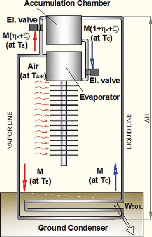
Schematic structure of a PTPT system.
Figure 2 shows the cross-sectional view of a vertical evaporator in a prototype PTPT ground source cooling system. The PTPT evaporator consists of a tank with a volume of 19 l (0.14 × 0.095 × 1.47 m) and 12 vertical aluminium pipes of 0.9 m high. These pipes are finned with 147 rectangular aluminium fins which are 6 mm interspaced and 1.2 mm thick. The room air at the temperature TAIR is drawn by two tangential fans into the evaporator to flow through the fins, as shown in Figure 3. It was assumed that the tangential fans have a volumetric flow rate of 540 m3/h and an electrical consumption of 48 W. This gave an air velocity of 0.15 m/s between the fins and a heat transfer coefficient of ∼9.5 W/m2 K. In such conditions, the fin efficiency is ∼0.83.
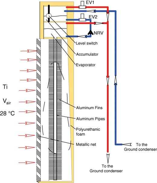
Vertical sketch of the PTPT evaporator.
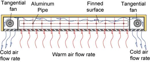
The bottom view of the PTPT evaporator.
It was also assumed that the accumulator has a volume of 19l and it is placed 0.15 m above the evaporator. It is made of aluminium and thermally isolated with a polyurethane foam. Inside the accumulator a level gauge activates the two electrovalves: when the accumulator is full, the electrovalves are opened (transport operation time); when the accumulator is empty, the electrovalves are closed (return operation time).
3 MATHEMATICAL MODEL
In the numerical simulation of a ground source PTPT device, both an accurate prediction of the working fluid dynamical evolution inside the PTPT loop and a seasonable analysis of the device are desired. In the past Filippeschi has set up a mathematical model based on a first time-dependent model proposed by Sasin et al. [11] and rearranged it, tested and experimentally validated [12]. This mathematical model divides the PTPT loop into eight control volumes where the vapour and the liquid were physically separated and a lumped capacitance method was used. For each volume, 16 non-linear differential equations of the mass, momentum and energy balance have been written. The time-dependent equations have been solved in the past with a first-order explicit Euler method. To obtain a good convergence of solution, the time step chosen for the simulation was very short (∼10−5 s) and the prediction errors have been very low [12]. In comparison with the experimental data, these models have shown low prediction errors for the main operating parameters [5].
However, this kind of model is not suitable for simulation of a PTPT over a long period of operation (weeks or months) because of the long computing time. A different approach was presented by Neeper [13] to simulate the long-term behaviour of passive vapour transport solar systems with a semi-analytical model. He determined the main parameters that are involved in the heat transfer downward as the average values related to a whole time period. Neeper proposed an analysis of a PTPT thermal performance by considering the whole system as operating in only two equilibrium states at a steady-state regime. The Neeper model is a steady state.
The simulation code presented in this paper was based on Neeper's model, but with a further assumption: it assumes that each single heat transport cycle is characterized by constant parameters, but these parameters can change over time. Each time step is the period of a whole heat transfer cycle.
Although the cooling process simulation should involve the study of the circulation of the air inside the room and the dynamic behaviour of the PTPT system, this mathematical model assumes that the evaporator is heated by warm air at constant temperature TAIR, and the condenser is cooled by the soil at constant temperature TSOIL. Further analysis could improve this approximated model by including also the evolution of the room air temperature.
The main assumption of this model is that, for each time step, the PTPT operates between two different temperatures: TE which represents the average evaporation temperature of the working fluid in the evaporator and TC the average condensation temperature of the condenser and the accumulator.
To evaluate the temperature of the evaporator and the condenser for each cycle the following considerations were made.
This set of equations was solved using Matlab© platform.
This semi-approximated model therefore is able to simulate a PTPT over time with low computing time, but a validation of the code must be made. The prediction errors of the code have been evaluated by comparing the numerical data with the experimental data obtained with the PTPT device tested by Fantozzi and Filippeschi [10]. The experimental activity was carried out on a PTPT device with HCFC 141b as the working fluid. The heat input to the evaporator was in the range of 100–1100 W. The heat transfer equations (4) and (9)–(10) which are referred to the evaporator and the condenser was modified to match the experimental condition.
Figure 4 shows a comparison between the experimental and numerical evolutions over time of the evaporator and condenser temperatures for two different input powers, 300 and 600 W. Figure 4 shows a good accordance about the evaporator temperature, but a lower accordance about the condenser temperature: this discrepancy increases as the input power increases. This discrepancy is mainly due to heat transfer correlation used to simulate condensation and sub-cooling regime in the heat exchanger at lower temperature. The prediction errors however are <20% as shown in Figures 5 and 6, which give the comparison of numerical and experimental values of the evaporator and condenser temperatures, respectively.
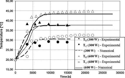
Comparison between numerical and experimental start-up for 300 and 600 W.
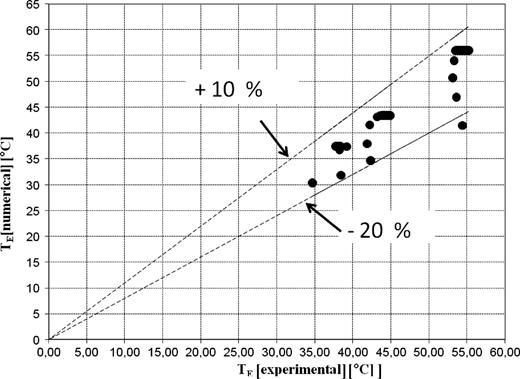
Prediction errors on the temperature of the evaporator.
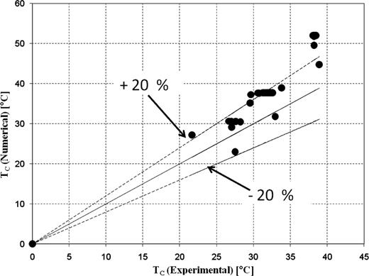
Prediction errors on the temperature of the condenser.
4 NUMERICAL SIMULATION AND RESULTS
The main aim of the numerical analysis is to study the effect on the cooling rate transferred from the air to the soil. The external parameters which can influence the cooling rate WH are mainly the temperature of the air, the temperature of the soil and the ground depth of the horizontal condenser H.
The temperature of the room air was varied from 32 to 25°C in simulations, but it was considered to be constant for each individual simulation. Even if this assumption is not realistic, it allows the PTPT performance to be easily simulated and the length of the GHE to be sized, without taking into account any characteristics of the room. The shallow depth of the horizontal condenser may be chosen on the basis of the soil temperature. In moderate climates and in most technical applications, the available ground temperature level corresponds approximately to the annual average air temperature until a certain ground depth limit. For depths beyond this limit, the ground temperature decreases with depth and, for depths lower than this limit, the temperature increase up to the air temperature at the ground surface. A semi-analytical model to predict the ground temperature has been presented by Droulia et al. [15]. The ground temperature in Italy in the summer period can approximately be estimated at 20°C at 0.5–1 m ground depth.
The minimum depth where the temperature is not influenced by the external climate depends on the characteristics of the soil. It can be ∼4 m for dry sand or dry ground, and it can be 7 m for rocks and compact ground. In this study, the condenser was placed 1–7 m below the evaporator. The ground condenser may operate at the condensing temperatures of 12.5–10°C at 7 m and at the condensing temperatures of 20°C at 1 m. The numerical simulation of the operation of this device was carried out by considering two different operating soil temperatures such as 12 and 20°C. For each soil temperature, the effects of different parameters on the cooling rate were studied. The parameters included the condensation coil length, the temperature of the room air and the mass of the fluid which is circulated in the cycle.
In the reference case, the ground condenser consists of a horizontal tube embedded in the soil. This feasibility study can easily be adapted for condensers in different ground sources such as greywater tank or well. In those cases, the heat transfer is better than the soil, and the same operating conditions can be used with more compact condensers.
The working fluid used in this simulation should be chosen in order to minimize the difference in the temperature, TE− TC. Table 1 shows the values of the combined physical properties of different refrigerant fluids which appear in Eq. (3). When the temperature TE decreases, the combined parameter given in Table 1 increases. The best fluid for a PTPT which operates between TC (12°C) and the value of TE given in Table 1 is the ammonia, because high anti-gravity heights can be pumped.
Physical properties of different refrigerant fluids concerning with the against gravity performances.
| TE (°C) | Ammonia, ρl/(Δp/ΔT), ×106 (K s2/m2) | CO2, ρl/(Δp/ΔT), ×106 (K s2/m2) | R-410A, ρl/(Δp/ΔT), ×106 (K s2/m2) |
|---|---|---|---|
| 20 | 24.37 | 6.23 | 1.50 |
| 24 | 21.78 | 5.62 | 1.62 |
| 26 | 21.23 | 5.27 | 1.69 |
| 28 | 20.69 | 4.86 | 1.74 |
| 31.06 | 19.67 | 3.49 | 1.88 |
| TE (°C) | Ammonia, ρl/(Δp/ΔT), ×106 (K s2/m2) | CO2, ρl/(Δp/ΔT), ×106 (K s2/m2) | R-410A, ρl/(Δp/ΔT), ×106 (K s2/m2) |
|---|---|---|---|
| 20 | 24.37 | 6.23 | 1.50 |
| 24 | 21.78 | 5.62 | 1.62 |
| 26 | 21.23 | 5.27 | 1.69 |
| 28 | 20.69 | 4.86 | 1.74 |
| 31.06 | 19.67 | 3.49 | 1.88 |
For the first reference case, the room temperature was 28°C and the temperature of soil was 12°C. The ground condenser was placed at the depth of 7 m. Figure 7 shows that the cooling rate transferred to the ground increases with an increase in the length of the ground condenser coil. A cooling rate of 750 W is dissipated in the soil with a condenser length of 95 m. The diameter of the pipes of the heat exchanger had only a small influence on the cooling rate. Furthermore, Figure 7 shows that the device can quickly reach a steady state when the condenser length increases. The PTPT which operates with a condenser length of 95 m may need a few days to reach a steady cooling rate of 800 W and after ∼1 month the cooling rate became 780 W.
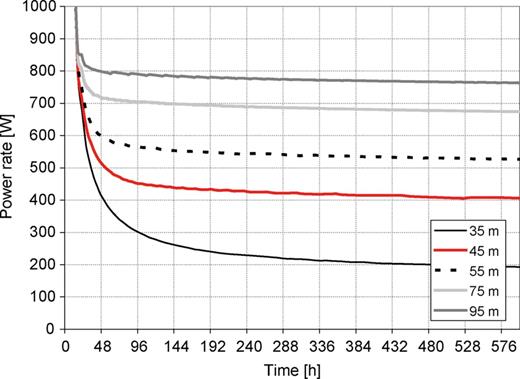
Change of WH with the length of the ground condenser (TSOIL= 12°C, TAIR= 28°C).
The performances of the PTPT ground source system is much influenced by the ground depth and the filling amount of the working fluid. The filling amount of the fluid inside the evaporator is the mass which periodically is transported in the loop.
Figure 8 shows that the heat rate transferred to the soil linearly decreases as the depth increases. For example, at a depth of 5 m, the cooling rate varies from 400 to 980 W when TAIR varies from 25 to 32°C. The capability of the PTPT device transferring heat to the ground is influenced by the temperature TAIR. At 25°C, the device is not able to operate for depths >9 m. This kind of device could be, therefore, applied to small domestic buildings or other compact volumes.

WH at a periodic regime on the dependence of TAIR and ΔH (TSOIL= 12°C, LGHE= 55 m).
Another important technical parameter is the period of a single heat transport cycle. It can be affected by filling amount of liquid and by the difference between the temperatures of the evaporator and the soil. Figure 9 shows that it can varies from 7000 to 42 000 s (2–11h) if the indoor air temperature varies from 25 to 32°C.
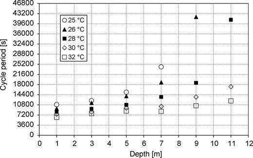
Change in the cycle period of the PTPT with TAIR and ΔH (LGHE= 55 m).
The effect of the filling amount is shown in Figure 10, where a GHE of 95 m long is simulated. The temperatures of the soil and air are 12 and 28°C, respectively. It can be seen that, as the filling amount of fluid increases, the dynamic response of the system is slower. It is important to remember that the energy consumption of activation valves is connected with the period of the cycle, and increases as the period decreases. At the end of each cycle, the valves were activated in order to allow the return of the liquid from the accumulator to the evaporator. This period usually lasts a few minutes [5]. If no fan is used along with the evaporator, the electrical energy consumption was estimated <1 kW h per year to operate the valves in all the studied configurations. If fans are used in the evaporator, the electrical energy consumption is estimated <45 kW h per year.
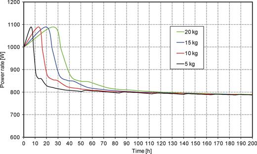
Effect of the filling amount on the dynamic response of the systems (TSOIL= 12°C, TAIR= 28°C, LGHE= 95 m).
5 CONCLUSIONS
This paper presents a preliminary study on the technical feasibility of an anti-gravity PTPT for semi-passive ground source cooling applications in the summer by transferring heat directly from the room air to the ground. This device may easily be applied to the server room or other small envelopes, and it may also be combined with natural ventilation or evaporative cooling for air pre-cooling. The PTPT can operate with the condenser placed from 1 up to 11 m below the evaporator. An approximate analytical model based on a lumped capacitance method has been developed. This model has been used to simulate the long-term performance of the PTPT device to evaluate the influence of the main operating parameters on the cooling rate. Ammonia has been chosen as the working fluid in the simulation. The numerical simulation has shown that a prototype design of the PTPT device is able to achieve a cooling rate from a minimum of 200 up to1000 W for the room temperature of 25–32°C. The cooling rate of 200 W may be obtained for the ground temperature of 20°C when the condenser is placed at the ground depth of 1 m. At higher depth with a ground temperature of 12°C, the cooling rate increases up to 1000 W. Due to the poor heat transfer performance of soil, a length of >50 m would be required for the ground condenser coil to achieve a considerable cooling rate.
ACKNOWLEDGEMENTS
Thanks to SOCRATES staff exchange programme for a grant to help the interactions between the authors.
