


Summary
Based on experimental observations and theoretical analyses, the author introduces an ideal microcrack model in which an array of cracks with the same shape and initial size is distributed evenly in rocks. The mechanism of creep dilatancy for rocks is analysed theoretically. Initiation, propagation and linkage of pre-existing microcracks during creep are well described. Also, the relationship between the velocity of microcrack growth and the duration of the creep process is derived numerically. The relationship agrees well with the character of typical experimental creep curves, and includes three stages of creep. Then the damage constitutive equations and damage evolution equations, which describe the dilatant behaviour of rocks, are presented. Because the dilatant estimated value is taken as the damage variable, the relationship between the microscopic model and the macroscopic constitutive equations is established. In this way the mechanical behaviour of rocks can be predicted.
1 Introduction
Dilatancy of rocks plays an important role for tectonic movements inside the Earth as well as in many aspects of engineering (Brace 1966; Brace 1978; Tan Tjong Kie & Kang Wen-fa 1983). Many laboratory studies have been stimulated by the hypothesis that dilatancy is believed to play an important role in the mechanism of shallow earthquakes (Nur 1972; Scholz 1973). Basic studies on dilatancy are very helpful in gaining a better understanding of the complexity of fracturing in rock mechanics. The formation of cracks and loosening substances around a tunnel, which may lead to gradual instability, is also attributed to dilatancy.
To obtain a better understanding of the tectonics of the crust and the genesis of earthquakes, a profound knowledge concerning the brittle behaviour of rocks at various stresses and temperatures is desirable (Tan Tjong Kie 1989; Ngwenya 2001). A basic property of the rheology of rock is creep deformation. Under normal stresses, the typical creep curve may be subdivided into three parts: (1) transient creep in which the strain rate decreases with time; (2) steady creep in which the strain rate is constant; and (3) tertiary creep in which the strain rate increases progressively until failure. However, the microscopic mechanism of creep in rocks has not been studied comprehensively.
At low temperatures, it is observed that the volume strain of rocks under pressure increases with time due to the extension of microcracks in rocks (Kranz 1979). During experiments, it is also found that a crack often shows a significant extension rate at a value of stress intensity factor lower than the critical stress intensity factor Kc. Such a phenomenon may be attributed to several mechanisms including a dependence upon the chemical environment, among which stress corrosion is mentioned most frequently (Martin 1972; Anderson & Grew 1976; Atkinson 1984; Atkinson & Meredith 1987). Stress corrosion involves the weakening of strained bonds at crack tips with the chemical action of, for example, water, thereby facilitating crack growth. Other contributing mechanisms include dissolution, diffusion, ion exchange and microplasticity.
The concept of different scale media may be used to explain that a rock can exhibit different mechanical properties. For example, brittle rocks exhibit a creep-dilating behaviour under triaxial stresses, but when rock material around microcracks is viscoelastic there is no swelling. Such dilatancy is the result of an extension of microcracks, namely when dissipation of energy leads to subcritical growth of cracks over time. Therefore, the rock specimen as a whole has the properties of both viscoplasticity and time-dependent dilatancy, while the skeleton of the rock is viscoelastic.
In this paper, rheological fracture mechanics is used to analyse the process of crack growth for rocks during creep to explain the mechanism of creep dilatancy for rocks. A differential equation that describes the relationship between the deformation velocity of the rock and time is obtained. By solving this equation, a relationship between volumetric swelling and time is derived. It agrees well with the character of typical experimental creep curves.
Moreover, equations for damage constitution and damage evolution are presented. In these equations, the dilatancy volume strain is taken as the damage variable. The damage evolution equation can be determined from the creep curves obtained via an analysis of the course of microcrack extension. By this procedure we intend to find a way to establish and describe the macroscopic mechanical behaviour of rocks through an analysis of their microscopic structure.
2 Model of Microcracks
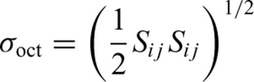
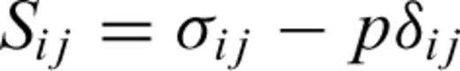
Most rocks contain inhomogeneities such as small cavities or cracks, particles with poor cohesion, as well as phases with different modulus or strengths from those of the matrix. Generally, the distribution of microcracks in rocks is very complicated. Therefore, it is very difficult to analyse the growth of various cracks in a complete way. However, based on experiments (Topponnier & Brace 1976; Waza 1980; Wong 2001), the sharp inclined crack shown in Fig. 1 is a model of a typical microcrack in rocks; two wings of the crack lie parallel to the maximum principal compressive stress. As for the mechanism of inelastic dilatancy in rocks, most studies focus on the sliding crack model first proposed by Brace (1966). The theoretical analysis by Nemat-Nasser & Horii (1982) and the numerical simulation by Tang & Kou (1998) show that under triaxal compressive stresses, the inclined crack in solids will extend in the direction at an angle of 0.39π from the crack inclination, and continue to extend parallel to the maximum compressive stress direction σ1.
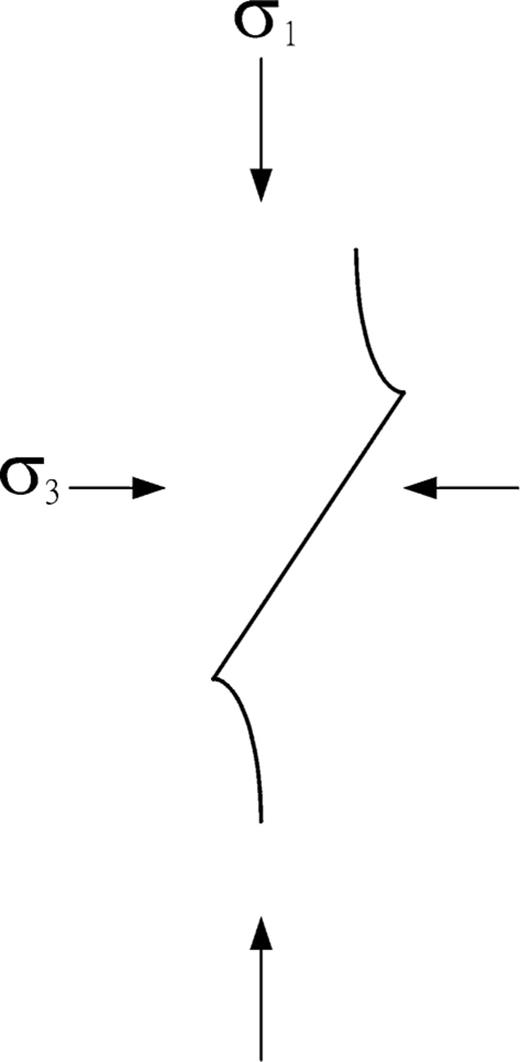
A wing crack.
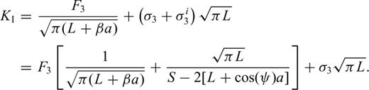
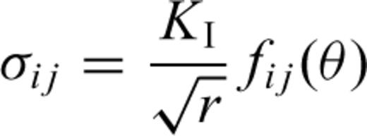
Based on experimental observations and a theoretical analysis, the author introduces an ideal model for microcracks, which is quite similar to the model proposed by Ashby & Sammis (1990). In this model, an array of cracks with the same shape and initial size are distributed evenly in rocks (Fig. 2). Under triaxial compressive stresses, the crack will extend parallel to the direction of the maximum compressive stress. In accordance with Ashby & Sammis (1990), the stress intensity factor at tips of a wing crack is analysed as follows.
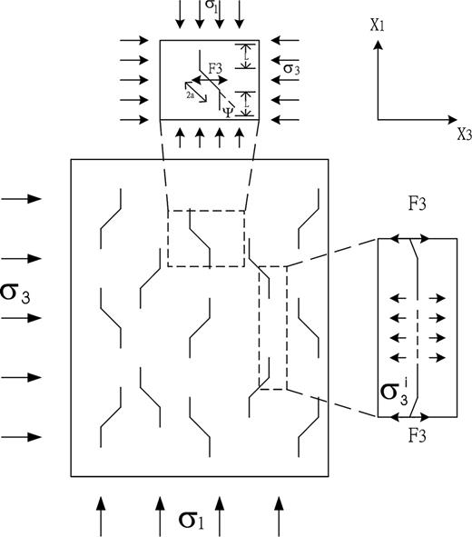
Model of extending microcracks.

It creates a stress intensity factor tending to open the crack (Tada 1985).
3 Analysis of Microcrack Extension for Creep Dilatancy
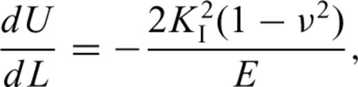
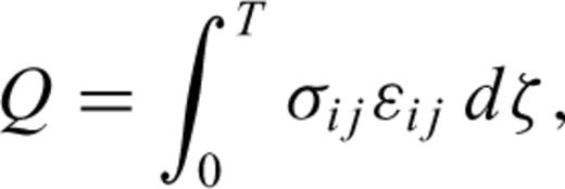
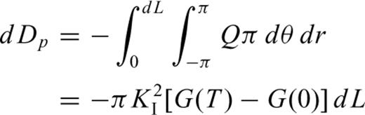
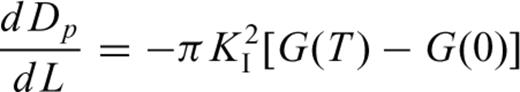
Griffith (1924) has indicated that if a crack grows to length L, the release rate of elastic energy is greater than or equal to the increasing rate of surface energy, so the crack will be in an unstable state and must extend. If we suppose that the medium around the crack is viscoelastic, due to the stress singularity at the tips of cracks, a higher dissipation of energy will occur, which will cause a subcritical extension of microcracks. In this paper the law of conservation is applied directly as the failure criterion. This method is a generalization of the classical Griffith approach for cracks in elastic materials.
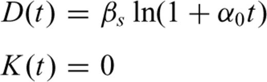
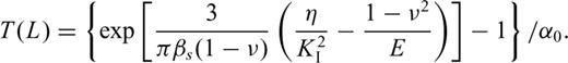
To make the analysis easier, we suppose the extension of cracks will take place step by step. Accordingly, when the stresses act on rocks for the time period T(L= 0), the crack begins growing to a length L and then stops. At another time period T(L) later on, the crack continues to grow to a new length L and stops again. Furthermore, there exists a critical length Lc. When L is larger then Lc, T(L) is equal to zero, which means crack growth will accelerate until failure. T(L) is the time period from the stop of the last crack extension up to the start of the next crack extension.
4 Computing Analysis
Solving the differential eq. (19) using the Runge–Kutta algorithm, the relation between the length L and time t, and the relation between the creep volume strain and time may be obtained. Plausible values of parameters required for computational purposes are taken as a particular example. Fig. 3 displays a theoretical curve that is in line with a typical creep curve. The curve also includes three stages: primary, secondary and tertiary creep. Referring to eq. (5), it is obvious that in the primary creep stage, the stress intensity factor at the tips of cracks decreases with time due to the confining pressure; in the secondary creep stage, the stress intensity factor at the tips of cracks remains approximately constant with time due to the interaction of cracks and the confining pressure; while in the tertiary creep stage, the stress intensity factor at the tips of cracks increases quickly due to the interaction of cracks. These results show that the model established in this paper is an effective approach to describing the mechanism of creep dilatancy in rocks.
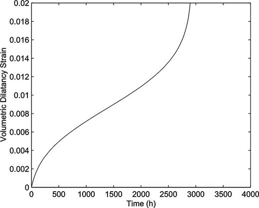
Creep volumetric strain curve computed by the model. The parameters for the computation are as follows: σ1= 120 MPa, σ3= 35 MPa, a= 0.2 cm, μ= 0.1, E= 50 000 MPa, ν= 0.25, β= 0.1, η= 1000 MPa, a0= 0.05/h, βs= 1 (MPa)−1, N= 3.3, αc= 0.05 cm, ψ= 45°.
The influences upon the crack extension velocity of the initial length of a crack, the inclination of a crack and the field stresses, are as follows.
4.1 Initial length of crack
Apparently, the crack extension velocity increases with the initial length of a crack. Fig. 4 shows a group of curves obtained with initial lengths of cracks ranging from 0.23 to 0.26 cm. Other parameters were unchanged (same as in Fig. 3). Fig. 4 reveals that the time of failure for rocks with shorter cracks is longer than that for rocks with longer cracks. The strain rate increases with increasing initial length of pre-existing cracks.
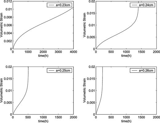
Creep volumetric strain curves computed for different lengths of crack.
4.2 Inclination of crack
Fig. 5 shows a group of curves obtained with crack inclinations changing from π/3 to π/5 but with other parameters as in Fig. 3 during creep. Obviously, the strain rate increases when the inclination of cracks changes from π/3 to π/4, while it decreases when the inclination of cracks changes from π/4 to π/5. So, it is interesting that the extending velocity of cracks does not depend monotonically on the inclination of cracks. This also means that the flat or steep inclination of cracks will exhibit a longer failure time, or say the cracks will extend with more difficulty.
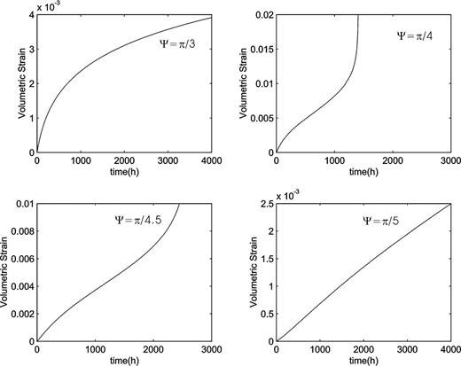
Creep volumetric strain curves computed for different inclinations of crack.
4.3 Confining field stress
The influence of confining field stresses upon the extension velocity of cracks falls in line with the theory and results we have expected. With increasing confining pressure the crack will extend with more difficulty and will require a longer failure time. This is shown in Fig. 6.

Creep volumetric strain curves computed for different confining pressures.
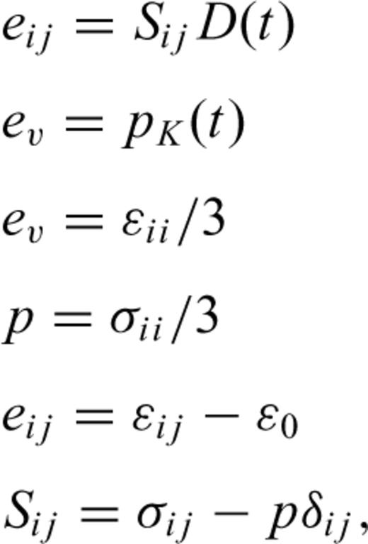
5 Constitutive Equation and Damage Evolution Equation
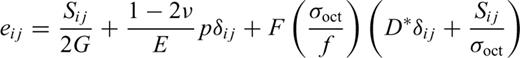
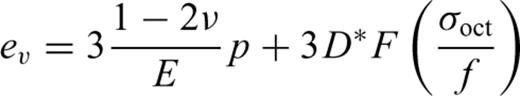

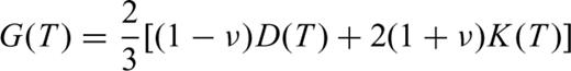
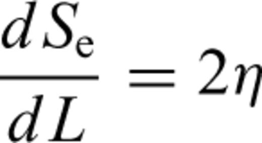
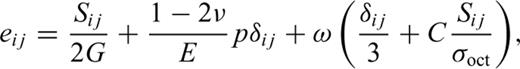
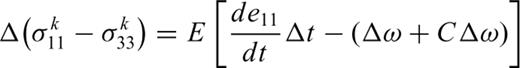
Eqs (21) and (22) include two parts: elasticity and plasticity. The first two terms in eq. (21) and the first term in eq. (22) represent the elastic strain characterized by the elastic parameters E, G and ν; the last terms in eqs (21) and (22) show the dilatant part. The parameter D characterizes the rock behaviour in the dilatancy regime and is called the dilatancy parameter. It can be seen from the above expressions that the dilatant strain is limited by the factor (σoct/f) and by the function F(σoct/f).


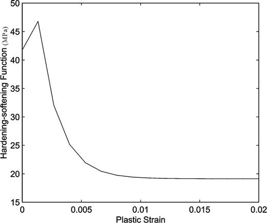
Hardening–softening H(ω) for the same parameters as Fig. 3.
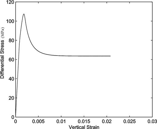
The predicated behaviour of stress–strain under a constant strain rate of 2 × 10⁻⁴ s−1.
6 Conclusion
An approximate physical model for time-dependent microcrack evolution in rocks under triaxial compressive stresses has been developed and analysed. The model is based on the subcritical growth of an array of small and inclined wing cracks as well as their interactions. The mechanism of creep dilatancy in rocks is well described through this model. The general agreement of the computational results with the typical creep curve for rocks indicates that this model is plausible. The analysis further indicates that the concentration of stresses at tips of microcracks, interaction of microcracks and energy dissipation are three important factors for crack extension in creeping rocks. The iterative analysis method for crack extension constitutes a distinguishing feature of this paper.
However, our final objective is to derive a macroscopic model for the mechanical behaviour of rocks through the analysis of microscopic structures. The work in this paper is only an initial attempt in this respect. It is concluded that the description of the mechanical property of rocks using the damaging mechanical method is a possible way of establishing a bridge between the macroscopic behaviour and the microscopic structure.
Acknowledgments
We thank Professors Bai Wuming and Yang Wenxiang for their careful reviews and constructive suggestions with regard to this paper. Thanks should also be given to the National Foundation Committee for Natural Science of China, which funded this study. The project code is 10032040.
References
