-
PDF
- Split View
-
Views
-
Cite
Cite
Hiroyuki Fujiwara, The fast multipole method for solving integral equations of three-dimensional topography and basin problems, Geophysical Journal International, Volume 140, Issue 1, January 2000, Pages 198–210, https://doi.org/10.1046/j.1365-246x.2000.00016.x
Close - Share Icon Share
Summary
The fast multipole method is developed for the solution of the boundary integral equations arising in wave scattering problems involving 3-D topography and 3-D basin problems. When coupled with an iterative solver for linear equations, the fast multipole method can significantly reduce memory requirements. The order of operations for the product of the matrix obtained from the discretization of the integral kernel and a vector is reduced from N2 to the order of pαN, where p is the order of the multipole expansion and α depends on the details of the implementation. In order to achieve efficient implementation the translation operators for the multipole expansion need to be used in the diagonal form based on a spherical wave decomposition.
For problems with topography, the number of iterations required of the linear equation solver to achieve convergence is small and no preconditioning is necessary. However, for a basin problem, block-diagonal preconditioning is essential in the application of the iterative solver. Both the memory requirements and the CPU time are considerably reduced for topography problems. Although the memory requirement is reduced for a basin problem used in this numerical experiment, the CPU time would be still longer than that for the ordinary boundary element method if sufficient memory were available. These results indicate that the fast multipole method might be much more efficient than the ordinary method for 3-D elastic wave scattering problems with more than several tens of thousands of unknown variables.
1 Introduction
During the last two decades there have been significant research efforts into boundary integral equation methods for solving problems of propagation of elastic waves. The recent advances of computer technology have allowed the solution of not only 2-D problems but also 3-D problems. Most of the basic difficulties in the formulation of various problems have been settled; if the size of the problem is within the capacity of a computer, many kinds of problems such as the effect of topography, basins, layered structures, inclusions and cracks can be solved. Because of the reduction in the number of dimensions used in discretization, boundary integral equation .015w>methods are powerful tools if the medium configuration is simple and the number of unknown variables is not too large. Many physical insights can be derived from the boundary integral formulations; for example, the transmission and reflection matrices defined for 1-D structures can be generalized to 2-D and 3-D structures by using boundary integral formulations (Hatayama & Fujiwara 1998).
However the technique has limitations related to the size of the matrix obtained by discretization of the boundary integral equation. Since the kernel function of the boundary integral equation is not a rapidly decreasing function in the frequency domain, the matrix is full and often non-symmetric. For a problem with N unknown variables, a linear equation system represented by an N×N full matrix has to be solved. If we use the LU decomposition method, the order of computation is N3. Even for an iterative method such as the biconjugate gradient method, the order of the computation is MN2, where M is the number of iterations. The restriction of memory size to store the N×N full matrix often prohibits us from computing such large problems.
To overcome the disadvantages of the boundary methods, Bouchon (1995) have proposed a method for a 2-D layered medium, in which the full matrix is approximated by a sparse matrix by assuming that matrix elements of small absolute value can be replaced by zero. Ortiz-Alemán (1998) have developed this method for 3-D topography. The disadvantages of the boundary methods have also been widely recognized in other research areas such as electrodynamics, aerodynamics and applied mathematics. A number of fast solution methods for integral equations have been undergoing intensive development during the last 10 years. Successful candidates for such fast solution methods are the fast multipole method (Greengard 1988), the panel-clustering method (Hackbusch & Nowak 1989) and the wavelet method (von Petersdorff & Schwab 1997). These methods are combined with an iterative method for solving linear systems with the aim of reducing both the computation and the memory requirements of the product of a matrix and a vector from N2 to the order of NlogαN (α≥ 0).
The purpose of this paper is to investigate the application of the fast multipole method (FMM) to the solution of integral equations of 3-D elastic waves. The FMM was originally proposed by Rokhlin (1985) and was developed by Greengard (1988) for the computation of potential fields. Rokhlin (1990) has extended the FMM to solve 2-D acoustic wave scattering problems and Coifman (1993) have solved 3-D electromagnetic scattering problems. Fujiwara (1998) has investigated the application of the FMM to the 2-D seismic scattering problems and has concluded that the combination of the FMM and iterative methods can reduce the computation and memory requirements by 1 or 2 orders of magnitude for problems with more than 10 000 unknown variables, if the problems can be described by Fredholm integral equations of the second kind.
Here, the fast multipole method is introduced for a problem with 3-D topography; we then investigate the order of the expansion that is required to achieve the desired accuracy. Applying the FMM to 3-D topography and basin problems, we study the convergence properties of the iterative method and discuss ways to produce efficient preconditioning.
2 The fast multipole method
The FMM was originally proposed for simulations of potential fields involving a large number of particles. Later it was recognized that the FMM can be adapted to the solution of boundary integral equations. The FMM can be regarded as an efficient algorithm to compute the product of the matrix and the vector that are obtained from discretization of an integral equation. The ordinary method requires N2 operations to compute the product of an N×N matrix and a vector. In the FMM algorithm the order of operations can be reduced to N. The basic idea for the reduction of computations for multiplication of a matrix and a vector is as follows. Let us consider multiplication of a matrix and a vector, y=Ax. If we have no information on A, we have to calculate

This calculation requires O(N2) operations. If aij can be written as

then we can take the common factor q1x1+˙˙˙+qnxn and reduce operations to O(N),

In the FMM algorithm we construct hierarchical common factors or ‘hubs’. Schematic representations of matrix vector multiplications are shown in Fig. 1. Fig. 1(a) is an ordinary method and (b) shows the FMM algorithm. To calculate the ‘hubs’ in the FMM, we need the multipole expansion of Green’s functions and translation theorems for the multipole fields. In the following, we will develop the algorithm for the FMM for 3-D elastic problems.
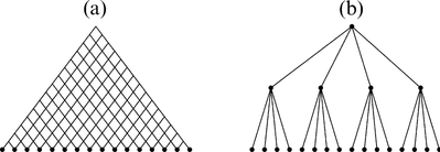
Schematic representation of matrix vector multiplication. The ordinary method (a) requires N2 computations. If we use the hierarchical ‘hubs’ shown in (b), we can reduce the number of computations.
We will apply the FMM to a 3-D topography problem using the direct boundary element formulation in the frequency domain. We use a Cartesian coordinate system and assume a time dependence of eiωt. The basic equation of the direct boundary method is the representation theorem (e.g. Aki & Richards 1980), and the 3-D topography problem can be written as

where uk(y) is the displacement, uINk(y) is the incident displacement and S is the free surface. The subscripts stand for the Cartesian components. The integral must be evaluated by means of the Cauchy principal value. Using the Green’s function, that is, the displacement in the j-direction at x for a unit force acting in the k-direction at y,

the kernel function of the integral equation Hj > k(x ; y) is given by


where Gjk, i is the derivative of Gjk with respect to the i-direction and ni(x) is the ith component of the unit normal vector pointing outwards at x, kα and kβ are the wavenumbers for P and S waves, respectively, λ and μ are the Lamé constants and r=|x−y|.
Eq. (4) contains an integral over an unbounded surface S. However, since the unbounded surface cannot be discretized, we use a modified equation that contains integrals over bounded surfaces; this modification is called the reference solution approximation (Fujiwara 1996). The modified equation is given by

where uHk(y) is the reference solution for the half space, S0 is the free surface used for the discretization and SI is the flat surface of the half space that corresponds to S0 and

Eq. (8) can be written in an operator form as

In this article, we use triangular constant elements to discretize eq. (10) and we use the same notation for the discretized matrix equation. The matrix H00 is full and non-symmetric. One of the methods to solve this linear equation is the LU decomposition method, which is numerically stable. However, LU decomposition requires computations of the order of N3 and a core memory of the order of N2. For 3-D problems, N can easily reach several thousand. The LU decomposition method is not effective for such large N. Instead of direct methods such as the LU decomposition method, iterative methods have been employed for solving such large matrices. If we combine an ordinary BEM with an iterative method—the biconjugate gradient method, for example, which is an extension of the conjugate gradient method to non-symmetric systems—MN2 operations are needed, where M is the number of iterations. When the condition number of the matrix is small and the convergence is fast, this method can be faster than the direct methods. However, the memory requirements are the same as for the direct methods. The restriction of memory size often prohibits us from computing large problems. For example, 1 GByte of memory permits values of only up to about N=8000 if we use double precision. This means that the maximum number of elements for 3-D topography problems is about 2670 for 1 GByte of memory.
The combination of the FMM and an iterative method for non-symmetric linear systems is one of the candidates for a fast solution method for large-sized problems. The FMM can reduce the computations of the product of a matrix and a vector from N2 operations to the order of pαN, where α depends on an implementation, by using a pth order multipole expansion of the Green’s function.
Before describing the algorithm, we prepare the mathematical tools needed for the fast multipole method. Since the basic function in the Green’s function for 3-D elastic problems is e−ikr/r, where r=|x−y|, we first consider the multipole expansion of the function e−ikr/r. Mathematical details are given by Epton & Dembart (1995). Using the spherical coordinates whose origin is not located at x or y, e−ikr/r can be written in a form of series expansion,

where Ymn are the spherical harmonics given by

where Pmn is the associated Legendre function of degree n and order m, and jn and h(2)n are the spherical Bessel function and the spherical Hankel function, respectively. The functions Omn and Imn are given by


The expansion is regarded as the representation of the Green’s function using the system of eigenfunctions for the spherical coordinates. It should be noted that the variables x and y are separated. The expansion is called the multipole expansion with respect to x and the local expansion with respect to y.
The full-space Green’s function for 3-D elastic problems can be written by using the multipole expansion as

In the algorithm of the FMM, the multipole representations need to be translated in space in order to calculate the hierarchical ‘hubs’. The following addition theorems are candidates for constructing multipole translation operators that shift the origin of the expansions:

where


in terms of a Wigner 3-j symbol (e.g. Messiah 1968)

and

The above addition theorems are referred to as the convolutional form since the corresponding translation operators are represented by a p2×p2 full matrix. If we use these translation operators, p4 computations are needed for one operation. Therefore, the algorithm based on these operators is not efficient for practical N < 105.
To overcome this difficulty, using the analogy of the Fourier transform in which a convolutional form is transformed into a product form, we employ the following transformation:

where S2 is the surface of the unit sphere and dωs=sinθdθdφ. The transformation can be regarded as a spherical wave decomposition. The multipole expansion of the Green’s function in the transformed domain is given by

where

and


where Pn is the Legendre polynomial of degree n.
In this domain, the spatial differentiations in eq. (16) that need complicated calculation are replaced by only the products of si. It should be noted that the operator MK can be defined only by using approximations, since the series is divergent, although the product of MK and I^φθ is convergent. The series in MK must be approximated by a finite series. From the numerical point of the view, some care is required for the choice of K in eq. (27) to avoid unacceptable errors caused by round-off.
The addition theorems in the transformed domain are given by the following simple forms:


The above addition theorems are called the diagonal form, since the translation operators constructed from these addition theorems are represented by diagonal matrices with dimen-sion p2. One operation of these translation operators requires only p2 computations.
The integral in eq. (22) can be estimated numerically by the following procedure. We employ the Gaussian quadrature formula

where wpr are coefficients of the Gaussian quadrature rule with p points and


With this approach, 2 p4 computations are needed for one integration. A fast algorithm to reduce this computation to the order of p3, which uses a fast algorithm for the Legendre transformation, was proposed by Alpert & Rokhlin (1991). This may be efficient for a problem with large p.
Using the addition theorems in the diagonal form, we can define the diagonal translation operators:


and


where I^ij(k, x) and O^ij(k, x) are the coefficient vectors of the multipole expansion and local expansion of the Green’s function, respectively. Explicit expressions for TP, SMM, TP, SML, TP, SLL, I^ij(k, x) and O^ij(k, x) are given in Appendix A. The linear operators TPMM and TSMM are the translation operators for the coefficients of the multipole expansion for the P-wave and S-wave terms, respectively, and are used to shift the centre of the multipole expansion. TP, SML is the operator for conversion from a multipole expansion to a local expansion, and TP, SLL is the translation operator to shift the centre of the local expansion.
In the FMM, we have to divide the whole domain to define hierarchical subdomains imposed on a tree structure and calculate a numerical ‘hub’ for each subdomain. We consider a rectangular solid domain V(0) that includes the whole discretized surface of the topography problem. The hierarchy of subdomains is defined as follows (Fig. 2). The subdomain of level 0 is equivalent to the entire domain V(0). The subdomain of level l+ 1 is obtained from that of level l by subdivision of each subdomain into four or eight equal parts, depending on the level of the subdomain and the ratio of the vertical size to the horizontal size of V(l)i. A tree structure is imposed on this hierarchy of subdomains, so that if subdomain V(l)i is fixed at level l, four or eight subdomains V(l+ 1)ij at level l+ 1 obtained by subdivision of V(l)i are regarded as its children.
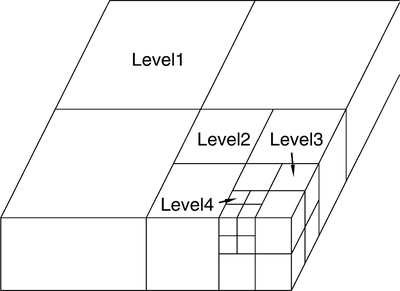
The hierarchy of subdomains for the FMM. A tree structure is imposed on the hierarchy of subdomains. A subdomain defined at level l is divided into four or eight subdomains at level l+ 1.
In the FMM algorithm, the interactions between nearby elements, that is, those with the nearest and the second-nearest neighbours at the finest mesh level, are calculated by the ordinary method, and other interactions are calculated by using the fast multipole technique (Fig. 3).
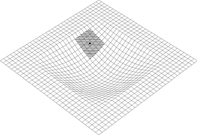
Interactions between elements that are included in the nearest and the second-nearest neighbours at the finest level of subdomains, denoted by the shaded zone, are calculated using the ordinary method. Other interactions are calculated using the FMM.
The details of the algorithm used here, based on the original version of Greengard (1988), are summarized as follows (Fig 4
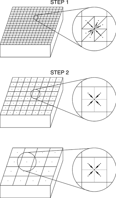
Schematic representation of the algorithm for the upward pass of the FMM. In the upward pass, the coefficients of the multipole expansions about the centres of all subdomains are calculated at all levels to construct hierarchical ‘hubs’.
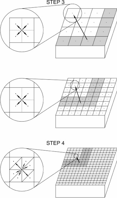
Schematic representation of the algorithm for the downward pass of the FMM. In the downward pass, contributions from elements located in the far field are summed using the hierarchical ‘hubs’.
2.1 Step 1
Form the coefficients of the multipole expansions Φ^Pk(L, m) and Φ^Sk(L, m) of the contributions from the elements included in each subdomain S(L)m about the centre of the subdomains at the finest mesh level L. For our model, this means that we calculate the coefficients of the multipole expansion for each element at the level L mesh and sum them up to obtain


where Nm is the number of elements included in the subdomain S(L)m and ΔSl is the size of the element.
2.2 Step 2
Form the coefficients of multipole expansions about the centres of all subdomains at all coarser mesh levels using the translation operator TP, SMM, which shifts the centre of the expansion to sum up the coefficients of the multipole expansions at finer mesh levels. For our model, calculate

for l=L to l=3, where K(l) is the number of children of subdomain V(l− 1)m.
2.3 Step 3
Form coefficients of the local expansion Ψ^P, Sk(l, m) about the centre of each subdomain V(l)m at each mesh level l using the translation operator TP, SML, which operates on the coefficients of the multipole expansion to convert them to the coefficients of the local expansion. This local expansion describes the contribution due to all elements in the domain that are not contained in the current subdomain, its nearest neighbours, or its second-nearest neighbours. Once the local expansion is obtained for a given subdomain, it is shifted by using the translation operator TP, SLL to form the initial expansion for the subdomains at the next level. For our model, calculate

and

for l=3 to l=L, where Nm is the number of subdomains included in the shaded zones in Fig. 3. The shaded zone at mesh level l is the set of subdomains V(l)m that are children of the nearest and the second-nearest neighbours of the parent V(l− 1)jm of V(l)m and that are not the nearest or second-nearest neighbours of V(l)m.
2.4 Step 4
Evaluate the local expansion at positions of elements to obtain all contributions from the elements in the far field and transform to the original space. For our model, calculate

and transform H^u to Hu. The definition of I(kα β, y) is given in Appendix A.
2.5 Step 5
Compute the interactions due to near neighbours directly by using the ordinary technique of the boundary element method. For the singular elements we analytically integrate the static part of the Green’s function, since the singularity of the static part is equal to the singularity of the Green’s function and the static part can be integrated analytically for triangular constant elements. Non-singular terms are integrated by using the Gauss quadrature formula. For the integration of the nearly singular elements we employ the PART (projection and angular and radial transformation) method (Hayami & Matsumoto 1994).
Next we consider the algorithmic complexity of the FMM. The complexity of the FMM is proportional to the number of the subdomains. Although the number of levels of the subdomain is proportional to logN, the number of subdomains included in level l is 1/4 or 1/8 times the number of subdomains of level l+ 1. If we assume that the number of subdomains of level l is 1/8 times that of level l+ 1 and that the number of boundary elements included in the finest subdomain is M, then the number of subdomains included in all levels is

Therefore, the complexity of the FMM is O(N).
3 The order of the expansion
We need to select p large enough that the multipole expansion of the Green’s function converges to the desired accuracy. From theoretical considerations (Rokhlin 1993), it is known that the required order of the multipole expansion for a given accuracy is proportional to k|x|. From the numerical point of view, this theoretical consideration is not sufficient and numerical experiments are required, because we have to estimate the total error, which includes not only the error of the expansion but also the error from all translation operations. As a function of n, the Bessel function jn(x) decays rapidly and the Hankel function h(2)n(x) grows rapidly for n > x, which causes numerical instabilities. In particular, the translation operator from the multipole expansion to the local expansion, MK, requires special attention in the numerical treatment. Although we need to select K as K≥ 2p to construct a mathematically complete MK, we must employ the restriction K≤p− 1 due to the limitation of the degree in the Gaussian quadrature (31). Even if we employ K≤p− 1, numerical instabilities often occur since the series in MK is numerically unstable. Although the product of MK and I^φθ must always have a finite value, the series in MK is divergent. Therefore, the round-off error in the product of MK and I^φθ often causes unacceptable numerical error.
We have carried out the following numerical experiments to investigate the numerical error in the FMM. We consider a curved surface on which point sources are distributed as shown in Fig. 6. The curved surface is specified by
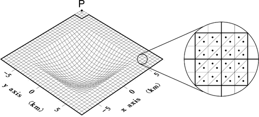
Configuration of the model to estimate the numerical error in the approximation of the FMM. The curved surface is divided into 8192 triangular elements and point sources are located at the centre of gravity of each element. We calculate the sum of all contributions from the point sources to the point P by using the FMM. The contributions from sources included in the nearest and second-nearest neighbours of the finest level are excluded.

for − 8 ≤x≤ 8 (km) and − 8 ≤y≤ 8 (km). The curved surface is divided into 8192 triangular elements and the point sources are located at the centre of gravity of each element. The P- and S-wave velocities of the medium are 4.8 and 2.8 km s− 1, respectively, and the density is 2.4 g cm− 3. The contribution from sources included in the nearest and second-nearest neighbours of the finest mesh level is excluded. We calculate ui and ti, which consist of contributions from all sources to the point P that is located at the corner of the surface; ui and ti are given by


We calculate ui and ti by the FMM and the BEM and estimate the numerical error in the FMM using the following measures:


where uFi, tFi and uBi, tBi are calculated by the FMM and the BEM, respectively.
Figs 7(a) and (b) show the results of the numerical experiments for E(u) and E(t), respectively. E(t) is about 10 times larger than E(u). Roughly speaking, the errors are proportional to the frequency. However, the error E(u) increases at low frequency for p=12; this is caused by a numerical instability in the calculation of MK, The results in Fig. 7 are obtained from the best selection of K for each level of translation MK to minimize the errors E(u) and E(t). Table 1 shows the selection of K for each level of translation MK; (a) is for E(u) and (b) is for E(t), From the theoretical considerations, K=11 would be the best selection for all levels of translation in the case of p=12. In the numerical simulation, however, K=6 is the best for the case of E(u) and f=0.1 Hz. It is difficult to provide a simple interpretation of the error. The selection of K will ultimately be settled by numerical experiment.
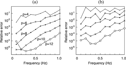
Relative errors caused by the truncation of the multipole expansion for (a) E(u) and (b) E(t).
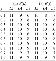
The selection of K for each level of translation MK that minimizes the errors E(u) and E(t) for p=12.
Fig. 8 shows the required order of the multipole expansion p to guarantee a given accuracy. The required values of p for E(u)=10− 2, 10− 3 and E(t)=10− 2, 10− 3 are shown. The order p is plotted as a function of kβL, where kβ is the wavenumber for the S wave and L is the spatial size of the problem. The order p is proportional to kβL.
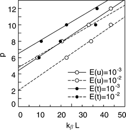
The required orders of the multipole expansion to guarantee given accuracies of 10− 2 and 10− 3 are shown for E(u) and E(t). The order p is plotted as a function of kβL, where kβ is the wavenumber for the S wave and L is the spatial size of the problem.
In the above experiments we have estimated the relative error in the FMM. The FMM is only applied to the calcu-lation of off-diagonal elements, which are much smaller than diagonal elements. The relative error in the FMM combined with the BEM is much smaller.
4 Convergence of iterative methods
To solve an integral equation by using the FMM, we have to combine the FMM with an iterative method for linear equations. Since the matrix in our method is non-symmetric, we need to use an iterative method for a non-symmetric matrix. Although non-symmetric matrices have some disadvantages in numerical computations, many methods have been developed recently. In this study we use the conjugate gradients squared (CGS) algorithm (Sonneveld 1989) as an iterative method. The CGS algorithm is a modification of the biconjugate gradients (Bi-CG) algorithm. The CGS does not involve adjoint matrix vector multiplication, which makes the implementation of the FMM easy, and the expected convergence rate is about twice that of the Bi-CG.
The number of iterations for the convergence depends on the condition number of the matrix. We study the convergence property of the CGS applying the FMM to 3-D topography and basin problems. For a problem of 3-D topography, the integral equation in operator form is given by

This is a Fredholm integral equation of the second kind.
On the other hand, for a 3-D basin problem, the integral equation in operator form is given by

This is a Fredholm integral equation of the second kind for ui( j) but the first kind for t2(1). The definitions of the matrices are given in Fujiwara (1996).
First we consider a 3-D topography problem. The configuration of the surface is the same as the model employed to investigate the accuracy of the FMM. The curved surface is defined by eq. (48). The surface is divided into 8192 triangular elements; the matrix size is then N=24 576. The incident wave is a plane S wave with an incidence angle of 0. The P- and S-wave velocities of the medium are 4.8 and 2.8 km s− 1, respectively, and the density is 2.4 g cm− 3. The linear equation is solved by using the CGS. The matrix H00 has a block-diagonal submatrix that consists of 3 × 3 matrices for singular elements. The block-diagonal matrix is used for the preconditioning. We compare the speed of the convergence for the CGS without preconditioning and the CGS with block-diagonal preconditioning. The results of the numerical experiments are shown in Table 2. The required numbers of iterations for the residuals to become smaller than 10− 2 and 10− 4 are shown for (a) non-preconditioning and (b) block-diagonal pre-conditioning. From this numerical experiment we can conclude that the preconditioning does not improve the convergence properties. Even if we do not use any preconditioning, the speed of the convergence is very fast, although the number of iterations increases as a function of the frequency. Observation points are located on the four solid lines shown in Fig. 9 for the waveforms calculated for the topography model, which are shown in Fig. 10.
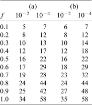
The required numbers of iterations for the residuals to become smaller than 10− 2 and 10− 4 are shown for (a) CGS without preconditioning and (b) CGS with block-diagonal preconditioning for the 3-D topography problem.
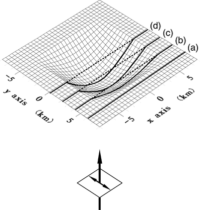
The locations of observation points for the topography and basin models. The solid lines show the observation points for the topography model and the dotted lines show the observation points for the basin model.
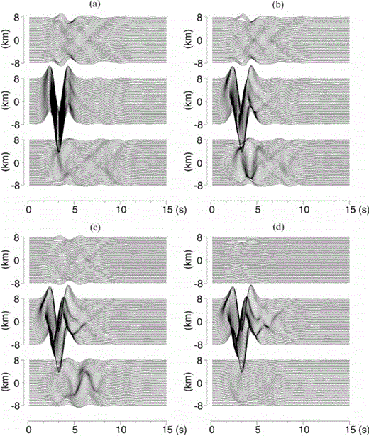
Waveforms calculated for the topography model. The locations of observation points are shown in Fig. 9. The x-, y- andz-components of waveforms are shown from top to bottom of each panel. The incident wave is a plane S wave with an incidence angle of 0and its shape is a Ricker wavelet of centre frequency 0.4 Hz. The P- and S-wave velocities are 4.8 and 2.8 km s− 1, respectively, and the density is 2.4 g cm− 3.
Next we consider a 3-D basin problem. The shape of the boundary surface between the basin and the basement is the same as the curved surface of the topography problem. The incident wave is a plane S wave with an incidence angle of 0. The P- and S-wave velocities and the density of the basement are 4.8 and 2.8 km s− 1 and 2.4 g cm− 3, respectively, and those of the basin are 2.3 and 1.5 km s− 1 and 2.1 g cm − 3. For the basin problem, the boundary surface is divided into 2048 triangular elements and the size of the whole matrix is N=11 940. We compare the required number of iterations to converge for the CGS without preconditioning and the CGS with a block-diagonal preconditioning. The block-diagonal matrix for the preconditioning is given by

where the matrices Hii( j)+ 1/2 I and Gii( j) are block-diagonal matrices that consist of 3 × 3 matrices for singular elements.
The required numbers of iterations so that the residuals become smaller than 10− 2 and 10− 4 are shown for (a) non-preconditioning and (b) block-diagonal preconditioning in Table 3. For the basin problem, the speed of the convergence is very slow if we do not employ any preconditioning. However, by using the block-diagonal preconditioning, we can reduce the number of iterations drastically. The block-diagonal preconditioning is essential for basin problems. Waveforms calculated for the basin model are shown in Fig. 11; observation points are located on the four dotted lines shown in Fig. 9.
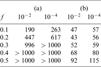
The required numbers of iterations for the residuals to become smaller than 10− 2 and 10− 4 are shown for (a) CGS without preconditioning and (b) CGS with block-diagonal preconditioning for the 3-D basin problem.
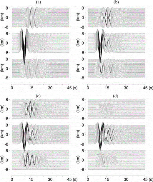
Waveforms calculated for the basin model. The locations of observation points are shown in Fig. 9. The x-, y- and z-components of waveforms are shown from top to bottom of each panel. The incident wave is a plane SH wave with an incidence angle of 0 and its shape is a Ricker wavelet of centre frequency 0.2 Hz. The P- and S-wave velocities of the basement are 4.8 and 2.8 km s− 1, respectively, and the density is 2.4 g cm− 3. The P- and S-wave velocities of the basin are 2.3 and 1.5 km s− 1, respectively, and the density is 2.1 g cm− 3.
Since the CPU time and memory requirements depend on the implementation of the algorithm and architecture of the computer, it is difficult to provide a good estimate objectively. The CPU times and memory requirements are measured in an implementation on a DEC alpha 600. For the 3-D topography problem with N=24 576 the memory requirement for the FMM is 459 MByte and the CPU time is 2660 s for 20 iterations for p=6. For p=8, the memory requirement is 625 MByte and the CPU time is 6040 s. This model cannot be calculated with the computer used in this experiment because of the memory limits, since the memory requirement for the ordinary method is 9.7 GByte. For a smaller-sized problem with N=6144 the CPU time of the ordinary method is 770 s. If we assume that the CPU time of the ordinary method is proportional to N2, the CPU time is 12 320 s for N=24 576. For the 3-D basin problem with N=11 940 the memory requirement in the FMM is 453 MByte and the CPU time for 20 iterations is 5220 s. Although this model also cannot be calculated on the computer, it is expected that the memory requirement is 2280 MByte and the CPU time is 2895 s from the theoretical consideration. It can be said that the memory requirement of the FMM is reduced by more than one order of magnitude and the CPU time is less than half of that of the ordinary method for 3-D topography problems with more than 20 000 unknown variables. Although the memory requirements can be reduced by the FMM for 3-D basin problems, the CPU time of the FMM is still longer than that of the ordinary method for the range N=10 000 ~ 20 000. The efficiency of the FMM depends on the order of expansion p, which is determined by the accuracy of the calculation. The order p required for a given accuracy depends on the problem and is proportional to kβL as discussed in the previous section. Therefore, it is difficult to find the minimum value of N at which the FMM becomes more efficient than the ordinary method of the BEM. In this article, using only two examples for numerical experiments, we investi-gate the efficiency of the FMM for 3-D elastic wave scattering problems. According to the numerical experiments, it is expected that the FMM becomes much more efficient than ordinary methods for problems with more than several tens of thousands of unknown variables.
5 Conclusions
In this paper the applicability of the FMM to integral equations for 3-D topography and basin problems has been investigated. The results are summarized as follows.
(1) We have to employ the diagonal forms of the translation operators for multipole expansions to reduce the number of computations. Although the convolutional form requires p4 computations for one operation, the diagonal form requires only p2 computations. The diagonal form can be obtained from the convolutional form by using the transformation of a spherical wave decomposition.
(2) The accuracy of the FMM depends on kβL, where kβ is the wavenumber of the S wave and L is the spatial size of a problem. The order of the expansion required to guarantee a given accuracy is proportional to kβL. The operator MK included in a diagonal translation operator involves a divergent series, which often causes numerical instabilities. Careful treatment of MK is necessary for numerical simulation.
(3) The FMM is combined with the CGS (an iterative solver for non-symmetric linear equations). Although for 3-D topography problems the number of iterations required to converge is small and no preconditioning is necessary, block-diagonal preconditioning must be used for 3-D basin problems.
(4) The memory requirement of the FMM is reduced by more than one order of magnitude and the CPU time is less than half of that of the ordinary method for 3-D topography problems with more than 20 000 unknown variables. Although the memory requirements can be reduced by the FMM for 3-D basin problems, the CPU time of the FMM is still longer than that of the ordinary method for the range N=10 000 ~ 20 000. In this article, using only two examples for numerical experiments, we have investigated the efficiency of the FMM for 3-D elastic wave scattering problems. According to the numerical experiments, it is expected that the FMM becomes much more efficient than ordinary methods for problems with more than several tens of thousands of unknown variables.
Acknowledgements
I would like to thank Brian L. N. Kennett for useful discussions and helpful comments. Ken Hatayama helped me to calculate the integrals on singular elements. Yuzo Sinozaki kindly advised me on the PART method for integrals on nearly singular elements. Comments by two anonymous reviewers were useful in improving the manuscript. Part of this work was undertaken when the author was a Visiting Fellow at the Research School of Earth Sciences, Australian National University. The position was supported by the overseas research program of the Science and Technology Agency of Japan.
References
1
8
Appendix
APPENDIX A: Definition of the diagonal translation operators
The diagonal translation operators are defined by

and I^ij(kα ,β, x), O^ij(kα, β, x) and I(k, y) are given by


