


Abstract
Manufacturers of pacemakers (PM) and of magnetic resonance imaging (MRI) devices state that MRI scanning of PM wearers is contraindicated. This paper tries to summarise which effects can interfere with PM, what can be hazardous, and how treatment of PM in MRI can be modified to guarantee compatibility.
All PM tested were from deceased patients. Reed contact thresholds and reactions were investigated in low magnetostatic fields and compared with those in strong magnetostatic fields. Influence of gradient fields on PM and heating due to radiofrequency (RF) pulses were estimated. Thirty Legal Medicine Departments were questioned whether deaths of PM patients during MRI are known.
Reed contacts are influenced above 0.7 mT. In MRI fields only 28% of the PM in magnet mode remained so in all orientations. Of synchronous PM, 76% remained synchronous in all orientations. Gradient fields can influence sensing but cannot stimulate. Power density and temperature rise produced by RF fall rapidly with distance. Our question revealed six deaths. All suffered from sick-sinus-syndrome and all were not PM dependent. In three cases ventricular fibrillation was proven as the cause of death.
Asynchronous pacing due to magnetostatic and gradient fields may be problematic in patients with spontaneous rhythm. To avoid them, PM triggered MRI scan restricted to refractory period is proposed. Neither inhibition of PM nor heating of the electrode poses real risks. So far, we have examined eight patients 12 times in MRI triggered mode without problems.
Introduction
Both manufacturers of pacemakers and of magnetic resonance imaging (MRI) devices expressly state that examination of pacemaker wearers with MRI scanning is contraindicated. This warning must be understood as a preventive measure. Neither want to take responsibility in cases of incompatibility that were predicted as early as 1983 by Pavlicek and co-workers [1] . They suggested inhibition and alteration of normal pacing parameters due to time-varying magnetic fields. Fetter and co-workers [2] investigated, in vivo, four pacemakers of one manufacturer. They found normal magnet operation in single and dual chamber pulse generators except in the VDD mode, in which initially VOO mode was caused by the magnetic field followed by heart stimulation with the RF pulse period. They concluded that “patients with single-chamber implantable pacemakers may undergo scanning with NMRs (at that time “nuclear magnetic resonance”), provided the patient is monitored during scanning and the risks of asynchronous pacing are taken into account”. Fontaine and co-workers [3] first demonstrated rapid ventricular pacing during RF pulsing in a patient with a dual chamber pacemaker, though it was programmed to VVI and with the output parameters below threshold. In 2000, Sommer and co-workers [4] examined 44 non-pacemaker-dependent patients 51 times in a 0.5 T MRI device without any impairment of pacing function. They concluded that “MR imaging at 0.5 T can be safely performed in carefully selected clinical circumstances when appropriate strategies (programming to an asynchronous mode, adequate monitoring techniques, limited RF exposure) are used”. The risk–benefit ratio should be individually evaluated with an understanding that the performance of an MRI imaging examination poses the potential for serious harm (heating of the lead tip, rapid cardiac pacing, or inhibition). While the true number of deaths of pacemaker patients undergoing MRI is unknown, several have been reported [5 – 9] .
Although Vahlhaus and co-workers postulate in a paper [10] that “the general policy of never exposing a patient with a pacemaker to MRI should be revised”, they proposed restriction of examinations to
non-pacemaker dependent patients and
MRI devices with a flux density of 0.5 T and lower.
There are several questions to be answered: what can be done with pacemaker dependent patients and with magnetic fields of above 0.5 T? Can current pacemakers be programmed to allow MRI to be safe? Do we have to wait until pacemakers are designed to be resistant to magnetic resonance imaging? Why should only pacemakers be modified and not also MRI devices? Is it possible to modify current MRI procedures so that most of today's pacemakers can safely be examined? If these were possible, the question in the title of this paper would be answered. There is already a patent application of an “MRI-compatible pacemaker with pulse carrying photonic catheter providing VOO functionality” [11] . Is fixed rate tolerable or is one problem (MRI incompatibility) replaced by another problem (fibrillation by asynchronous pacing)? If pacemakers should be made compatible with MRI examinations, it is necessary to describe which effects are potentially incompatible in today's pacemaker patients and how safety could be established.
Pacemaker behaviour in low magnetostatic fields
In all pacemakers a reed contact or an equivalent electronic circuit is incorporated that is activated by a test magnet to assess device functions, mainly the battery status. Thus, the battery status of a pacemaker can be determined by magnet application to the device; a “magnet rate” pacing output will appear specific for each device and battery state. We have investigated how and at which magnetostatic fields pacemakers will react.
The diverse reactions with a test magnet applied are listed in Table 1 together with their frequency for which a population of 703 pacemakers representing 249 different models from nine brands was investigated. All pacemakers were removed from deceased patients who died between June 2002 and March 2004 and were left in the state as they were in the patient. We found:
Reaction of 703 pacemakers with a test magnet applied
| Reaction | N = 703 (249 models) |
|---|---|
| 90 min −1 ≤ HR ≤ 100 min −1 | 26.6% |
| 75 min −1 ≤ HR ≤ 85 min −1 | 21.0% |
| Asynchronous, program HR | 31.6% |
| Synchronous | 20.2% |
| Vario threshold test | 0.6% |
| Sum | 100.0% |
| Reaction | N = 703 (249 models) |
|---|---|
| 90 min −1 ≤ HR ≤ 100 min −1 | 26.6% |
| 75 min −1 ≤ HR ≤ 85 min −1 | 21.0% |
| Asynchronous, program HR | 31.6% |
| Synchronous | 20.2% |
| Vario threshold test | 0.6% |
| Sum | 100.0% |
26.6% were switched to an asynchronous mode with high rates of between 90 and 100 min −1 (asynchronous means “insensitive to heart signals”).
21.0% had an elevated asynchronous, above normal programmed rate.
The largest proportion , namely 31.6% paced asynchronously with the normal programmed rate.
20.2% were not influenced by the magnetic field which means that they worked in a synchronous mode with programmed rate (synchronous means “sensitive to heart signals”) .
0.6% (four devices) performed a threshold test continuously with stepwise decreasing output voltage (called “VARIO test” by the manufacturer, formerly Siemens-Elema, now St. Jude Medical).
If this test function is not recognized before MRI and programmed off, it could be hazardous for its wearer. Under the influence of a test magnet, all generators functioned according to the manufacturer's specification. This investigation reveals that it is not easy to predict the behaviour in a magnetic environment. The devices (47.6% (26.6% + 21.0%)) paced at an elevated rate, 51.8% (31.6% + 20.2%) at their programmed rate if spontaneous activity is absent. Whether a strong magnetic field will open a reed contact that was closed in a low field, as was experienced by Luechinger and co-worker [14,,15] , can only be established under certain conditions namely:
if asynchronous elevated rates of ≥75 min −1 (together 47.6% in Table 1 ) fall to normal rate below or
if spontaneous rates are present and more than 20.2% (portion of synchronous pacemakers in Table 1 ) are inhibited.
Both would indicate a difference in behaviour in strong magnetic fields. If the programmed rate is higher than the spontaneous, as was programmed by Vahlhaus and colleagues in their study [10] , it is hardly possible to differentiate between closed or opened reed contacts.
Force on pacemaker leads in a 1.5 T field
It is often stated that one danger for pacemaker patients in MRI magnetic fields could be dislodgement of lead or generator. Luechinger and co-workers [16] tested 31 pulse generators and 13 ICDs in a 1.5 T MRI scanner. They found low magnetic force or torque in pulse generators released after 1995 and up to 3.6 N in older models. ICD proved, all except one model, to exert higher forces up to 5.9 N. They did not investigate forces exerted on leads.
A qualitative investigation just at the bore of a 1.5 T MRI unit, where attraction is highest, revealed that tips of 33 leads (five manufacturers, 20 models) showed no attraction at all, whereas connector pins were slightly attracted. This means that the fear for pacemaker lead dislodgements due to high magnetostatic fields is entirely unfounded as the exerted forces are by no means high enough to effect retraction.
Pacemaker behaviour in a 1.5 T magnetostatic field
One hundred and twenty-seven pacemakers with known low magnetostatic field behaviour were inserted into the field of a 1.5 T MRI scanner. With test magnet applied, 72 of them reacted asynchronously, 55 of them synchronously. All were tested in three orthogonal orientations. A generator with a 20 mV, 10 ms square wave test signal was switched on and off to test whether or not synchronous mode in the pacemakers under test was present. The pacemaker was connected to 500 Ω load with a continuously measuring beat-to-beat time counter in parallel. The results were as follows.
Asynchronous pacemakers ( N = 72)
27.8% remained asynchronous in all three orientations,
15.3% were synchronous in one orientation,
37.5% were synchronous in two orientations,
19.4% were synchronous in all orientations.
Synchronous pacemakers ( N = 55)
76.4% remained synchronous in all orientations,
12.7% were asynchronous in one orientation,
3.6% were asynchronous in two orientations,
7.3% paced asynchronously in all orientations.
Thus, 23.6% were forced into asynchrony in one or more orientations.
No pacemaker was permanently inhibited by the magnetostatic field of the MRI scanner.
Influence of gradient fields on the pacemaker system
One can calculate that if d B /d t is up to 20 T/s (limit set by a standard to avoid peripheral nerve stimulation), a voltage of up to 450 mV (zero-peak) is induced in a lead loop of 225 cm 2 , an area that is the worst-case scenario of a large person with a left sided implanted unipolar pacemaker system [17] .
Assuming a pacemaker input resistance of 10 kΩ (normally higher) and a lead impedance of 700 Ω, a current of 450 mV/10.7 kΩ = 42 μA is induced into the loop causing voltage division between the input resistance and lead resistance. Most of the voltage, namely 10 kΩ × 42 μA = 420 mV (zero-peak) falls along the input resistance, whereas a voltage across the lead of only 700 Ω × 42 μA = 29.4 mV (zero-peak) is induced which is far below rheobase, so that even pacing of pulse trains is impossible. With higher input resistances, as are typical for modern pacemakers, the lead voltage further decreases.
The voltage of 420 mV (zero-peak) corresponding to 840 mV (peak-to-peak) is, however, strong enough to influence the sensing circuit. There are two possibilities that the sensing circuit of a pacemaker reacts: either by switching to interference mode or by inhibition of the atrial and ventricular channel.
and simultaneously
Inequality (3) is unlikely to occur as both conditions are not typical for MRI scanning. However, the start of every scan sequence can inhibit the pacemaker as all today's pacemakers perceive the onset of any signal above threshold as a heart signal and, if persisting, decide whether heart or interference signals are present [17] . This means that prolongations between paced heart beats are occasionally possible which are generally regarded as tolerable. Therefore, prolonged inhibition due to gradient fields seems to us to be unlikely to occur in MRI examinations.
Fig. 1 shows a diagram of the induced voltage due to a gradient pulse as it is seen by a pacemaker. The sinusoidal voltage induced by the gradient field in vertical orientation was measured with the aid of an artificial pacemaker patient model with 225 cm 2 area described elsewhere [17] . Though the sinusoidal signal with 0.6 ms duration is sharper than a heart signal, the amplitude of 180 mV is so large that it will surely influence the sensing circuit.
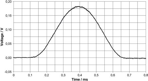
Oscillogram of the voltage induced into a pacemaker patient model with 225 cm 2 area by a vertical gradient field (40 kHz low pass filtering). d B /d t in this case is approximately 8 V/s.
The voltage in Fig. 1 is smaller than calculated above, the d B /d t value is approximately 8 V/s. Today's fast switching MRI machines may have a 10-fold higher d B /d t but with shorter pulse durations. The temporal course of the gradient pulses, not shown in Fig. 1 , resulted in switching to interference mode in this scan sequence, if the pacemaker worked in the synchronous mode.
Heating due to RF pulses
There are in vitro [4,,19] and in vivo [19] investigations that prove a heating effect at the lead tip due to the radio frequency (RF) pulses emitted during MRI scans. The induced voltages create electric fields around the electrode tip that are similar to that of pacing pulses. The calculation following assumes the electrode to be smooth and hemispherical. Another geometry can be approximated by using the surface area and calculating the radius of a corresponding hemispherical electrode. The surface structure, whether smooth or rough, plays practically no role with respect to the field produced by the electrode. This assumption has proved to be a good approximation in threshold calculations [20] .
where ro is radius of the electrode and Eo is the field at the surface of the electrode = voltage U divided by ro .
If the ratio R of the power density in a distance r related to that at the surface ro of the electrode is formed, the result is:
Inserting 2 ro for r into Eq. (7) yields a ratio of 1/16 or, in other words, in a distance which is equal to the radius of the electrode, the power density and with it the temperature rise produced has fallen to 1/16 of that at the surface. For example: a radius of 1 mm corresponding to a surface of a semi ball shaped electrode of 6.3 mm 2 produces a temperature rise 1 mm away from the surface which is 1/16 that at the surface. Normally, the layer of unexcitable tissue between the surface of the electrode and excitable tissue in the chronic state is said to be more than 1 mm [20] , so that heating takes place in a region around the electrode where tissue is not excitable and, therefore, will not influence threshold. Let us assume in the above example that a temperature rise of 5 °C at 1 mm distance is tolerable and reversible, then, 16 times 5 °C, or 80 °C, can be the temperature rise at the electrode surface which is four times higher than what has been measured in in vivo experiments [19] . Though the power density is only one determinant of thermodynamic equilibrium, its sharp decrease may be an explanation of why Luechinger and co-workers did not find histological damage in their experiments with up to 20 °C electrode temperature rise [19] .
Battery status and MRI examination
Vahlhaus et al. found a significant decrease in battery voltage after MRI examination from 2.763 V to 2.758 V ( P = 0.047) and concluded that “the battery voltage drop probably reflects only the continued operation of the pacemaker in the asynchronous mode for 99.5 min duration of the MRI examination” [10] . Our investigation should confirm what they deemed a probability. Six pacemakers from one manufacturer (St. Jude Medical) were investigated outside MRI as to whether increased current drain during a 1 h examination could alter the battery status due to increased rate (85 min −1 ), amplitude (4.5 V), and pulse duration (1 ms). Table 2 shows the results. The programmed output parameters remarkably increased current consumption, thereby burdening the battery which is especially obvious in the first line. The Phoenix had a battery resistance before examination of 13 kΩ which increased to 15 kΩ after examination. The ERI warning was provoked by the increased current consumption. Two Regency pacemakers, both implanted six years before, showed a slight decrease in battery voltage, whereas, the three other units implanted in 2000 or later remained completely unchanged. Thus, a change in battery status after MRI examination is possible in pacemakers approaching end-of-service criteria (ERI), if the output parameters (magnetic rate or programmed rate) are increased during MRI compared with those before examination. Therefore, we suggest checking the battery status prior to MRI examination to exclude this problem.
Voltage, current and resistance of batteries before and after programming the output parameters to elevated values
| Model | Impl. date | Voltage/V | Current/μA | Resistance/kΩ | Warning |
|---|---|---|---|---|---|
| Phoenix 2204 | – | 2.51 | 8 | 13 | – |
| 2.27 | 22 | 15 | ERI | ||
| Regency 2400L | 09.03.1998 | 2.78 | 4.3 | <1.0 | – |
| 2.77 | 24.9 | <1.0 | – | ||
| Regency 2400L | 08.11.1998 | 2.77 | 4.2 | <1.0 | – |
| 2.76 | 28.6 | <1.0 | – | ||
| Regency 2402L | 14.04.2003 | 2.78 | 4.3 | <1.0 | – |
| 2.78 | 24.5 | <1.0 | – | ||
| Affinity 5130 | 10.01.2000 | 2.76 | 7 | 1.4 | – |
| 2.76 | 20 | 1.4 | – | ||
| Integrity 5142 | 22.05.2003 | 2.76 | 8 | 1.0 | – |
| 2.76 | 28 | 1.0 | – |
Amplitude = 4.5 V, pulse duration = 1 ms, rate 85 min −1 , 1 h observation. Bold letters indicate changes by increased battery drain. Impl. date = implantation date, ERI = Elective Replacement Indicator.
Hazards for pacemaker patients in MRI scanners
Possible problems may realistically arise due to the static magnetic field, the gradient fields, and the radio frequency pulses with the effects:
Asynchronous pacing in patients with spontaneous rhythm due to
magnetostatic field and/or
gradient fields with scan periods < refractory period.
Inhibition in pacemaker dependent patients due to gradient field packages with scan periods > refractory period and simultaneously scan durations < refractory period, a condition which is rare in our opinion (see chapter above on “Influence of gradient fields on the pacemaker system”).
Pacing with maximum rate due to synchronisation of the atrial channel by gradient pulses in dual chamber pacemakers in the synchronous mode.
Heating of the tissue around the electrode tip due to RF-pulses (which is improbable according to our estimation in the section above on “Heating due to RF pulses”).
Rapid stimulation outside the refractory period due to rectified RF-pulses.
Which of these technical effects may produce which detrimental effects for the patient? Obviously, rapid pacing due to magnetic rate, synchronisation of the atrial and ventricular channels by gradient fields, and rectified RF-pulses may pose the greatest risk. Inhibition and heating with consequent threshold elevation seem to be minor risks. Literature describing cases of inhibition [8,,18,,21 , 22] or threshold elevation [8] supports this estimation.
Fatalities of pacemaker patients in MRI devices
Coman and colleagues [8] state in their abstract that “six deaths have occurred without proof of harmful interaction”. It is not clear whether they experienced these deaths in their own patient population or whether they counted those cases reported in the literature so far [5–,7,,9] . We investigated whether there were fatal casualties of pacemaker patients occurring with MRI examination in Germany [23] . Thirty Legal Medicine Departments in Germany were questioned with respect to casualties with a fatal outcome of pacemaker patients during MRI examination. The results are listed in Tables 3 and 4 . Between 1992 (case #1) and 2001 (case #6) six fatal cases occurred for which the public prosecutor had ordered an autopsy. All six patients were examined in private radiology practices for orthopaedic or neurological reasons and all were without any monitoring. Remarkable in Table 3 is the indication for pacemaker implantation. All suffered from sick-sinus-syndrome and all were not pacemaker dependent. Table 4 shows that in three cases ventricular fibrillation was proven as the cause of death. In the other cases, magnet rate was 100 min −1 which was, in combination with tachycardia–bradycardia syndrome (TBS) (cases #1 and #4), suspected to have induced fibrillation.
Compilation of fatal cases of pacemaker patients in MRI units
| Case | Public prosecutor's ref. | Indication for PM implantation |
|---|---|---|
| # 1 | Frankfurt: 73Js17012.1/92 | BTS |
| # 2 | Osnabrück: 11Js7624/94 | SSS with pauses ≤ 3 s |
| # 3 | Köln: 34Js165/95 | BTS |
| y 4 | Landshut: 30Js171353/99 | BTS |
| # 5 | Koblenz: 2131UJs22652/00 | BTS |
| # 6 | Flensburg: 108UJs292/01 | SSS with ASA |
The data was the response to a question to all German Departments of Legal Medicine. BTS = Bradycardia tachycardia syndrome, ASA = Adam Stokes attack ref. = reference, PM = pacemaker, SSS = side sinus syndrome.
Cause of death, magnet rate of models and magnetic field strength of MRI units of the six cases of Table 3
| Case | Fibrillation | Mag. rate | PM brand/type | MRI/strength |
|---|---|---|---|---|
| # 1 | Unknown | 100 min −1 | Vitatron/TX 915 | Picker/0.5 T |
| # 2 | Yes | 65 min −1 | Medtronic/Minix | Philips/0.5 T |
| # 3 | Yes | 55 min −1 | Medtronic/Pasys | Philips/0.5 T |
| # 4 | Unknown | 100 min −1 | Siemens/Prolog | Philips/1.5 T |
| # 5 | Yes | 70 min −1 | Biotronik/NeosLP | G. E./1.5 T |
| # 6 | Unknown | 100 min −1 | Vitatron/Ceryx 3 | Siemens/1.0 T |
Fibrillation means “ventricular fibrillation”. PM = pacemaker, Mag. = magnet, MRI = magnetic resonance imaging.
After removal, the pacemaker in case #1 was brought into the field of a 0.5 T MRI device and showed a magnetic asynchronous rate of 100 min −1 . Four pacemakers equal or similar to that in case #4 were inserted into the field of a 1.5 T device in three orientations. Three were asynchronous in all orientations, one was in the synchronous mode in two orientations. Two Ceryx pacemakers of the same type as that in case #6 were all in magnet mode inside a 1.5 T device in all orientations. Thus, the possibility is very high that the pacemakers in cases #1, #4, and #6 were asynchronously pacing with a rate of 100 min −1 .
Thus, our question revealed more fatal cases during MRI examination than were known in the literature so far. The magnetic field strength in Table 4 ranged between 0.5 T and 1.5 T. One may argue that six cases in 10 years are not a clinically relevant number as such patients are suffering from heart disease in which fibrillation often occurs with or without pacemakers. However, if one tries to comprehend the “decision tree” which must be passed before autopsy was ordered, Fig. 2 gives an interesting insight. Emergency physician, police, and the public prosecutor have to make the decision whether or not such fatal cases require prosecution and further investigation. Just to demonstrate the effect of a “yes” or “no” decision on the outcome, we assume an equal decision pro and con at any level. There are four decisions to be made yielding as a result that 2 4 = 16 cases are necessary to have one reaching a department of legal medicine, or, in other words, with our assumption it is possible that 96 cases occurred in 10 years from which only six reached this level of awareness. It is completely unknown what the proportion of “yes” answers is but it is very sure to be below 100%. This scheme is also typical for all interference situations in which the number of unreported cases is obviously extremely high.
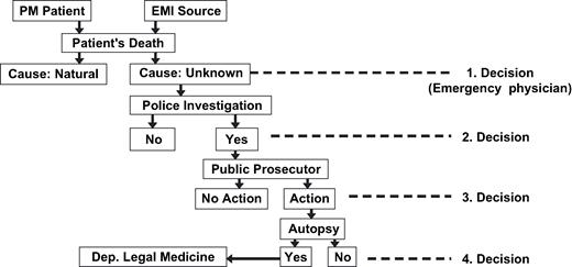
Decision tree in detecting fatal accidents of pacemaker patients in electromagnetic fields.
Principle and practice of pacemaker triggered MRI scan
What can be done to remove the risks combined with today's pacemakers in MRI units? We propose as a solution the following strategy:
Asynchronous magnet function is programmed off.
VVT mode is programmed in single or dual chamber units.
Interference mode, inhibition, or atrial synchronisation by gradient fields are excluded if scanning is triggered by the ECG or by the stimulus artefact and is restricted to the ventricular refractory period.
Possible heating of the electrode tip due to RF-pulses is reduced because the scan duration is much smaller than the pacemaker period (reduction is T (scan)/ T (PM period).
Rapid stimulation due to rectified RF-pulses is also avoided if scanning is restricted to the refractory period of the heart which should end at least when the pacemaker refractory period ends.
Feature 1 is a prerequisite for safe scan triggering. Programming of the VVT mode in feature 2 is suited also to have MRI triggering by spontaneous beats. Not all of today's pacemakers possess both features. But caution should be employed when programming the VVT mode without triggering and restricting the MRI scan to the refractory period which may be dangerous.
Fig. 3 shows the block diagram of a pacemaker triggered MRI scan. With radio translucent ECG electrodes positioned almost linearly between the apex and the right clavicle with the reference electrode lying just in the middle, the stimulus artefact is derived with the aid of a differential pre-amplifier with variable amplification. This electrode position guarantees maximum amplitudes of ventricular bipolar leads [24] with simultaneously lowest noise coupled magnetically into the measuring system. The pre-amplifier is connected to:
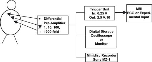
Block diagram of a pacemaker triggered MRI scan.
a trigger unit that needs an input signal of ≥0.25 V, yielding an output pulse of 2.5 V and 10 ms and having a refractory period of 400 ms,
a digital storage oscilloscope from which the stored signals can be transferred off-line to a personal computer for storing and processing the signals, and
optionally, a storage means for documenting the functionality of the triggering mode of MRI scanning (we used a Sony minidisk recorder MZ-1).
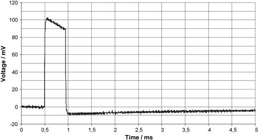
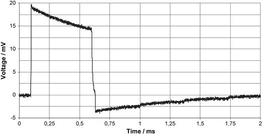
Fig. 4 shows a unipolar ventricular pulse derived with 10-fold amplification from the thorax. Fig. 5 shows a bipolar ventricular pulse with 100-fold amplification. The natural ECG, as demonstrated in Fig. 6 with an amplification of 1000, is very noisy (50 Hz) so that it is less suited as trigger signal. All voltages in Figs. 4–6 are referred to the input which means that they represent the voltage as it exists on the thorax. To extract the ECG signal from noise needs considerable filter efforts (bold line in Fig. 6 ). The stimulus artifact as trigger signal has, moreover, the advantage to precede a paced action by 40–80 ms that prolongs the interval in which scanning can take place. Fig. 7 depicts the beginning of the scan. Between pacing pulse and the first gradient pulse, RF pulses are recognizable. Fig. 8 should demonstrate that the trigger principle is also feasible in patients with AAI pacemakers. Conversion of the generator's AAI mode to AAT made triggering possible without problems. Such triggering is impossible with the ECG synchronisation. In this patient a problem arose insofar as the RR feature was initially not programmed off.
Unipolar ventricular pacing pulse derived from the thorax as described with Fig. 3 . The voltage is referred to the input.
Bipolar ventricular pacing pulse derived from the thorax as described in Fig. 3 . The voltage is referred to the input.
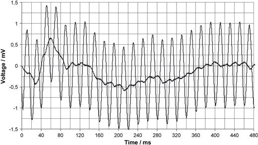
Derivation of an ECG from the thorax with (bold line) and without filtering in the noisy environment of a MRI unit (without scanning) as described in Fig. 3 . The voltage is referred to the input.
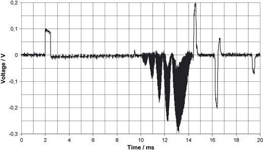
Beginning of the scan with expanded time deviation. Signals produced by RF pulses before gradient pulses are visible.
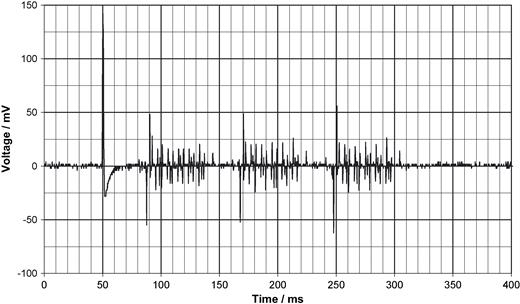
Scan triggered by an AAT mode pacemaker which prolongs the possible scan period by the AV-interval to up to 450 ms (here not used).
So far, we have carried out 12 MRI examinations in eight patients.
Discussion
Our question has revealed that life threatening situations are not associated with pacemaker dependency but with competitive rhythms originating mostly from fast magnetic rate stimulation and irregular spontaneous rhythms. Furthermore, Table 4 demonstrates that three out of the six fatal cases occurred in 0.5 T scanners which are not safer than scanners with higher induction as suggested by Vahlhaus and co-workers [10] . Indeed, pacemaker dependent patients may form the safest population for MRI examination if they are bradycardia patients with a single chamber device only, as pacemaker inhibition is very unlikely to occur. Their exclusion is based on a myth, narrated amongst radiologists since the beginning of MRI examination of pacemaker patients, and not on experimental evidence. However, short term inhibition of pacemakers in patients undergoing MRI examination has been reported in the literature without further details [8,,18,,21,,22] . We estimate that starting a new scan sequence, as described above, was responsible for this effect.
Similarly, lead and pulse generator dislodgement due to magnetic forces or reprogramming are presumed risks that were often repeated in the literature on an intellectual basis without any experimental proof.
The real life threatening risk is competitive pacing that should be avoided. This is also the reason why the “photonic catheter providing VOO functionality” [11] is not suitable to solve the MRI problem.
It is difficult to predict the behaviour of pacemakers in strong magnetic fields. Depending on orientation, between 19.4% and 72.2% of the pacemakers tested in magnet mode, are switched to the synchronous mode, though they worked in the asynchronous magnet mode in low magnetic fields. It is a surprise that 23.6% of the pacemakers with the magnet mode programmed off, nevertheless paced asynchronously. All these difficulties could be avoided if an electronic system, for instance integrating the magnetic field, replaced the mechanical system “reed contact”, as was successfully implemented in Telectronics pacemakers many years ago. Two such pacemakers, tested in 1.5 T magnetic fields, worked asynchronously in all orientations. A Hall transducer would also solve the problem but was not tested by us.
The influence of gradient fields on pacemakers is very clear on the basis of our calculations and measurements: they can cause either switching to interference mode or, less likely, to ventricular inhibition if the pulse generator works in the synchronous mode. In this mode, rapid ventricular pacing is also possible in dual chamber systems. The induced voltages are so strong that it is hard to believe that they can be filtered out, which makes the invention of an MRI resistant, but synchronous pacemaker rather improbable. Gradient fields are not capable of producing stimulating pulses, a voltage across the lead of only 29.4 mV (zero-peak) as calculated above is far below rheobase, so that even pacing by pulse trains is impossible.
Our calculation yields an explanation why Luechinger and colleagues [19] did not find in their in vivo experiments damage at the histological level nor major changes in thresholds. Heating is concentrated immediately around the surface of the electrode. It, then, sharply decreases with distance. This fact is well known in RF surgery. With smaller than 6.3 mm 2 electrodes, for which we calculated heating above, the situation is still more favourable. Thus, we can conclude that heating of the electrode(s) is not a real problem in MRI scanning of pacemaker patients.
MRI influence on battery voltage, battery current and battery resistance is not easy to determine if the output parameters are changed during or because of MRI examination. We showed that without being subjected to MRI scanning, a programmed increase in rate, or output voltage, or pulse duration of a pulse generator may reduce battery voltage or increase battery impedance, thereby reducing calculated function time. It seems to us to be very likely that the reduction in voltage observed by Vahlhaus and colleagues [10] was produced by programming the pacemakers of non-dependent patients to a rate “that suppressed intrinsic rate during the study”. Thus, it was probably programming and not MRI scanning that produced battery voltage decrease.
The proposed principle of triggered MRI scanning offers the possibility of safely examining a pacemaker patient without any risk of having stimuli within the vulnerable period, if the magnet function of asynchronous pacing can be programmed off and if this state is stable also in strong magnetic fields. Our results, however, show that this is not the case in 23.6% of the tested pacemakers. Therefore, we ask manufacturers to offer in a reliable way this programmable feature. The electronic “reed contact” such as an integrator or a Hall transducer would be an alternative. Furthermore, the VVT mode should be possible with free choice of the refractory period which is not the case in Intermedics pacemakers. If these conditions are fulfilled, today's pacemakers need no further modification to be safe with MRI scanners, if pacemaker triggered MRI scanning is carried out. The answer to the question in our title: “Do we need pacemakers resistant to magnetic resonance imaging?” is clearly: “No”. A small modification of the MRI unit and programmability of the magnet function is all that is needed to make pacemakers compatible with MRI examination. The only disadvantage of MRI triggering is that MRI session durations are prolonged by a factor which is determined by the ratio of pace period related to refractory period which is approximately three times longer.
Advantages of pacemaker triggering over ECG triggering are:
The signal is distinct above noise.
The pacing pulse is 40–80 ms in advance of a paced QRS complex, so that the scan period can be longer.
Advantage of ECG triggering, if it functions, is:
No alterations in programming and in MRI triggering are necessary, if an ECG input exists.
So far, we have carried out successfully 12 examinations in eight patients in the MRI triggered mode without safety problems. The only situation to interrupt scanning was the AATR mode of the pacemaker whose scan voltages are depicted in Fig. 8 . The noisy environment led to a rate of 110 min −1 . Therefore, our advice is to programme off all rate responsive features.
Conclusions
High gradient field voltages make invention of a synchronous pacemaker tolerating MRI unlikely.
The real danger for pacemaker patients undergoing MRI examination is competitive rhythm in the case of asynchronously pacing generators and spontaneous, sometimes tachyarrhythmic heart rhythms. It is neither inhibition of the pacemaker nor heating of the lead tip that poses a real risk.
Patients with magnet function off can safely be examined, if scanning is restricted to the refractory period of the pacemaker.
Patients with non-programmable magnet function can be examined if, and only if, spontaneous beats are absent . Patients with asynchronous pacing and tachyarrhythmias should be handled in a special way, either by careful monitoring with a defibrillator at hand or by programming the output parameters to below threshold.
Programmable magnet function, not influenced by strong magnetic fields, is a prerequisite for future pacemakers.
Pacemakers with programmable magnet function should preferably be implanted, for the benefit of patients who may later require MRI examination.
Acknowledgment
We cordially thank Mrs Dawn Merx for her valuable linguistic assistance.
