


Abstract
An electrical short circuit is a rare complication in a high-voltage implantable cardioverter-defibrillator (ICD). However, the inability of an ICD to deliver appropriate shock therapy can be life-threatening.
During the last 2 years, four cases of serious complications related to an electrical short circuit have been reported in Japan. A spark due to an electrical short circuit resulted in the failure of an ICD shock to terminate ventricular tachycardia and total damage to the ICD generator in three of four cases. Two of the four patients died from an electrical short circuit between the right ventricle and superior vena cava (SVC) leads. The others had audible sounds from the ICD generator site and were diagnosed with a lead-to-can abrasion, which was manifested by the arc mark on the surface of the can.
It is still difficult to predict the occurrence of an electrical short circuit in current ICD systems. To reduce the probability of an electrical short circuit, we suggest the following: (i) avoid lead stress at ICD implantation, (ii) select a single-coil lead instead of a dual-coil lead, or (iii) use a unique algorithm which automatically disconnect can or SVC lead from shock deliver circuit when excessive current was detected.
This report is the first to describe the mechanisms of short electrical short circuit in high-voltage devices.
Short electrical short circuit is a rare complication, but life-threatening when it developed.
Moreover, it is unfortunately unpredictable before the device discharge a high-energy current against ventricular tachycardia.
All we can to do to prevent from this complication: (i) avoid lead stress at ICD implantation, (ii) select a single-coil lead instead of a dual-coil lead, or (iii) use a unique algorithm called DynamicTX.
Introduction
A high-voltage (HV) device electrical short circuit in a HV implantable cardioverter-defibrillator (ICD) is a serious complication, because it is usually accompanied by failure to deliver shock therapy. There are two main mechanisms of electrical short circuit: (i) abrasion between the can and HV lead conductor, and (ii) lead insulation failure between the right ventricle (RV) and superior vena cava (SVC) coil conductors. The incidence of HV device electrical short circuits is quite low.1,2 However, in Japan, four cases of such complications occurred during the last 2 years. In this report, we discuss four cases of electrical short circuit and review the related literature.
Case 1
A 53-year-old woman with a history of malignant lymphoma was rescued from ventricular fibrillation (VF) by an AED in 2007. A dual-chamber ICD (Marquis DR, Medtronic, Minneapolis, MN, USA; CapSure Fix Novus/5076, Medtronic; RIATA 1580, St Jude Medical, Sylmar, CA, USA) was implanted. The device detected VF in July 2008 and was terminated successfully after delivery of the first ICD shock. The ICD was later replaced with a Secura DR (Medtronic) in November 2010 due to battery depletion. The last follow-up of the patient occurred in August 2011, where impedance values were stable and measured impedances of the RV and SVC coils of 46 and 55 Ω, respectively. No electrical abnormality of the system was observed during follow-up. In December 2011, the patient was later found on the street in cardiopulmonary arrest. She was transported to the nearest hospital and later expired. The ICD device and a portion of the RV lead were explanted and returned to the respective manufacturers for further examination. Figure 1 shows the therapy log from the explanted device. The cause of death was determined to be VF. The device diagnosed VF and attempted to deliver shock therapy; however, therapy was not delivered due to a low impedance measurement. The device diagnosed VF again and attempted to deliver a second shock. However, the second shock was also interrupted and failed to provide appropriate therapy. This sequence occurred six times. All of the shocks were interrupted by the excessive current protection system and after the sixth failed shock delivery attempt, the device did not provide further therapy. The manufacturers examined the returned device and lead. An arc mark was not found on the device body, and no mechanical or electrical abnormality was observed within the partially extracted leads. We speculate that the excessive current most likely occurred by electrical short circuit in the insulation between the SVC and RV coil conductors.
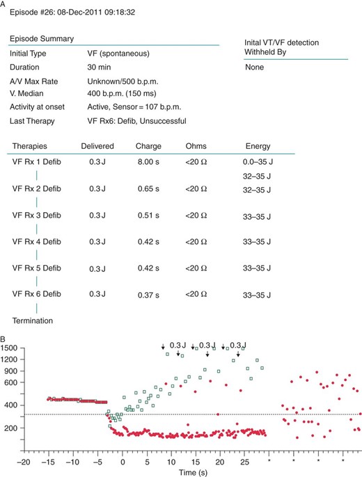
(A) Episode summary revealed that VF detection occurred; however, the capacitors were charged to 32–35 J, but only 0.3 J was delivered due to the excessive current protection system. (B) Ventricular fibrillation could not be terminated by 0.3 J shocks (black arrows) and it continued for 30 min.
Case 2
A 42-year-old male was implanted with an ICD in November 2001 after being diagnosed with idiopathic VF. An ENDOTAK ENDURANCE #0134 (CPI Inc., St Paul, MN, USA) was chosen as the ICD lead. In July 2002, the ICD delivered its first shock and was successful in terminating VF. Amiodarone was administered due to the increasing number of delivered shocks subsequent to the first shock delivery. The ICD device was later replaced in 2004. During the time of replacement, sensing failure occurred and a new RV pacing lead was implanted while the RV coil of the ICD lead remained in continuous use. In July 2010, a second device replacement was performed and a Lumax 540-DR (Biotronik, Berlin, Germany) was implanted. After this replacement, a remote monitoring system was utilized to send patient data to the remote monitoring centre in Berlin, Germany. In May 2012, the data that were sent via the remote monitoring system exhibited no abnormalities with an impedance reading of 68 Ω (Figure 2). At 6:00 a.m., the patient's wife noticed something was wrong with the patient and requested an ambulance and tried to resuscitate him. An electrocardiogram (ECG) was obtained in the ambulance, which demonstrated VF. An external defibrillation shock was delivered, but was unsuccessful. The patient was transported to the emergency room at the local hospital, but expired en route. Device interrogation was attempted; however, the programmer could not communicate with the device. The device was later explanted and returned to the manufacturer for evaluation. The lead was not explanted. The manufacturer's analysis report showed that the device surface was intact but the HV switching circuit in the device can was destroyed (Figure 3).
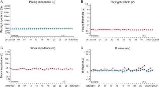
According to the Cardio Messenger Home Monitoring System, the last data were sent at 0:53 in May 2012. No abnormality was detected in the following: (A) pacing impedance (Ω), (B) pacing threshold (V), (C) shock impedance (Ω), or (D) R wave (mV).
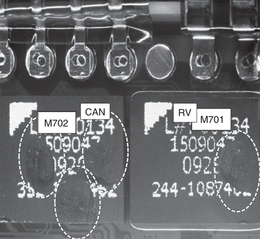
In an explanted Lumax 540-DR, the output switch circuits of both the can (three left circles) and RV lead (right circle) were partially melted. This phenomenon indicated electrical overload from abnormal temporary high current along the component of the electrical circuit. In this case, the origin of the high current was not clear. The surface of the ICD was intact, and further analysis by Biotronik showed that the device was free of short circuits in the shock path. There was highly unlikely of an intra-pocket short circuit, because there was no arc mark on the surface of the device. Therefore, it was assumed that an external short circuit had taken place within the leads during delivery of shock therapy that damaged the ICD.
Case 3
A 39-year-old male, who had a family history of sudden cardiac death, was referred to a university clinic because of palpitations. His ECG demonstrated a coved-type ST elevation, and polymorphic ventricular tachycardia was induced by double premature stimulation during the EP study. Therefore, an ICD (Guidant VENTAK PRIZUM2 DR, Guidant (Boston Scientific), St Paul, MN, USA; ENDOTAK ENDURANCE EZ #0154; Guidant (Boston Scientific)) was implanted in 2004. In May 2011, a device replacement was performed along with defibrillation threshold (DFT) testing. During DFT testing, VF was induced by a 2 J shock on the T wave and after VF detection, the device delivered a 14 J shock, which was programmed. However, the VF was not terminated and an audible ‘popping’ sound was noted. An external shock was administered and the VF was finally terminated. Immediate interrogation of the device was attempted but was unsuccessful, and a short-circuit alert was indicated on the programmer screen. After further review of the ICD lead, an insulation failure was found. The lead failure occurred not only on the silicone outer insulation, but also on the ethylene tetrafluoroethylene (ETFE) of the RV coil conductor (Figure 4).
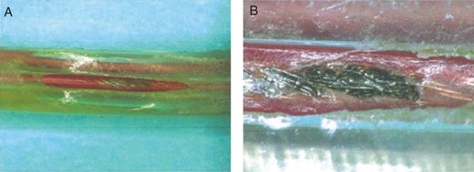
(A) An extracted ICD lead showed partial insulation defect that developed from arc discharge. (B) The lead failure occurred not only on the silicone outer insulation, but also on the ETFE of the RV coil conductor.
Case 4
A 32-year-old woman with DCM was implanted with an ICD system (ICD lead: 6945 SPRINT, Medtronic; atrial lead: SELUTE AJ, ICD device, Boston Scientific) in 2004. The device was later replaced in October 2011. During the replacement procedure, the ICD and atrial pacing leads were found to be located in front of the device. The atrial and ICD lead were dissected from the fibrous tissue in the device pocket and placed behind the device. DFT testing was not performed after the procedure. In June 2012, the patient was awoken by a loud, clapping sound inside the device pocket; and she felt pain in the location where the device was located, followed by an audible noise coming from the device. The following morning, she visited the clinic, and a physician attempted to interrogate the device. However, the interrogation was unsuccessful, and a warning was displayed on the programmer's monitor. An emergency operation was performed, and insulation failures on the ICD lead and atrial lead were observed. Inspection of the lead body showed the presence of a distal slit. The atrial lead demonstrated failure due to a lead-to-can abrasion. An arc mark was observed on the device surface near the area where the ICD lead failed (Figure 5). Multiple thermal burns around the device were also observed.
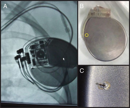
(A) A preoperative X-ray revealed no significant abnormalities in either lead. However, multiple burns and areas of bleeding were found within the excised ICD pocket during operation. We found a surface arc mark on the back of generator, which suggests a HV electrical short circuit (B and C). The arc mark was due to stimulation from outside the body, because an injury did not occur inside the body. On the X-ray, the arc mark was located near the slit in the ICD lead, while far from the slit in the atrial lead. Moreover, the generator could not be destroyed due to an artificial slit in the atrial lead during a bench test. Thus, we concluded the arc mark was due to ICD lead failure.
Discussion
High-voltage electrical short circuits cause the interruption of shock delivery, thus causing ICD failures or burns in the device pocket. These ICD shock failures result in the failure of the device to deliver appropriate therapy to terminate arrhythmias such as VF. In our four cases and in three previous case reports,3–5 HV electrical short circuits were found when shock delivery failed. The failure to deliver therapy can be life-threatening. In our Case 3, along with Leong and van Erven3 and Goldstein et al.'s5 cases, the patients were in the hospital when VF occurred. External defibrillators were utilized, and these patients were rescued. In Shah et al.'s4 case and our Cases 1, 2, and 4, the patients were not in the hospital at the time of VF. In Shah et al.'s4 case, the shock was inappropriate because the device failed to recognize supraventricular tachycardia as ventricular tachycardia, and therapy was not needed. The supraventricular tachycardia spontaneously terminated and therefore was not a life-threatening event. Unfortunately, in Cases 1 and 2, the failure to deliver shock therapy resulted in the death of the patients.
Insulation failure between RV and SVC coil conductor
In Cases 1 and 2, the device pockets did not show any evidence of an HV electrical short circuit such as an arc mark on the can, and therefore, it is believed that the electrical short circuit occurred inside of the lead. In three previously reported cases,3–5 evidence of an HV electrical short circuit was also not observed in the device pocket. If the short circuit originates from inside the lead, it is suspected that both the HV conductor or the RV coil conductor and the SVC coil body came in direct contact. The HV electrical short circuit typically develops from the device pocket to the distal end of the SVC coil, where the HV anode and cathode are located close together. However, if an HV electrical short circuit occurs inside of the lead, it is difficult to detect because there is no physical evidence of such a short. Therefore, this type of electrical short circuit can only be proved by lead extraction and further analysis of the lead. Unfortunately, the ICD leads were not extracted in the previously reported cases, or in our Cases 1 and 2.
Abrasion between can and high-voltage lead conductor
In Cases 3 and 4, the outer lead insulation demonstrated lead-to-can abrasion. Lead insulation failure is one of the primary factors responsible for HV device electrical short circuits. The abrasion reached the ETFE sheath, which was the insulation material used to protect the RV coil conductor. In a previous case report by Diez et al.,6 the HV electrical short circuit was caused by an electrical short between the device can and the RV coil conductor. Moreover, multiple insulation failures which caused lead-to-can abrasions were also detected. Our Case 4 revealed a burn in the device pocket and multiple insulation failures. One of the failures occurred with the atrial pacing lead, and the failure of this lead was also caused by lead-to-can abrasion similar to that described by Diez et al.6 The other insulation failure was due to a slit in the ICD lead. In addition, there was an arc mark on the device located near the slit in the ICD lead. This slit-like insulation failure was the probable cause of the device electrical short circuit.
How to detect lead insulation failure
Regular impedance measurements to determine whether an electrical short occurred may not be sufficient. The measured impedances and pacing thresholds were unchanged before shock delivery in Case 2 and DFT testing in Case 3 (Figure 3). Leong and van Erven3 and Goldstein et al.5 also confirmed that there were no electrical abnormalities in the system prior to the failure of shock delivery. Therefore, we can assume that the conductors did not come in contact before the DFT test. The photograph of the device shown in the report by Diez et al.6 contained many arc marks, which were caused by a spark discharge. If a spark discharge caused an HV device electrical short circuit, the HV device components do not come in contact with each other, which can be verified by the lack of impedance changes.
Noise from the pace/sense lead is not always the main causes of inappropriate device shock therapy, but there is also the possibility of abnormal contact with any other HV conductor. In the case reported by Goldstein et al.,5 there was inappropriate shock therapy and an HV short circuit. In this case, the pace/sense conductor fracture was associated with the insulation failure of the HV conductor. Goldstein et al.5 might not have performed DFT testing if inappropriate shock therapy did not occur; thus, the insulation failure of the HV conductor might not have been detected. This case suggests that multi-conductor failure should be excluded if an inappropriate shock is caused by over-sensing. Gunderson et al.7 developed an algorithm to identify ICD lead failures. They concluded that over-sensing combined with abnormal impedance trends might be used to identify ICD lead failures with a sensitivity of 83% and specificity of 100%. Swerdlow et al.8 evaluated the algorithm and suggested that it might be able to reduce inappropriate shocks caused by lead fractures. However, this algorithm does not seem to detect short circuits caused by a spark discharge.
Kleemann et al.2 pointed out that the percentage of insulation failures of ICD leads increases with each passing year after ICD implantation. The failure ratio was 15% in 934 average observation days. However, only coaxial ICD leads were included in this dataset. Borleffs et al.9 reported that the failure rate when coaxial leads were excluded was 3.8% at 36 months after ICD implantation, and the estimated failure rate at 10 years post-implant was 16.4%. Coaxial ICD leads are known to have a poor longevity, and the number of coaxial leads in use has been decreasing. However, there has been an increase in the use of multi-luminal ICD leads, resulting in a higher rate of lead insulation failure.
The best way to prevent shock delivery failure
Although it is still challenging to overcome shock delivery failure due to a short electrical circuit, three options are recommended with current ICD systems. At first, to avoid lead stress, a cephalic vein cut-down or extra-thoracic puncture during ICD implantation will protect the lead from insulation failure. These procedures are fundamental and extremely important because most multiple conductor failures are located inside the device pocket or near the sub-clavicle area and susceptible to the so-called sub-clavicle crush syndrome. Additionally, most of the lead outer insulation is made of silicone. This silicone material can easily be compromized by a stick with a surgical needle and therefore caution should always be exercised in/around silicone-coated leads. Moreover, most of the HV device short circuits occur after device replacements, as shown in our four cases and previous reports.3,5 Caution should be exercised as not to cause physical stress to the implanted leads during device replacement procedures. Secondly, a single-coil system has an advantage over a dual-coil system for preventing HV device short circuits, because a single-coil system only has one HV conductor inside of the ICD lead. On the other hand, a dual-coil system has two HV conductors inside of the ICD lead. The number of HV conductors is an important factor that contributes to lead failure. The SVC coil conductor plays an important role in HV device short circuits in dual-coil systems. Choosing a single-coil system is a simple and safe strategy for an ICD recipient without a high DFT to prevent HV device short circuits induced by abnormal contact between the RV and SVC coil. When a patient is implanted with a dual-coil system, the SVC coil can be disconnected from the HV system by the programmer. Although we should note that this feature is not universally available and is only available from some ICD manufacturers, the patients may still have been alive in our Cases 1 and 2 if the SVC coil had been disconnected. In a single-coil system, the HV device short circuit occurs only in the device pocket.
Finally, a unique algorithm called DynamicTX from St Jude Medical, Inc. is quite useful to prevent HV short circuits. If an HV short circuit is detected, the excessive current prevention system interrupts the delivery of shock therapy. The DynamicTX algorithm automatically disconnects the SVC coil while the system is recharging. The shock therapy is delivered again utilizing the can-to-RV coil vector. If the short circuit exists in the device pocket, the DynamicTX excessive current prevention system then disconnects the can from the shock system. Then, a shock is delivered using the SVC-to-RVC shock vector. Many studies were performed to evaluate the efficacy of this shock vector.10–12 This DynamicTX algorithm seems to be an effective solution to prevent HV device short circuits with aging ICD leads.
Conclusion
In this report, we describe four cases of electrical short circuit in an ICD. In all of our cases, this complication developed following the device's high-energy discharge without any warning sign of abnormal lead impedance or shock impedance. More advances of high-voltage devices and leads are expected to avoid this tragedy for ICD recipients.
Conflict of interest: none declared.
References
Author notes
This study complied with the guidelines of the declaration of Helsinki and was approved by the institutional review board of Gunma University Hospital. All patients granted their written, informed consent before participation in this study.
These authors contributed equally.
