


Abstract
Our aim was to evaluate the potential for safely imaging patients with a new type of implantable cardioverter-defibrillator called the subcutaneous implantable cardioverter-defibrillator (S-ICD) in a 1.5 T magnetic resonance imaging (MRI) scanner. With the increasing number of patients with cardiac implantable devices who are indicated for MRI, there is a growing need for establishing MRI compatibility of cardiac implantable devices.
Patients with implanted S-ICD systems underwent one or more types of anatomical MRI scans. The S-ICD was programmed off and patients were monitored throughout the imaging procedure. Device function was evaluated pre- and post-scan. Patients were asked to report immediately any pain, torqueing movement, or heating sensation in the area of the pocket or electrode. Fifteen patients underwent a total of 22 examinations at 1.5 T. Scans included brain, spine, knee, and heart. Two patients were re-scanned due to complaints of heating over the can during lumbar scans, which was caused by a thermistor probe placed on the skin to measure skin temperature. All the remaining scans occurred without incident. No evidence of device malfunction was observed.
This study is the first to domonstrate the feasibility of exposing S-ICD patients to MRI using the scanning and monitoring protocol described. More data are required to support S-ICD as a MRI conditional device.
This study is the first to exam S-ICD as a MRI conditional device.
Introduction
The need for magnetic resonance imaging (MRI) in patients with an implanted pacemaker or implantable cardioverter-defibrillator (ICD) is a growing clinical issue. It is estimated that as many as 75% of active cardiac device recipients will become indicated for MRI.1 Currently, the vast majority of such devices are contraindicated for use with an MRI.2 In European Heart Rhythm Association survey, published recently for non-MRI-certified ICDs (0.5–1.5 T field strength), MRI was considered possible in only 13.2% of all responders.2 The totally subcutaneous ICD (S-ICD) system, an implantable defibrillator with no leads that touch the heart, has recently been demonstrated to be a safe and effective defibrillator option for patients at risk for sudden cardiac death.3–6 It provides shock therapy and post-shock pacing therapy, but no long-term bradycardia pacing. Although it has been shown as an alternative to the standard transvenous ICD, its compatibility with MRI remains unclear.
Various types of clinical MRI systems currently use a superconductive magnet that creates a static magnetic field strength, typically 1.5 or 3 T.7 The use of MRI with most pacemakers and ICDs is considered a contraindication due to potential hazards, including heating of the electrode that resides in or on the heart, damage to myocardium, elevation of pacing thresholds, unintended induction of ventricular tachycardia (VT) or ventricular fibrillation (VF), pacing inhibition, permanent device malfunction, and distortion of the MRI scan. Recently, a few active cardiac devices have established the indication of being ‘MR-conditional’. MR-conditional indicates a lack of known hazards in a specified MRI environment with specified conditions of use.8 Due to the variety of MRI scanners and scanning protocols, it is not practical to test even a single device under all conditions. Hence, MR-conditional labelling dictates that the device is safe for use under certain scanning conditions, as well as how the cardiac device should be programmed before an exposure to the magnetic field in a MRI scanner.
The literature, although limited, provides some guidance for imaging patients with implanted pacemakers or ICDs that do not have MR-conditional labelling.9,10 This single-centre prospective non-controlled study describes the first use of MRI in patients with an implanted S-ICD.
Methods
Patient selection
Patients with implanted S-ICD systems (Boston Scientific SQRx Model 1010 and Q-TRAK Model 3010) were enrolled for MRI testing over a period of 18 months. The S-ICD system implanted in this patient cohort was composed of a can implanted in a left mid-lateral pocket and a para-sternal subcutaneous electrode. The S-ICD is currently not certified for use with an MRI; therefore, the Ethics Committee of Homolka Hospital, Prague, Czech Republic approved our clinical study. Patients with newly implanted S-ICD systems (<6 weeks) were excluded, and none of the patients had any intravascular leads. The patients were randomized for either a cardiac, brain, cervical, or lumbar spinal scan. One of the subjects underwent an additional knee examination, due to reported chronic pain. A total of 15 patients were enrolled into this study (12 males and three females, aged 22–83 years, mean 53 years. Body mass index (BMI) 20.5–39.9; mean 26.7). Subjects in our cohort (Table 1) underwent a total of 22 MRI scans between 6 June 2012 and 24 December 2013. In total, five brain scans, three cardiac scans, 12 lumbar scans, one knee, and one cervical spine scan were conducted (Table 2). There was not a specific requirement for an MRI—no direct clinical indication. However, in one patient a minor disc protrusion was found, in other MRI revealed stenosis of intervertebral foramen which was causing radicular pain of the nerve root L4 and based on this examination the patient was referred to CT-navigated periradicular therapy. All patients gave written informed consent.
Summary of patient anatomical data and scan locations, along with noted clinical events
| ID | Age | Sex | BMI | Dg | EF, % | Indication for S-ICD | Heating |
|---|---|---|---|---|---|---|---|
| 01 | 64 | F | 20.5 | HCMP/VFs | 85 | Secondary prevention | None |
| 02 | 83 | M | 30.0 | Post-MI/SMVTs post-catheter ablation/ | 35 | Secondary prevention (post-transvenous ICD extraction) | None |
| 03 | 31 | M | 25.3 | ARVC/D/SMVTs | 68 | Secondary prevention | In-tolerable re-scanned |
| 04 | 58 | M | 23.6 | Post-MI/post-CABG | 30 | Primary prevention | None |
| 05 | 77 | M | 25.5 | Post-MI | 30 | Primary prevention | None |
| 06 | 63 | M | 27.0 | Post-MI | 30 | Primary prevention | None |
| 07 | 68 | M | 23.7 | Post-MI/VFs/VTs | 60 | Secondary prevention post-transvenous ICD extraction/SVC occlusion | Tolerable |
| 08 | 22 | M | 29.4 | Brugada sy/VFs | 68 | Secondary prevention | In-tolerable re-scanned |
| 09 | 59 | M | 27.1 | DCMP/VFs/post-mitral valve surgery/ | 60 | Secondary prev./post-transvenous ICD extraction | None |
| 10 | 41 | F | 24.6 | ARVC/D | 70 | Primary prevention | None |
| 11 | 23 | F | 21.5 | LQTS/VF | 60 | Secondary prevention | None |
| 12 | 66 | M | 36.9 | Post-MI/VF/post-CABG | 50 | Secondary prevention/post-repeat transvenous ICD extraction | Tolerable |
| 13 | 48 | M | 22.9 | DCMP(non-compaction)/VFs | 35 | Secondary prevention | None |
| 14 | 70 | M | 29 | Systolic dysfunction of LV | 35 | Primary prevention | None |
| 15 | 26 | M | 33 | Brugada sy | 65 | Primary prevention | None |
HCMP, hypertrophic cardiomyopathy ; SMVT, sustained monomorphic ventricular tachycardia; MI, myocardial infarction; ARVC, arrhythmogenic right ventricular cardiomyopathy; CABG, coronary artery by-pass graft; LQTS, long QT syndrom.
Parmeters of S-ICD and patient sensation during individual MRI scans
| Scan # | ID | Body part | Heating sensations | Shock zone (b.p.m.) | Condit. shock zone (b.p.m.) | Bat % | Episode num. |
|---|---|---|---|---|---|---|---|
| 1 | 01 | Brain | None | 230 | 210 | 100 | 1 |
| 2 | 02 | Brain | None | 240 | 220 | 86 | 1 |
| 3 | 03 | L spine | In-tolerable | 240 | 220 | 83 | 1 |
| 4 | 03 | Brain | None | 240 | 220 | 83 | 1 |
| 5 | 04 | Brain | None | 220 | 190 | 69 | 1 |
| 6 | 05 | L Spine | None | 220 | 210 | 54 | 1 |
| 7 | 06 | L Spine | None | 240 | 220 | 68 | 1 |
| 8 | 07 | L Spine | Tolerable | 240 | 220 | 58 | 2 |
| 9 | 08 | L spine | In-tolerable | NA | NA | NA | NA |
| 10 | 08 | Brain | None | NA | NA | NA | NA |
| 11 | 08 | L spine | None | 230 | 210 | 84 | 1 |
| 12 | 09 | Heart | None | 240 | 220 | 89 | 1 |
| 13 | 10 | L spine | None | 230 | 180 | 79 | 1 |
| 14 | 10 | Heart | None | NA | NA | NA | NA |
| 15 | 11 | Heart | None | 230 | 190 | 97 | 1 |
| 16 | 12 | L spine | Tolerable | 200 | 170 | 97 | 2 |
| 17 | 12 | L spine | None | 200 | 170 | 94 | 2 |
| 18 | 13 | C spine | None | 230 | 190 | 100 | 4 |
| 19 | 13 | L spine | None | 230 | 190 | 100 | 4 |
| 20 | 14 | L spine | None | 230 | 190 | 86 | 1 |
| 21 | 15 | Knee | None | 250 | 210 | 100 | 1 |
| 22 | 15 | L spine | None | 250 | 210 | 100 | 1 |
S-ICD parameters acquired prior- and post-MRI were without any change, therefore only one value is presented.
Indices: NA, not available; L spine, lumbar spine; C spine, cervical spine.
Magnetic resonance imaging
Studies were performed using a Siemens Avanto 1.5 T MRI scanner (VB17 software, Quantum gradient coils). All scans were run in normal operating mode, which is limited to 2 W/kg whole body averaged specific absorption rate (SAR). Clinically relevant MRI sequences were used for evaluation (see Table 3).
Types of pulse sequences typically used for imaging of respective anatomical areas
| Scan location | Scan sequences | |||||||
|---|---|---|---|---|---|---|---|---|
| FLAIR | DWI | FLASH | FSE | HASTE | SE | STIR | TrueFISP | |
| Brain | X | X | X | X | ||||
| Heart | X | X | X | X | ||||
| Cervical Spine | X | X | ||||||
| Knee | X | X | X | X | ||||
| Lumbar Spine | Xa | X | ||||||
FLAIR, fluid attenuated inversion recovery; DWI, diffusion weighted imaging; FLASH, fast low angle shot; FSE, fast spin echo; HASTE, half acquisition single-shot turbo spin echo; SE, spin echo; STIR, short Tau inversion recovery; TrueFISP, true fast imaging with steady-state precession.
aFSE sequence caused heating in subjects with a thermistor probe during lumbar spine examination (see the text for details).
Patients were asked to report immediately any pain, torqueing movement, or heating sensation in the area of the pocket or the electrode by pressing an emergency bulb. Furthermore, all patients were questioned immediately following the MRI procedure to ascertain any discomfort in the vicinity of the can or electrode. Pulse oximetry and standard lead electrocardiogram (ECG) were used to monitor the presence of any arrhythmia during the scanning. An external defibrillator was readily available for immediate use. If discomfort occurred, the patient was asked if the scan could be repeated at a later time using a revised scan sequence or the subject was again randomized for another anatomical area.
Device assessment
Since none of the components of the S-ICD system are on or in the heart, heating near or around the electrode cannot harm the myocardium. However, heating near the electrode or can with the S-ICD system may still cause serious patient discomfort. Therefore, along with education of subjects, each patient was instrumented by taping an oesophageal temperature probe (beta-THERM model G22K7MCD8) on the skin over the mid-lateral implant site to record any temperature excursions that might be correlated to patient symptoms of heating/discomfort near the pocket. To minimize the risk of inappropriate therapy, the S-ICD system was programmed to therapy ‘off’ for the testing. Each S-ICD system was evaluated prior to and immediately after the scan to verify proper functioning, including interrogation, sensing, and battery voltage. After the completion of the MRI, the S-ICD system was reprogrammed to original settings. Long-term regular clinical follow-up and checking of the device were performed.
Results
No anomalies were noted via pulse oximetry or ECG during the scans for any of the patients. Eleven of 15 patients reported no sensation or pain from heating of the can, two of 15 patients reported feeling some heating, and two patients reported intolerable heating (see Table 2). In patients with intolerable heating, the scan was halted within seconds and changed to a scan of the brain, which proceeded without incident. Patient reports of heating in the vicinity of the can occurred only during lumbar scans with a thermistor probe; no such reports occurred during scans of the brain, cardiac area, cervical spine, or without the probe. In two cases where heating in the vicinity of the can was reported by the patient, the scan sequence was altered to reduce the intensity of radiofrequency (RF) field exposure by reducing the turbo factor (e.g. from 21 to 7), increasing the repetition time (e.g. to >4000 ms), and reducing the flip angle (e.g. from 170° to 120°). The target values were chosen arbitrarily to maintain image contrast (flip angle) and keep scan time at reasonable limits (turbo factor and repetition time). Less heating was noted by patients after these modifications to the scan parameters were made. One patient who only reported heating after the lumbar scan had completed (subj. 03) was observed to have a skin lesion, appearing to be a circular rash or ulcer on the surface of the skin over the can, approximately 3–5 mm in diameter. The cause of this skin anomaly is not known; it was later noted to have fully healed at a follow-up 10 days after the scan.
To ascertain the effect of heating due to the instrumented thermistor catheter, the two patients who experienced the heating (examinations 9 and 16, see Table 2) were rescanned several weeks later without the thermistor catheter in place (examinations 11 and 17). First, modified sequence (with even lower amount of energy deposited in the tissue) was used, which caused no heating. As no sensation was reported by the subjects, they were asked to report even a minimal discomfort, and the lumbar scans were performed using the same settings that resulted in heating with the thermistor catheter in place in the first imaging session. The results of the rescans revealed that no heating was felt by the patients when the thermistor catheter was absent.
Subcutaneous implantable cardioverter-defibrillator status
All S-ICD systems were interrogated immediately after the scan. There were no noted changes to battery voltage, ability to detect the QRS signal or stored diagnostic data. Pacing thresholds cannot be assessed by the S-ICD system, so this was not evaluated. None of the patients reported any pulling or twisting of the can or pain from heating of the S-ICD electrode.
Image artefacts
For scans of the brain, lumbar spine, knee, and cervical spine, no effect from image artefact was noted in the anatomical area of interest. However, for scans of the cardiac area, image artefact was noted to interfere with the ability to see parts of the left ventricle, though the right ventricle of the heart was unaffected and could be imaged usefully. This was due to the can and not the electrode (see Figure 1), modifications to the protocol for the lumbar spine resulted in a lower signal-to-noise ratio; however, the images remain in diagnostic quality (see Figure 2).
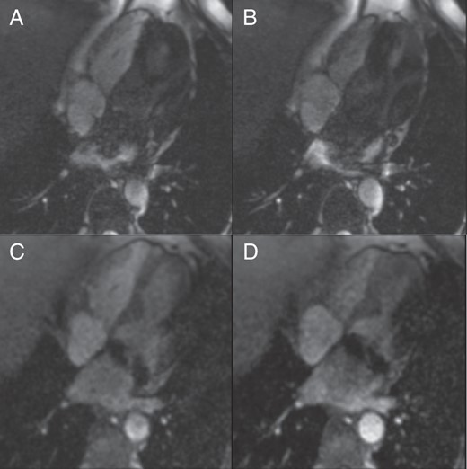
Kinetic study in four-chamber view: The systolic (A and C) and diastolic (B and D) images of cine sequences, four-chamber view. The steady-state free precession (SSFP) sequence (A and B) shows more artefacts. The patient underwent mitral valve repair with a metallic ring implantation. In SSFP kinetic study, an inflow of dark blood from the left pulmonary veins was seen. It could be caused by S-ICD but also by metallic ring in mitral annulus. The spoiled gradient echo (GRE) sequence (C and D) is better, but an artefact at the lateral wall is obvious.
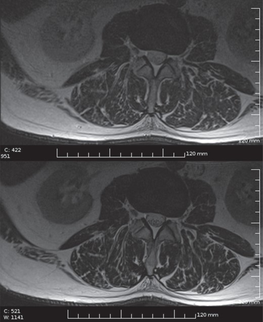
Lumbar spine imaging with ICD: low SAR T2 FSE sequence (upper image) compared with normal T2 FSE in the same subject (lower image, for the scanning parameters see the Discussion section).
Discussion
There are several reports in the current literature about MR-conditional pacemakers from several companies,11–13 but very limited reports about MR-conditional ICDs.14 Biotronik announced in late 2011 release of their first MR-compatible ICD device and defibrillator leads Pro MRI®, but in the Conditions of Use excluded scanning of the torso and focused more on the extremities examination.15 In European Heart Rhythm Association survey, 60% of centres did not implant any MRI-certified ICDs, 34.3% implanted <10 ICD devices, and only 5.6% implanted 10 and more ICDs; one-fifth of responders stated that MRI-certified ICDs should be implanted in all patients but lack of reimbursement was indicated as a possible obstacle to implant more MRI-certified pacemakers/ICDs by 47.1% of responding centres.2
None of the components of the S-ICD system are on or in the heart. The S-ICD depends less upon being in direct contact with the myocardium to function and instead uses far-field sensing and stimulation to provide the shock and post-shock pacing therapy. As a consequence, unlike transvenous systems heating near or around the electrode cannot harm the myocardium, which could present with possible safety consequences such as an elevation in pacing thresholds or scarring of the myocardium, but it may still cause serious patient discomfort. Because the S-ICD is larger than modern transvenous ICD's, there may be more potential for the can to experience heating due to the magnetic gradient or RF field.
We report results from what we believe is the first experience of MRI scanning in patients with an implanted S-ICD and in various anatomical areas. Overall, MRI was performed safely in all patients, which is in contrast to the current literature with MRI imaging in patients with electrical-active devices which are not MRI-conditional.16 In our study, the primary clinically significant event attributable to the MRI scan was the occurrence of heating in the area of the pocket in the four patients that underwent lumbar scans. It was not known if this was due to the S-ICD can itself or an artefact of the thermistor catheter used to measure skin temperature over the pocket.
This required a revision of our protocol, which was to re-scan two of the patients who complained of heating. Re-scanning of these patients without the thermistor probe resulted in no complaints of heating, so it is assumed that the thermistor catheter itself heated during the lumbar scans and caused the discomfort. As further evidence, all the heating complaints occurred during RF-intensive scan sequences (namely fast spin echo) with the temperature probe located axially near the centre of the bore, where RF fields are the highest. The thermistor catheter is constructed of insulated conductive cables connected to electrodes and should couple to the RF fields efficiently, causing heating at the electrodes and pain or damage on the surface of the skin where the probe was placed over the S-ICD can. If the heating was due to the S-ICD can itself, it would more likely occur during gradient-intensive scan sequences (which can generate eddy currents on can surfaces and internal components17) and at locations in the bore where there are high gradient fields, such as near the bore edges.18 However, when the patient was scanned with gradient-intensive scan sequences (e.g. FLAIR DWI) and with the S-ICD system in high gradient field locations in the bore (e.g. such as during a brain scan), patients did not detect any heating or discomfort. In addition, the subcutaneous lead, which was not instrumented with a thermistor catheter, never resulted in any heating sensation noted by the patient, even when exactly the same sequence that resulted in heating in the first session was used. The use of MRI-compatible temperature monitors such as fibre optic temperature probes would have provided better confirmation of possible skin temperature elevation and would not have been affected by the RF fields.
For cardiac imaging, the main problem to solve is metallic artefact, especially on the gradient-echo sequences.19 Like in research performed by Nazarian et al.,9 several scan protocols were used to see if any yielded different effects or reduced the qualitative extent of artefact. Gradient mode was changed from Normal to Whisper, resulting in slower ramping of the field and therefore diminishing the changes of the magnetic field in time. Artefacts when present were limited to blurring of the left ventricle during cardiac scans and most yielded clinically useful information.
The protocol specified programming of the therapy to the OFF mode. Standard interrogation of the S-ICD revealed no adverse effects upon the functioning of the system. While no adverse effects upon the post-scan S-ICD device function were noted, not all possible scanning protocols were tested. It should be noted that, four of the S-ICD's were exposed to repeat MRI scans without adverse effects to device function. In addition, because the S-ICD does not provide long-term bradycardia pacing, it is assumed that pacemaker-dependent patients would not be implanted with this system. The inhibition of the pacemaker function during the scanning sequence and possible pacing threshold changes are a unique concern in patients implanted with transvenous ICDs.8–10
Limitations
This study included only 15 patients and 22 scans done on the same 1.5 T MRI scanner. Thus, even these preliminary results should only be applied to 1.5 T MRI scanners (similarly as reported in the present literature for other implantable devices). Device functionality was tested immediately after the scan but not for long-term effects. In addition, not all device functions were tested although the S-ICD system does have a beeper/interrogation warning if battery levels or memory irregularities occur. However, patients were scheduled for regular check-up and no defect of the device was observed in following 7–25 months (mean observation time 18 months).
Delayed enhancement MRI for determining cardiac scarring was also not tested. This needs to be evaluated in a subsequent study. Also, there are other anatomical areas that were not evaluated, such as shoulder and knees.
Conclusions
While more data are required to support a claim of MRI-conditional, this study is the study to demonstrate the feasibility of exposing S-ICD patients to MRI using the scanning and monitor protocol described, with some precautionary measures including: (i) programming the device therapy OFF; (ii) limiting the SAR to 2.0 W/kg; (iii) continuous monitoring of the patients pulse oximetry and ECG by qualified personnel and especially for any feelings of heating; (iv) evaluate device function post scan; (v) availability of full resuscitation facilities at the MRI site. Given the variables of different MRI scanners, the decision to perform MRI on patients with an implanted S-ICD system should be balanced against the potential risks. In our study, the only heating was very likely introduced by not fully MRI-compatible thermometer probe; subjects rescanned without the probe did not report any abnormalities during the scan of any body area listed (brain, cervical and lumbar spine, heart, and knee).
Funding
This study was supported by IGA MZ ČR NT12094/2011, Research Project Charles University in Prague, PRVOUK P34 and UNCE 204010/2012. Funding to pay the Open Access publication charges for this article was provided by IGA MZ ČR NT12094/2011.
Acknowledgements
The authors thank Brendan Koop and Richard Sanders from Boston Scientific for their assistance in the preparation and review of this manuscript and Martina Goldbergova for study coordination.
Conflict of interest: None declared.
