-
PDF
- Split View
-
Views
-
Cite
Cite
Pasquale Vergara, Nicola Trevisi, Annarita Bisceglie, Paolo Della Bella, Changes in the propagation pattern within the conduction channel during sinus rhythm and ventricular tachycardia demonstrated by non-contact mapping: role of late potential activity, EP Europace, Volume 14, Issue suppl_2, August 2012, Pages ii3–ii6, https://doi.org/10.1093/europace/eus212
Close - Share Icon Share
Abstract
Sustained monomorphic ventricular tachycardia (VT) in patients with a previous myocardial infarction is due to re-entry mechanism in areas of slow conduction. The recognition of the pathogenic mechanism and the characterization of the activation pathway are usually obtained by indirect measures with entrainment mapping and pacing manoeuvres. We studied a 61-years-old patient with a history of previous inferior myocardial infarction and we provided the in vivo direct visualization of the critical components of re-entry circuit by non-contact mapping. VT circuit entrance, central pathway, and exit were characterized during the same beat by virtual electrodes and visualized on a three-dimensional map both during sinus rhythm, ongoing VT, and pacemapping. The analysis demonstrated an activation of the conductive channel in opposite directions during the sinus rhythm and ventricular tachycardia. Late potentials during sinus rhythm turned into mid-diastolic activity during VT; non-contact mapping allowed the ablation procedure to be performed in sinus rhythm, targeting the central pathway of the conducting channel and the abolition of VT inducibility.
A 61-year-old male with a history of inferior myocardial infarction leading to severe left ventricular systolic dysfunction (ejection fraction 32%) had an implantable cardioverter defibrillator (ICD) implantation for haemodynamically untolerated ventricular tachycardias (VTs); he was referred for ablation of recurrent VT episodes treated by ICD shocks despite amiodarone therapy.
Programmed ventricular stimulation induced a monomorphic VT, with a cycle length of 390 ms, reproducing the clinically documented VT. Because of poor haemodynamical tolerance, classical VT mapping during ongoing arrhythmia was not feasible and the tachycardia had to be interrupted by overdrive pacing.
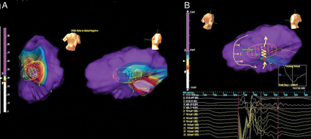
During sinus rhythm, the arrhythmia substrate was characterized by Dynamic Substrate Mapping using the EnSite System (St Jude Medical™ Inc., Milwaukee, WI, USA) with a multielectrode array inserted via the left femoral artery and advanced retrogradely into the left ventricle. Peak negative voltage values of all local virtual unipolar electrograms of the left ventricle were plotted on the previously acquired chamber geometry, to provide a static isopotential voltage map during sinus rhythm (Figure 1A). The criteria of peak negative voltage <34% of unipolar non-contact electrograms was used to define scar tissue1; a wide scar area was thus identified in the basal portion of the inferior was of the left ventricle. Sinus rhythm propagation in the left ventricle was then analysed. The impulse emerging from the bundle branches in the posterior septum reached the left ventricular apex and then the lateral wall, travelling around a region of functional block in the mid portion of the inferolateral wall; subsequently, the portion of the inferior wall between the area of scar and the area of functional block was slowly activated in postero-anterior direction (Figure 1B, Supplementary Video S1). Virtual electrograms registered a slow continuous diastolic activity in that area spanning to 200 ms after the surface QRS onset; the distal bipolar electrode of the ablation catheter (Biosense-Webster Thermocool) placed in the area corresponding to the virtual electrode 13 in Figure 1B confirmed the presence of a late potential occurring a 200 ms after the surface QRS onset and 105 ms after the surface QRS end.

(A) Dynamic substrate mapping was analysed by a non-contact EnSite system. The wide yellow circumference encircles the area with peak negative voltage <34% of unipolar non-contact electrograms; a wide scar area was thus identified in the basal portion of the inferior was of the left ventricle. (B) Sinus rhythm propagation in the left ventricle. The yellow arrows describe the impulse propagation pattern identified by non-contact mapping. The impulse, travelling around a region of functional block in the mid portion of the inferolateral wall, activated the area between the scar tissue and the zone of functional block in postero-anterior direction. The yellow zig-zag line highlights an area of slow conduction in correspondence of virtual electrograms 11–13, evident as slowing of sinus rhythm impulse progression at video propagation analysis; those electrograms registered a slow continuous diastolic activity spanning to 200 ms after the surface QRS onset; the distal bipolar electrode of the ablation catheter placed in the area corresponding to the virtual electrode 13 recorded a late potential occurring a 200 ms after the surface QRS onset.
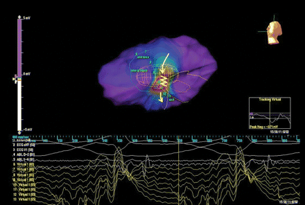
Ventricular tachycardia was then induced by programmed ventricular stimulation and interrupted by overdrive pacing; left ventricular activation during tachycardia was then analysed by non-contact mapping (Figure 2 and Supplementary Video S2). The impulse travelled in an antero-posterior direction from the site of virtual electrode 8 (entrance site), which registered a small early diastolic activity, to the site of virtual electrode 10 (central portion); in that area a slowing down of the conduction was evident and the virtual electrode registered a small mid diastolic activity 70 ms before the surface QRS onset; finally the impulse emerged at the site of virtual electrode 12 (exit), synchronous to the surface QRS onset, to activate the left ventricular mass.

Left ventricular activation during tachycardia analysed by non-contact mapping. The yellow arrows describe the direction of conducting channel activation during VT (antero-posterior direction). The yellow zig-zag line highlights an area of slow conduction in correspondence of virtual electrograms 10–11, evident as slowing of sinus rhythm impulse progression at video propagation analysis; virtual electrode 10, placed in the central portion of the conducting channel, registrated a small mid diastolic activity 70 ms before the surface QRS onset.
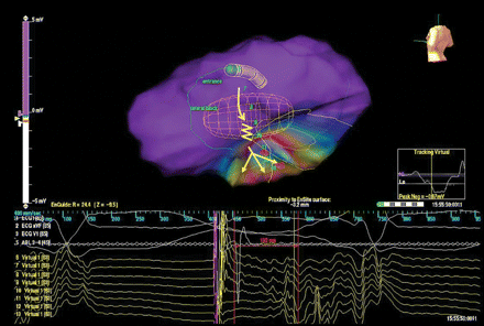
The paced QRS from the site of late activity during sinus rhythm matched the VT morphology with a long stimulus-to-QRS interval (130 ms); virtual electrograms in the area of supposed VT re-entry circuit registered a slow continuous activity between the pacing artefact and the surface QRS onset; when the impulse reached the site of virtual electrode 12, it spread out from the conducting channel to activate the left ventricle (Figure 3 and Supplementary Video S3).

Characterization of impulse propagation during pacemapping. The stimulus-to-QRS interval is long (130 ms), consistent with slow conduction. Virtual electrograms in the area of supposed VT re-entry circuit registered a slow continuous activity between the pacing artefact and the surface QRS onset; when the impulse reached the site of virtual electrode 12, it spread out from the conducting channel to activate the left ventricle.
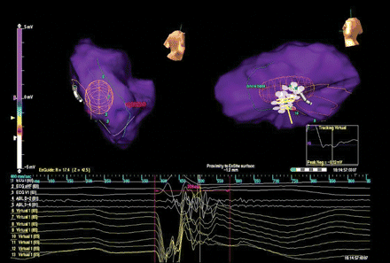
Radiofrequency ablation was performed by repeated pulses (35 W, 43 °C) to intersect the conductive channel. Programmed stimulation after the ablation was not able to induce any VT. Left ventricular endocardial activation during sinus rhythm was then analysed by non-contact mapping (Figure 4 and Supplementary Video S4). The impulse emerging from the bundle branches in the posterior septum reached the inferior wall following the same pathway used before radiofrequency ablation, but propagation failed to penetrate the conductive channel with block at the virtual electrode 11; no late potential activity could be recorded after the QRS end (the red vertical caliper highlight the time frame of 200 ms after the QRS onset, where previously a late potential was found).

Left ventricular endocardial activation during sinus rhythm after radiofrequency ablation. The impulse reached the inferior wall following the same pathway used before radiofrequency ablation and it blocked at the virtual electrode 11; no late potential activity could be recorded after the QRS end (the red vertical caliper was placed at 200 m after the QRS onset).
Discussion
Sustained monomorphic VT in patients with a previous myocardial infarction is due to re-entry mechanism in areas of slow conduction; however, the recognition of the pathogenic mechanism and the characterization of the activation pathway are usually obtained by indirect measures with entrainment mapping and pacing manoeuvres. The present is, to our knowledge, the first published in vivo direct visualization of the critical components of re-entry by non-contact mapping; VT circuit entrance, central pathway, and exit were characterized during the same beat by virtual electrodes and visualized on a three-dimensional map both during sinus rhythm, ongoing VT, and pacemapping. The analysis demonstrated an activation of the conductive channel in opposite directions during the sinus rhythm and ventricular tachycardia. In previous studies, entrainment mapping showed that late potentials were frequently recorded in sites classified as central or proximal in the re-entry circuit.2,3 Late potentials during sinus rhythm turned into mid-diastolic activity during VT; non-contact mapping allowed the ablation procedure to be performed in sinus rhythm, targeting the central pathway of the conducting channel; successful ablation was associated with disappearance of late potentials on contact mapping and to the disappearance of conduction within the channel, as assessed by non-contact mapping. This appears to be the first in vivo demonstration during sinus rhythm of arrhythmia substrate modification by radiofrequency ablation.
Disclosures
Dr Paolo Della Bella PDB is consultant for St Jude Medical and has received honoraria for lectures form Biosence Webster, St Jude Medical and Biotronik.
Supplementary material
Supplementary videos for each figure are available at Europace online.


