


Abstract
Catheter ablation of isthmus-dependent atrial flutter is technically demanding in some patients and extremely simple in others. The intervention targets a defined anatomical structure, the so-called cavotricuspid isthmus (CTI). We sought to characterize CTI anatomy in vivo in patients with difficult and simple catheter ablation of atrial flutter.
Twenty-six patients were studied. Seven patients with difficult ( n = 6) or extremely simple ( n = 1) CTI ablation procedures were retrospectively selected from our catheter ablation database. Thereafter, we prospectively studied 19 patients undergoing CTI ablation in our department. We visualized CTI anatomy by ECG- and respiration-gated free precession 1.5 T cardiac magnetic resonance imaging (MRI). Magnetic resonance imaging was analysed for systolic and diastolic CTI length, the angle between the vena cava inferior and CTI, and pouch-like recesses. These parameters were compared between patients with difficult and simple procedures, split by the median number of energy applications. Patients with difficult procedures had a longer diastolic CTI length (diastolic isthmus length 20.3 ± 1.8 mm) than those with simple procedures (diastolic isthmus length 16.6 ± 1.7 mm, all data as mean ± SEM, P < 0.05). Cavotricuspid isthmus angulation with respect to inferior vena cava was closer to 90° in patients with difficult procedures (deviation from 90°: 15 ± 2°) than those with simple procedures (deviation 23 ± 4°, P < 0.05). Systolic CTI length was not different between groups (32 ± 2 mm in both groups, P > 0.2).
Longer diastolic, but not systolic, CTI length and a rectangular angle between CTI and inferior vena cava render CTI catheter ablation difficult. Visualization of isthmus anatomy may help to guide difficult CTI ablation procedures.
Introduction
Shortly after the description of its electrophysiological mechanism macro-reentry around the tricuspid valve, 1–3 catheter ablation emerged as the treatment of choice for typical, isthmus-dependent atrial flutter. 4 , 5 The ablation procedure creates a linear scar in the myocardium of the cavotricuspid isthmus (CTI), a relatively thin muscular strand that is a critical part of the flutter re-entrant circuit. Catheter ablation in the CTI can cure 90% of the patients with isthmus-dependent atrial flutter, 6–9 and re-ablation is often successful in the remaining 10% of the patients. Larger or irrigated-tip radio frequency ablation catheters and the use of three-dimensional catheter localization systems have reduced procedure and fluoroscopy times. The use of an irrigated-tip ablation catheter has increased procedural success rate in a trial, 10 but, in general, larger tip and irrigated tip ablation catheters or the use of cryo-energy rather than radio frequency energy does not markedly improve CTI ablation success. 10–16 In contrast to the intuitive expectation of interventional electrophysiologists, the use of mapping systems did not increase CTI ablation success rates in a controlled trial. 16 These observations may be interpreted as a sign that more precise positioning of the ablation catheter or higher energy delivery cannot solve all difficulties in technically demanding CTI ablation procedures.
As isthmus ablation targets a well-defined anatomical structure, a specific anatomy of the CTI may be a cause for difficult or non-successful CTI ablation. 17–19 Evidence for such anatomical characteristics has been reported by angiographic studies, 17 , 19 , 20 multi-slice computed tomography (MSCT), 21 and one cardiac magnetic resonance imaging (MRI) study. 22 A longer CTI, usually measured during mechanical diastole, and possibly pouches in the CTI region, 19 , 22 may be related to difficult ablation procedures. Magnetic resonance imaging has the potential to visualize cardiac anatomic structures in vivo22 , 23 and may, in the future, be used to guide ablation procedures. 24 We therefore performed an MRI study of CTI anatomy prior to CTI ablation to characterize anatomic details in ‘difficult’ CTI ablations.
Methods
Patients were eligible if they underwent catheter ablation in the CTI for curative treatment of isthmus-dependent atrial flutter. The first seven patients were identified by a retrospective database search of all patients who underwent catheter ablation for atrial flutter at the Department of Cardiology of the University Hospital Münster from 1999 to 2004 (more than 200 patients). In this database, we identified six eligible consenting patients with difficult procedures, i.e. patients with either unsuccessful ablation attempts ( n = 2) or those receiving more than 15 point-by-point energy applications to achieve complete CTI block ( n = 4), and one patient with a simple procedure. All patients were contacted through telephone and asked whether they were willing to undergo MRI of the isthmus. In a second phase of the study, we prospectively included patients who underwent catheter ablation of atrial flutter in our department from April 2004 to March 2005. The study complied with the standards for research in patients as defined by the WHO and was approved by the local Ethics Committee. All patients gave written informed consent for the MRI study.
Cavotricuspid annulus ablation was performed following standard procedures from a femoral access using a biplane fluoroscopy system. Point-by-point ablation (90 s ablation duration per catheter position) was performed in a temperature-controlled mode (60°C maximal temperature), with a power setting of 70 W (50 W for 4 mm tip electrodes). Complete bidirectional CTI block was assessed at the end of the ablation procedure during pacing in the coronary sinus ostium and low lateral right atrium by a combination of changes in the right atrial activation sequence measured by a multipolar ‘Halo’ catheter, an increase in trans-isthmus conduction times, and double-potential mapping at the CTI. 25 These were measured after the last energy application and after a 30 min waiting period to assess recovery of isthmus conduction. When isthmus conduction recovered, the ablation was continued. The use of a mapping system and the choice of the ablation catheter were driven by the preference of the interventional electrophysiologist in charge of the procedure. All ablation catheters used were available in different curves as supplied by the manufacturer or were equipped with an adjustable curve size. The MRI anatomic information, which was analysed offline, was not used during ablation.
Patients were studied using a 1.5 T magnetic resonance tomography system (Philips ® Aptiva, Philips Medical Systems, Hamburg, Germany) by steady-state respiration- and ECG-gated free precession sequences, similar to published protocols for MRI-based image fusion. 26 Scout sequences were used to identify the inferior right atrium and the inferior vena cava. The CTI was visualized in the right and left anterior oblique projections, parallel and perpendicular to the orientation of the interventricular septum. The length and width of cavotricuspid isthmus were measured in diastole and systole as the linear distance between the tricuspid annulus and the end of the right atrial myocardial sleeve. Care was taken to identify the exact extensions of the right atrial myocardium in the MRI for isthmus length determination ( Figure 1 ). On the basis of the unproven hypothesis that a rectangular orientation of the CTI with respect to the most proximal part of the inferior vena cava might prevent adequate tissue contact between the catheter tip and the CTI during the ablation procedure, 19 the angle between the inferior vena cava and the CTI was estimated by the angle between two tangential lines placed parallel to the CTI floor and parallel to the adjacent wall of the inferior vena cava ( Figure 1 ). All MRI analyses were pre-defined and performed by two observers (P.K. and D.M.) blinded to the study group. The complete data set was analysed twice. The first analysis was used to train the analysers. After a waiting period of 6 months, all MRI images were re-analysed by the same observers. When a discrepancy between the initial analysis and the second analysis was detected, the MRI images were jointly analysed for a third time by the two observers to resolve inconsistencies.
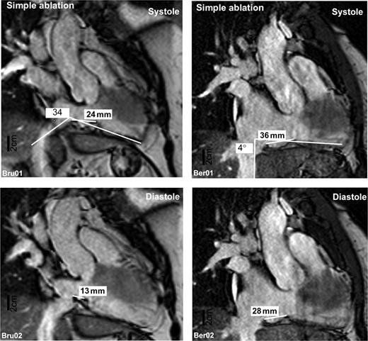
Two representative magnetic resonance images taken from a patient with a simple (left panel) and difficult (right panel) CTI ablation procedure. Images depict an approximate equivalent of an approximate 30° RAO projection adjusted to give a perspective view perpendicular to the isthmus length. Images taken during mechanical systole (upper panels) and diastole (lower panels) are shown.
Patients were divided into two groups based on the number of point-by-point ablation sites required to achieve complete bidirectional isthmus block (difficult procedures: patients with higher-than-median ablation sites, unsuccessful ablation, or one patient in whom two different energy sources were used to achieve CTI block and simple procedures: patients with lower-than-median ablation sites).
Results
Clinical characteristics of the patients are given in Table 1 . Blood pressure was not different between patient groups (simple procedures: 129 ± 3 mmHg, difficult procedures: 118 ± 4 mmHg). Coronary artery disease was present in one patient with a simple procedure and in four patients with a difficult procedure ( P = ns). Radio frequency ablation was used in 21 patients (10 patients with 8 mm tip catheters and three patients with cooled-tip catheters) and cryo-ablation in six patients. In one patient, both a 4 mm tip radio frequency ablation catheter and subsequently a cryo-ablation catheter were used. Mapping systems and non-fluoroscopic catheter localization systems (one using CARTO ® , 10 using LocaLisa ® , and two using NavX ® ) were used in 13 patients to guide the procedure.The mean procedure duration was 195 ± 19 min, and the mean fluoroscopy time was 29 ± 4 min. Usually, fluoroscopy was used to monitor catheter stability during energy application. The clinical and procedural characteristics were not different between the patient groups with the exception of number of energy applications, fluoroscopy duration, and procedure duration, which were longer in patients with difficult procedures ( Table 1 ).
Clinical and procedural data of the study patients
| Patient no. | His # | Sex | Age (years) | Pouches | Procedural success | Number of energy applications | Energy and catheter type | Procedure time (min) | Radiation time (min) | Mapping system |
|---|---|---|---|---|---|---|---|---|---|---|
| Simple procedures | ||||||||||
| 1 | 82441 | F | 52 | No | Yes | 7 | RF 8 mm | 135 | 21.1 | LocaLisa |
| 4 | 81892 | F | 69 | y (8 mm) | Yes | 6 | RF 4 mm | 120 | 1.5 | — |
| 5 | 19674 | M | 64 | No | Yes | 8 | RF 8 mm | 135 | 21.3 | — |
| 6 | 81804 | M | 65 | y (4 mm) | Yes | 8 | Cryo | 210 | 31.2 | LocaLisa |
| 8 | 82423 | M | 53 | No | Yes | 8 | RF 4 mm | 80 | 12.9 | LocaLisa |
| 11 | 82369 | M | 64 | No | Yes | 9 | RF 4 mm | 180 | 23.6 | LocaLisa |
| 12 | 39344 | F | 72 | No | Yes | 3 | Cryo | 120 | 15.1 | LocaLisa |
| 15 | 81746 | F | 32 | No | Yes | 8 | RF 4 mm | 170 | 45.4 | NavX |
| 17 | 81756 | M | 71 | No | Yes | 2 | RF 4 mm | 105 | 13.1 | LocaLisa |
| 18 | 78841 | M | 64 | y (3 mm) | Yes | 8 | RF 8 mm | 90 | 50.7 | — |
| 19 | 81703 | F | 54 | No | Yes | 8 | Cryo | 135 | 15.9 | LocaLisa |
| Mean±SD | 6 male | 60 ± 11 | 7 ± 2* | 135 ± 37* | 23 ± 14* | 8/11 | ||||
| Median (10) | 81935 | M | 67 | y (3 mm) | Yes | 10 | Cryo | 150 | 14 | LocaLisa |
| Difficult procedures | ||||||||||
| 2 | 80421 | F | 60 | No | Modified | 41 | RF 8 mm | 396 | 57 | CARTO |
| 3 | 82184 | M | 56 | No | Yes | 18 | RFC 8 mm | 195 | 35.9 | NavX |
| 7 | 81720 | M | 50 | No | Yes | 14 | Cryo | 220 | 57.1 | LocaLisa |
| 9 | 79108 | F | 67 | No | Yes | 30 | RF 8 mm | 439 | 67.55 | — |
| 13 | 82416 | F | 70 | No | No | 12 | Cryo | 180 | 20 | LocaLisa |
| 14 | 79823 | M | 46 | No | Yes | 23 | RF 8 mm | 150 | 30.3 | — |
| 16 | 81784 | M | 65 | No | Yes | 13 | RF 8 mm | — | — | — |
| 20 | 82074 | M | 53 | No | Yes | 15 | RFC 4 mm | — | — | — |
| 21 | 79024 | M | 66 | y (2 mm) | No | 15 | RF 4 mm | 255 | 40.3 | — |
| 22 | 44108 | M | 68 | y (2 mm) | Yes | 38 | RF 8 mm | 200 | 12.9 | — |
| 23 | 44085 | M | 58 | y (3 mm) | Yes | 12 | RF 4 mm | 150 | 2.5 | — |
| 24 | 82197 | F | 61 | No | Yes | 12 | RF 8 mm | — | — | – |
| Mean±SD | 8 male | 60 ± 7 | 20 ± 10 | 243 ± 99 | 32 ± 22 | 4/12 | ||||
RF, radio frequency; RFC, radio frequency with cooled (irrigated) catheter tip; Cryo, cryo-ablation; His, unique ablation procedure identifier used for pseudonymization of the data. Localisa ® , NavX ® , and CARTO indicate mapping trademarked systems. Bold values indicate mean of groups±standard deviation (SD).
*Significant differences between groups.
Isthmus MRI could be analysed in 24 of 26 patients ( Figure 1 ). The myocardium usually extended from the tricuspid valve to the Eustachian ridge, but not beyond it. Difficult procedures were associated with a longer diastolic CTI (20.3 ± 1.8 mm, range 7–28, Figure 2 A ) than simple procedures (CTI length 16.6 ± 1.7 mm, range 9–25, P < 0.05). The angle between inferior vena cava and right atrial floor deviated less from 90° in patients with difficult procedures (15 ± 2°, range 3–30, Figure 2 B ) than in those with simple procedures (23 ± 4°, range 7–40, P < 0.05). Differences in CTI angulation were caused by either angulation of the proximal part of the inferior vena cava and/or angulation of the CTI within the thorax. Systolic CTI length was markedly shorter than diastolic CTI length in all patients (mean difference 13 ± 1 mm, or 72% of diastolic isthmus length, range 6–25), indicating movement of the CTI. The range of isthmus movement (systolic minus diastolic CTI length) was not different between the groups (simple procedures 15 ± 2 mm, range 8–25 and difficult procedures 12 ± 1 mm, range 6–20). Systolic CTI length was also not different between groups (simple procedures 32 ± 2 mm, range 24–46 and difficult procedures 32 ± 2 mm, range 17–42, P > 0.2). Three patients with incomplete CTI block after the ablation procedure (unsuccessful procedure) also had a long diastolic CTI (22 ± 2 mm, range 19–28) and a rectangular CTI orientation (17 ± 6° angle deviation, range 8–30).
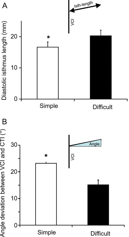
( A ) Mean diastolic isthmus length in patients with simple (open column) and difficult (filled column) ablation procedures. ( B ) Mean deviation from 90° of the angle between inferior vena cava and isthmus for simple (open columns) and difficult (filled columns) procedures. All values shown as mean and SEM.
Pouch-like recesses in the isthmus have been suspected to render CTI ablation difficult. 17 Usually, the curve of the endocardial surface of the CTI was smooth. Pouch-like recesses were found in three patients with difficult procedures in this study and in three patients with simple procedures ( P = ns). Pouches were 3–8 mm deep. The deepest pouch was found in a patient with a simple procedure. Although not part of the pre-specified analyses, we observed that the diastolic movement of the CTI amplified pouch formation during diastole. In extreme cases, the pouch even ‘closed’ to form a secluded area in the CTI by intermittent contact between the Eustachian ridge and the tricuspid annulus. These phenomena were only occasionally observed and not different between study groups.
Discussion
Main findings
Cardiac MRI can non-invasively visualize CTI anatomy in vivo . We identified several anatomic characteristics associated with difficult CTI ablation procedures:
An angulation of the CTI and the inferior vena cava close to 90° render ablation difficult. This finding suggests that catheter–tissue contact may be difficult in such situations.
The CTI is a moving target that alters its length by 30–50% during the cardiac cycle.
A long diastolic CTI length is associated with difficult ablation procedures. This finding is consistent with prior publications. The (longer) systolic isthmus length was not different between patient groups in this study.
According to MRI criteria, the right atrial myocardium extends approximately to the Eustachian valve, but not further into the vena cava. This relates well to the observation of complete CTI block prior to the ablation of an angiographically complete CTI line. 19 Right atrial angiography may slightly overestimate CTI length.
Magnetic resonance imaging of the cavotricuspid isthmus
Magnetic resonance imaging was feasible using a clinically available 1.5 T MRI system in almost all (92%) study patients. The procedure is non-invasive, was well tolerated, and, in contrast to angiography 19 , 20 or contrast-enhanced computed tomography, 21 does not require exposure to ionizing radiation or potentially nephrotoxic contrast media (∼30–50 mL for angiography and ∼100 mL for MSCT 19–21 ). The technique requires validation in larger patient cohorts and in clinical routine, but the integration of MRI into catheter localization and mapping systems 26 , 27 opens the perspective to use real pre-procedural anatomic information to guide CTI ablation in the near future, e.g. for repeat ablations.
Anatomical characteristics of the cavotricuspid isthmus in difficult procedures
Isthmus length and angulation could be readily measured in the study population ( Figure 1 ). Diastolic isthmus length was within the range of published measurements by other techniques. 19–21 Interestingly, the systolic (longer) isthmus length did not differ between simple and difficult procedures in this study. Prior publications do not specifically mention the timing of the measurement or only reported measurements for diastolic isthmus length. 17 , 19 , 20 As the catheter was usually kept stable during energy application in this study (in concordance with Da Costa et al.17 but in contrast to Heidbuchel et al . 19 ), this implies that the myocardium under the catheter will move during energy delivery. Our data can be interpreted as a sign that diastolic energy delivery may be more relevant for CTI ablation.
Magnetic resonance imaging allows to delineate CTI extension based on the limits of atrial myocardium in addition to delineation based on the endocardial shape, albeit within the limitations of the spatial resolution of a 1.5 T system. In some patients, we found that the atrial myocardial layer ended before the Eustachian ridge, resulting in a shorter length of the isthmus when measured as the length of atrial myocardium. This may explain that the isthmus lengths measured in this study are slightly shorter than in angiographic studies, which used endocardial border detection (and usually the Eustachian ridge) to delineate the isthmus limit. 19 , 20 Interestingly, one study reported that complete isthmus block occurred before ablation along the entire angiographically determined isthmus length, 19 suggestive of an overestimation of isthmus length by angiography, and consistent with the CTI length measurements in this study.
Prior angiographic studies suggested that pouch-like recesses within the isthmus were associated with difficult procedures, 17 , 19 , 22 although this was not quantified. We could not confirm this suggestion in our study (three patients with pouches in each patient group, Table 1 ). The pouch depth was also not different between patients with simple and difficult procedures. This difference between our study and prior reports may have several reasons: our patient population, albeit not homogeneously, was enriched with patients who had difficult ablation procedures ( n = 6 of the retrospective part of our cohort). Nonetheless, pouches were relatively rare in our study group, suggesting that other factors rendered ablation difficult. Furthermore, we cannot exclude that differences in the MRI technology influenced detection of pouch-like recesses. Occasionally, the cine-mode MRI gave the impression that pouches were ‘closed’ during diastole. This preliminary observation may warrant further evaluation.
Angulation of the isthmus with respect to the inferior vena cava
A rectangular orientation of the CTI with respect to the inferior vena cava was associated with difficult procedures in this study. Only one angiographic study reported that measurements of CTI angulation were performed, 19 but there are no results for simple and difficult procedures in that paper. This is the first study that identified a rectangular orientation of the CTI with respect to the proximal part of the inferior vena cava as a factor that renders isthmus ablation difficult. Hypothetically, a rectangular angle between the inferior vena cava and the isthmus area could hinder adequate contact of the tip of the steerable catheter to parts of the myocardial sleeves within the isthmus, especially in the caval part of the CTI. It is also conceivable that a rectangular position of the CTI could facilitate intermittent loss of contact of the catheter tip to the CTI during the cardiac cycle. These factors could impede completion of the ablation line. Ideally, this hypothesis could be tested in a system that allows MRI during the ablation procedure, whereas the catheter is in contact with the CTI. 28
Limitations
This study is hypothesis-generating, and larger, prospective, multi-centre series are required to confirm the observations reported and to determine the clinical usefulness of CTI visualization prior to catheter ablation. The patient population is heterogeneous, partially prospectively and partially retrospectively selected, and relatively small. The majority of patients in this study underwent MRI during sinus rhythm. As MRI, comparable with other ‘signal-averaged’ imaging modalities such as computed tomography or positron emission tomography, relies on ECG and respiration triggering, MRI during atrial fibrillation or flutter may be more difficult to interpret. The present study used a 1.5 T MRI system available in clinical routine at many centres. The spatial resolution of this system has prevented reliable measurements of myocardial thickness in this study, and thin or isolated myocardial sleeves may extend beyond the myocardial boundaries identified in this study (i.e. beyond the Eustachian ridge). Finally, the MRI system and sequences used in this study did not allow to delineate small coronary vessels that could at times be associated with failure of isthmus ablation 18 and may have limited our ability to identify pouch-like recesses. Future studies, possibly using MRI systems with higher spatial resolution, may help better delineate these details.
Conflict of interest: C.K. and S.P. have received travel grants and honoraria from Siemens Medical Systems. P.S. served on advisory boards for Siemens. P.K. has received honoraria or travel grants from or served on advisory boards for Medtronic, St. Jude Medical, Siemens, and various pharmaceutical companies. P.S. and P.K. have been involved in research on image integration which was partially supported by TomTec Imaging systems. D.M. has received honoraria from Philips Medical Systems and from Siemens.
Funding
This study is supported by the German Federal Ministry of Education and Research (BMBF) through the Atrial Fibrillation Competence NETwork (AFNET, projects B7, B11 and C1, grant no. 01Gi0204).
