


Abstract
Catheter ablation is an effective treatment for symptomatic atrial fibrillation. A thorough understanding of the left atrium anatomy and its adjacent structures is critical for the success of the procedure and for avoiding complications. Pre-procedural imaging aims at determining left atrial size, anatomy, and function and is also used to rule out an atrial thrombus. During the procedure, while fluoroscopy remains the gold standard imaging modality for guiding transseptal catheterization and catheter ablation, numerous other imaging modalities have been developed to improve 3D navigation and ablation. Finally, post-operative imaging intends to monitor heart function and to search for potential complications like pulmonary vein stenosis or the rare but dramatic atrio-oesophageal fistula. This review discusses the relative merits of all imaging modalities available in the context of catheter ablation of atrial fibrillation.
Introduction
Catheter ablation is an effective treatment for symptomatic paroxysmal and persistent atrial fibrillation (AF). 1–4 Multiple ablation strategies have been reported based on an electrogram analysis, 5 , 6 anatomical targets, 2 or both. 5 For all of these approaches, a thorough understanding of the anatomy of the left atrium (LA) and adjacent structures is critical to achieving the success of catheter ablation and avoiding complications. This review treats the relative merits of the numerous imaging modalities available and their respective use in planning and performing catheter ablation. It also discusses the role of different imaging tools during follow-up of patients.
Pre-procedural imaging
Left atrial size, anatomy, and function
A transthoracic echocardiogram (TTE) has obviously to be performed in all patients with AF prior to the consideration of ablation. A TTE is mandatory to rule out any other cardiac pathology that may have led to AF, such as mitral valve disease, left ventricular dysfunction, and hypertensive heart disease. In addition, LA dimensions can be accurately assessed, giving an estimate of the duration of AF and being independently predictive of the procedural termination of AF with catheter ablation. 7
Determination of gross cardiac anatomy and landmarks
Pulmonary vein (PV) isolation is the cornerstone of all ablation strategies for both paroxysmal and persistent AF, and therefore an accurate knowledge of an individual’s PV anatomy is useful prior to the procedure. The majority of patients have four PVs, two superior and two inferior with independent ostia draining separately into the LA. A number of variations have been described in the literature, the commonest of which are: left common ostium (up to 83% of patients), right common ostium (up to 40%), and a separate origin for the right middle PV (up to 27% of patients). 8 Although prior knowledge of the diameter of the PVs is useful in the sizing of circular mapping catheters, it is essential if balloon-based ablation catheters are to be used, as a close approximation of the balloon to the PV ostia is required for successful isolation. 9
Although transoesophageal echocardiography (TOE) can provide an assessment of PV diameter, the most accurate measure is provided by computed tomography (CT) scanning or magnetic resonance imaging (MRI). 10 Using these scanning modalities, the oval nature of the left-sided PVs is more readily appreciated, with a superior–inferior diameter larger than the anterior–posterior dimension, in comparison with the more circular nature of the right-sided PVs. Additionally, CT or MRI can provide useful information about other atrial or venous structures targeted during the ablation. It has been shown that the septal anatomy is accurately visualized on CT, 11 which may be helpful during the procedure, however, TOE is the most accurate modality to detect the presence of a patent foramen ovale. 12
Detection of atrial thrombus
Screening for the presence of an atrial thrombus is mandatory prior to AF ablation for patients at risk, as catheter manipulation could dislodge a thrombus with the potential for embolic complications. Current guidelines suggest that the management of patients with AF at the time of the procedure should be the same as that for a cardioversion. 13 They should have TOE performed within 48 h of the procedure regardless of whether they have been anticoagulated with warfarin or not prior to cardioversion. Although a CT scan (especially 64-slice) can rule out a thrombus with a high negative predictive value, 14 the differentiation between pectinate muscle, blood stasis (smoke), and thrombus within the LA appendage is challenging. For low-risk lone paroxysmal AF with prior anticoagulation, there is some uncertainty about the utility of performing routine thrombus detection. 13 In this case, TTE can be used to risk-stratify patients before performing TOE with a very high negative predictive value. 15
Procedural imaging
Trans-septal catheterization
The majority of the population does not have a patent foramen ovale and, thus, requires a trans-septal puncture for access into the LA. Using the standard Brockenbrough approach (with fluoroscopy only), a ‘jump’ is seen when pulling the trans-septal sheath down the septum, indicating the position of the foramen ovale. 16 The needle position in relation to the septum can be checked in relation to catheters marking the His and CS, using orthogonal planes. Injection of contrast onto the septum helps in assessing the exact location of the needle before advancing the dilator and the sheath. This method provides sufficient information to perform a safe trans-septal puncture in the vast majority of cases, but variations in the septal anatomy or adjacent structures may increase the risk of complications. 17 Transoesophageal echocardiography can help to localize the septum, with tenting seen when the needle and sheath are pushed onto the foramen. The problem with using TOE is that the patient is in a prone position, making airway management difficult, often with the requirement of general anaesthesia. To overcome this problem, intra-cardiac echocardiography (ICE) is routinely used in some centres to facilitate an accurate definition of the region. 18
Catheter ablation
Pulmonary vein isolation
Isolation of the PVs has shifted to proximal ablations, either ostial or ‘antral’, from earlier more distal ablations that led to an unacceptable rate of PV stenosis. Therefore, delineation of the veno-atrial junction is essential. Using catheter manipulation alone, the inferior portion of the PV can be readily determined by advancing the ablation catheter inside the PV with a downward deflection of the tip, and then dragging back during fluoroscopic monitoring to register the drop off to the LA. Pulmonary vein angiography in orthogonal views gives supplementary information and is easily performed. A CT or MRI scan, merged with a three-dimensional reconstruction map or overlaid on live fluoroscopic images, 19 offers even more detailed anatomy. Intra-cardiac echocardiography provides additional Doppler colour flow imaging that can be used for monitoring of real-time PV ostial narrowing, estimation of the tissue contact, and detection of thrombus, coagulum, or micro-bubbles. 20–24
Atrial ablation
In persistent AF, it has emerged that the atrial substrate maintaining AF needs to be modified. Electrogram-based ablation and linear ablation can be facilitated by ICE, CT, and MRI techniques, which can be integrated with three-dimensional mapping systems 25–27 ( Figures 1 and 2 ) or overlaid on real-time fluoroscopic images. 19 , 28 Merging of three-dimensional images using CT, MRI, or ICE with three-dimensional mapping systems offers precise details of anatomy with real-time positioning of catheters during AF ablation ( Figures 1 and 2 ). This has been shown to improve the success of ablation, decrease the occurrence of PV stenosis, and reduce fluoroscopic time. 29 Rotational angiography has also shown promising results and can be performed at the time of the ablation procedure. 30 , 31
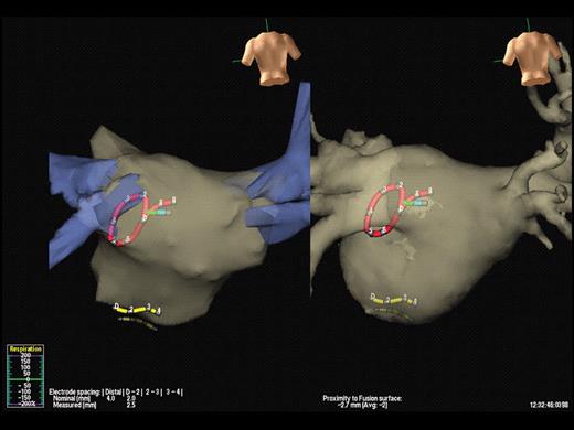
Integration of computed tomography with electro-anatomic mapping. In this example, a pre-procedural computed tomography scan of the left atrium is merged with a non-contact mapping system, NavX™. The positions of the circular mapping catheter, the coronary sinus catheter, and the ablation catheter can be seen (red, yellow, and green, respectively). The left-hand panel shows the images prior to merging, using fixed reference points and the right-hand panel shows the final result.
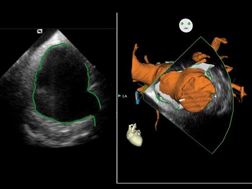
Using this new system (CARTO SOUND™), real-time images using intra-cardiac echocardiography can be integrated into the electro-anatomical mapping system, CARTO™. The left-hand panel shows the intra-cardiac echocardiography image of the left atrium, with manual delineation of the atrial walls and pulmonary venous ostia, whereas the right-hand panel demonstrates the three-dimensional representation of the left atrium and attached structures taken from the intra-cardiac echocardiography image.
We have evaluated the feasibility of an advanced overlay system between CT anatomical information and two-dimensional fluoroscopy. This system allows viewing the inside of the CT volume (‘endoscopic view’), correcting the three-dimensional CT image dimensions in relation to the X-ray cone beam of the C-arm system, and tagging catheter positions on the CT volume ( Figure 3 ). In addition to fluoroscopic time reduction, 19 this system facilitates detailed pre-procedural assessment of cardiac anatomy, catheter manipulation and subsequent ablation, as well as determination of the true PV ostia and anatomical variations. This has also been demonstrated to facilitate a safe trans-septal puncture by the visualization of the fossa ovalis. 19
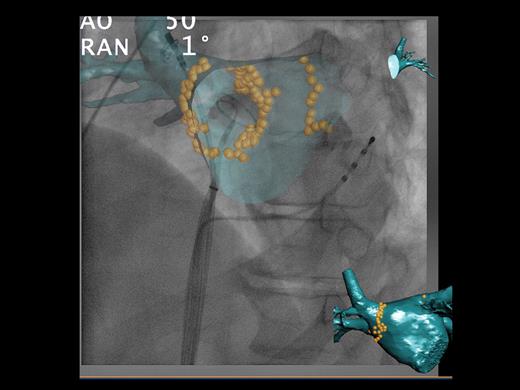
Phillips computed tomography overlay system™. Using the system, a pre-procedural computed tomography scan of the left atrium is overlaid onto live fluoroscopic images. In this example, an endoscopic view has been chosen to show the internal surface of the left atrium. The ablation points have been tagged with yellow orbs. The coronary sinus catheter can be seen, the circular mapping catheter has been placed in the right inferior pulmonary vein, and the ablation catheter is within the right superior pulmonary vein. In this system, the rotation of the computed tomography overlay is parallel to that of the C-arm, allowing accurate catheter positioning, in any view.
Oesophagus
The rate of oesophageal injury (oesophagitis, necrosis, or ulcer) as visualized by endoscopy has been reported in up to 35% of patients. 32 Oesophageal injury is believed to be due to thermal injury as a consequence of its close anatomic relationship to the posterior LA. Barium administration, 33 ICE, 34 and tagging techniques guided by electro-anatomical and imaging modalities 35 , 36 can be used to assess the position of the oesophagus; however, all are limited by the mobility of this structure and by a low positive predictive value. In contrast, the risk of this complication may be considerably lowered (and virtually eliminated) by reducing the power (<25 W) and duration (<30 s) at each ablation site and by monitoring the patient’s pain during ablation. 34
Lesion assessment
Lesion assessment can be indirectly evaluated at the time of ablation by looking at the electrogram amplitude, impedance, and temperature at the tip of the ablation catheter. Intra-cardiac echocardiography offers a direct vision of the contact between the catheter tip and the atrial surface. 21 Other tools with robotic systems indirectly assess contact by measuring force applied on the surface of the heart. 37 One study evaluated the use of high spatial resolution MRI following ablation to assess for gaps. 38 With delayed enhancement, it was possible to visualize scars created by ablation and to see areas around PVs where the tissue was not altered. 38 Present imaging modalities can identify areas of anatomical scar but the resolution is not adequate enough to identify islands of electrically intact tissue within the scar areas. Therefore, the only method to assess the electrical completeness of linear lesions is by using mapping catheters and relevant pacing manoeuvres.
Post-operative imaging
Remodelling after AF ablation
Restoration of sinus rhythm by catheter ablation has been shown to improve LA and left ventricular function. Acutely, restoration of sinus rhythm can be followed by transient atrial dysfunction or ‘stunning’ with transient decrease in the LA appendage emptying velocity and emptying fraction by TOE. 39 This can increase the risk of stasis and new thrombus formation in the LA appendage and for this reason, anticoagulation should be started immediately following the procedure. However, after a few weeks, LA function and volume as well as LV systolic and diastolic function improve dramatically if sinus rhythm is maintained. 40 , 41 This is particularly striking in patients with congestive heart failure, with the greatest improvement noted within the first 3 months of the ablation procedure. 42 Interestingly, LA mechanical function persists despite extensive LA scarring following AF ablation, with evidence of late mitral diastolic flow on Doppler studies corresponding to active atrial emptying. 41
Assessment of complications
Early complications
Pericardial effusion can occur during catheter ablation, but may manifest several hours following the procedure and for this reason, patients should have a repeat TTE prior to discharge following the procedure, especially if there is haemodynamic compromise. Transthoracic echocardiogram is the study of choice as it is easily and rapidly performed and invaluable in the follow-up of the effusion.
Pulmonary vein stenosis
Pulmonary vein stenosis decreases in frequency following AF catheter ablation because of more proximal PV isolation. 42 There is discordant data in the literature concerning the incidence of iatrogenic PV stenosis after AF ablation, varying from 0 to 42%. 43–45 This can be explained by the lack of a standard definition of PV stenosis, the different imaging modalities used to diagnose PV stenosis, and the inhomogeneity in follow-up. Pulmonary vein stenosis tends to occur immediately after the ablation. 44 , 45 In most patients, there will be a progressive narrowing of the stenosis, although acute PV stenosis can rarely heal spontaneously. Of note, some patients without acute/peri-procedural narrowing will still have significant PV stenosis revealed by later imaging. Computed tomography and MR angiography are considered the gold standards for the detection of PV stenosis. Although pulmonary angiography is accurate, due to its invasive nature and the need for multiple scans over time, this is not the preferred option. Functional testing with single photon emission computed tomography and magnetic resonance perfusion scanning have also been studied 42 , 44 and were able to detect decreased perfusion in patients with PV stenosis which later improved following restoration of flow. 42 , 44
Oesophageal injury
The dramatic atrio-oesophageal fistula is reported in 0.1–1% of cases but is fatal in 80%. 46 If such a diagnosis is suspected, TOE and oesophagoscopy are to be avoided. These increase the risk of further oesophageal injury and air emboli. The examination of choice is CT with water soluble contrast, which allows the fistula to be visualized. Magnetic resonance imaging can also be used in this situation.
Conclusion
While TTE and fluoroscopy are mandatory for all patients in the context of AF ablation, other imaging modalities are dependant on the practice and experience of each centre. There must be a balance between reduction in irradiation and procedural duration, improvement in catheter manipulation, financial considerations, and the side effects of each imaging procedure as it may result in increased contrast use, increased irradiation, and a false impression of safety. One must keep in mind that the number one imaging modality during AF catheter ablation remains the display of electrograms.
Conflict of interest: P.J., M.H. and M.H. have served on the advisory board of, and received lecture fees from Biosense-Webster. S.K. has received lecture fees from Biosense-Webster. P.J. and S.K. have received lecture fees from Philips Medical Systems. S.K. has received lecture fees from St Jude Medical.
Funding
S.K. is supported by the Belgian Foundation for Cardiac Surgery. M.D.O. is supported by the British Heart Foundation.
