


Abstract
Advanced intra-procedural imaging techniques have been integral to technical and procedural success transcatheter devices. A novel leaflet approximation therapy, the PASCAL Transcatheter Valve Repair System (Edwards Lifesciences, Irvine, CA, USA) has demonstrated high procedural success, acceptable safety, and significant clinical improvement in patients with severe mitral and tricuspid regurgitation and has CE mark approval in Europe with pivotal trials underway in the USA. This review outlines the pre-procedural imaging views and advanced transoesophageal imaging protocols both mitral and tricuspid valve device implantation.
Introduction
Despite the poor outcomes associated with untreated significant mitral (MR) and tricuspid regurgitation (TR), surgical interventions to treat these valvular conditions have been underutilized1,2 resulting in a large population of symptomatic patients with limited options. Recent trials have shown significant benefits with transcatheter edge-to-edge repair (TEER) device for primary3 and secondary4 MR. A novel leaflet approximation therapy, the PASCAL Transcatheter Mitral Valve Repair (TMVr) System (Edwards Lifesciences, Irvine, CA, USA) has demonstrated high procedural success, acceptable safety, and significant clinical improvement in compassionate use patients.5 The 1-year results of the PASCAL TrAnScatheter Mitral Valve RePair System (CLASP) early feasibility study (NCT03170349) showed low complication rates and high survival, sustained MR reduction, and significant improvements in functional status and quality of life.6
The compassionate use of the PASCAL Transcatheter Tricuspid Valve Repair (TTVr) device for TR reported a 30-day mortality of 7.1%, acceptable safety metrics7 with 85% achieving mild or moderate TR following device placement (P < 0.001). The single-arm, multicentre, prospective CLASP TR Early Feasibility Study (NCT03745313) recently reported its 30 days results showing a favourable safety profile with low major adverse events rate and no mortality at 30 days. The PASCAL TTVr device received CE mark in May 2020.
Although multiple prior imaging reviews have been published outlining the intra-procedural imaging for TEER guidance,8,9 there are differences in the procedural steps for the PASCAL device. Both the pivotal CLASP IID/IIF trial (NCT03706833) for degenerative and functional MR as well as the pivotal CLASP II TR trial (NCT04087145) for TR, are currently enrolling, and require pre-procedural transoesophageal echocardiography (TEE) for determination of valve morphology, severity of disease and adequacy of required intra-procedural imaging. This review will outline the standard TEE views for both pre-procedural and intra-procedural imaging and highlight the procedural differences with TEER. Patients whose images were used in this review were participants of the CLASP and CLASP TR studies. The studies were approved by the Columbia University Institutional Review Board.
PASCAL repair system
Features unique to the PASCAL repair system including a central spacer and adjacent paddles and clasps that attach the implant to the native leaflets to reduce regurgitation and is available in two sizes (Figure 1). The narrower width of the ACE device has been favoured for manoeuvring through dense chordal structures. The spacer and paddles are a single structure of interwoven nitinol wires acting as a flexible frame to capture the leaflets and minimize leaflet stress.10,11 The nitinol clasps have a horizontal row of four retention elements near the top of the clasps intended to run parallel to the mitral leaflet collagen fibres, potentially reducing leaflet injury. The clasps can be actuated simultaneously or independently when grasping the leaflets allowing for optimization of leaflet insertion. An elongation mechanism allows positioning and repositioning with less risk of chordal entrapment.
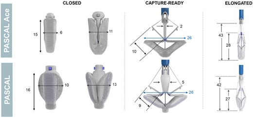
The PASCAL Repair System. There are features unique to the PASCAL repair system including a central spacer and adjacent paddles and clasps that attach the implant to the native leaflets to reduce regurgitation. (Note: all dimensions are in millimeters).
Transoesophageal echocardiography imaging protocols
The PASCAL repair system is implanted under TEE and fluoroscopic guidance. The imaging protocols will be divided into the following sections: (i) standard views for pre-procedural planning, (ii) pre-procedural assessment of valve morphology and function, and (iii) guidance of the procedure. Each step will be divided into mitral-specific and tricuspid-specific imaging protocols.
Standard views for pre-procedural planning
Appropriate 2D and 3D imaging with Doppler should be performed prior to and following device placement to quantify valve function. Figure 2 shows the primary imaging levels and views required for assessment of MV and TV morphology and function utilizing the probe manipulations described in prior guidelines.12 The standard four levels of imaging include: high oesophageal (HE), mid oesophageal (ME), shallow transgastric (TG), and deep transgastric (DT). For the MV and TV, the HE level is rarely used. A new distal oesophageal (DE) imaging level has been added for imaging the TV.
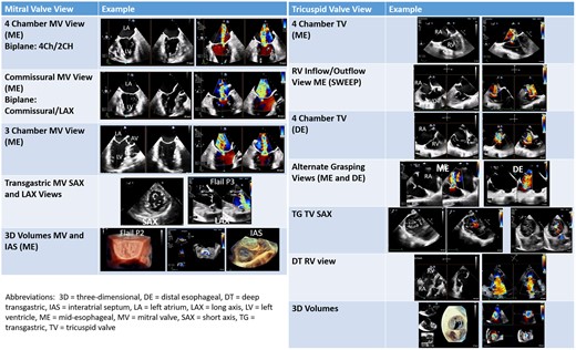
Primary imaging views for the mitral and tricuspid valve. The primary imaging views used for pre-procedural planning and intra-procedural guidance are shown in this figure.
Because of anatomic variability not only of the cardiac structures themselves but also the relationship of the oesophagus to the heart structures, it is important to confirm complex valvular anatomy using 3D imaging.13 The ‘surgeon’s view’ imaging display for the en face view of the MV (Figure 3A) is advocated14 which requires varying degrees of Z-plane rotation depending on the acquisition image. The 3D en face MV view acquired from the 2D commissural view will image the posterior leaflet in the near field prior to Z-plane rotation (Figure 3B); some imagers/interventionalists prefer this image which minimizes image manipulation and mimics the 2D image by positioning the lateral commissure on the right and the medial commissure on the left side of the screen. Similarly the 3D en face TV view acquired from the 2D commissural view (and without Z-rotation), positions the interventricular septum on the right side of the screen, the aorta at 5 o’clock and the posterior leaflet in the near field (Figure 3C), an orientation similar to the TG SAX view.15 Creating multi-beat colour Doppler 3D volumes without splice artefacts for measurement of systolic regurgitant jet vena contract area (VCA) is possible even with irregular rhythms (Figure 3D).
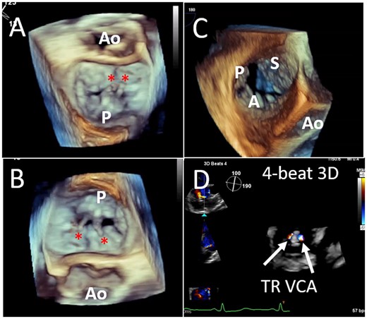
Three-dimensional imaging of the mitral and tricuspid valves. Standardized imaging display for the en face view of the MV with both lateral and Z-plane rotation (A) and without Z-plane rotation (B); ruptured P2 chordae are seen (asterisk). A real-time 3D en-face view of the TV without Z-plane rotation, results in leaflet orientation similar to the transgastric view (C). Creating multi-beat colour Doppler 3D volumes of the systolic regurgitant jet, allows planimetry of the MR VCA post-device (D). MR, mitral regurgitation; MV, mitral valve; TV, tricuspid valve; VCA, vena contracta area.
Mitral valve
Because of the relative positions of the oesophagus and left atrium, aligning the annulus perpendicular to the insonation beam may require right flexion in addition to retroflexion. Aligning the annulus perpendicular to the insonation beam has the following advantages: (i) both biplane images are typically perpendicular to leaflet coaptation (which allows simultaneous imaging of the clasp arms); (ii) orientation of the real-time multi-planar 3D image or 3D en face view is easier; and (iii) the trajectory of the system is more accurately assessed.
The ME MV commissural view at a transducer angle between 50° and 70°, is often seen as the ‘home’ view for the PASCAL system (Figures 2 and 4). Using biplane imaging, the orthogonal imaging plane can be positioned across the commissural line, and thus sweep from the lateral commissure of A1/P1 (right sector, Figure 5A) to the midline (A2/P2, Figure 4B), and finally the medial commissure (A3-P3, Figure 4C), without and with colour flow Doppler. TG views may be useful not only for Doppler of the aortic valve (i.e. to calculate forward stroke volume) but also to evaluate the MV (Figure 2). Although short-axis views of the MV are rarely used given the use of ME 3D imaging, occasionally acoustic shadowing prevents an adequate assessment of the tissue bridge and the TG short-axis view can be helpful. In addition, commissural regurgitant jets may be aligned with the insonation beam only from the TG views (Figure 2).
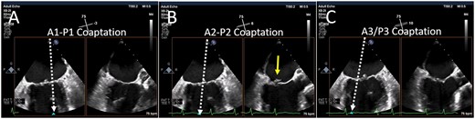
Biplane imaging from the MV commissural view. Using simultaneous biplane imaging with the mid-oesophageal MV commissural view as the primary image, a sweep of the entire commissure can be performed. (A) The position of the orthogonal image (white arrow) at the lateral commissure (A1-P1 scallops). (B) The position of the orthogonal image at the midline (A2-P2 scallops) where a small flail posterior scallop is imaged (yellow arrow). (C) The position of the orthogonal image at the medial commissure (A3-P3 scallops). MV, mitral valve.
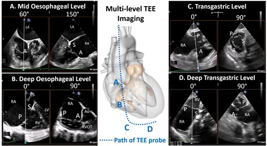
Four levels of imaging for the tricuspid valve. The path of the oesophagus allows for the generation of four imaging levels for the tricuspid valve: mid oesophageal level, deep oesophageal level , transgastric and deep transgastric. A, anterior leaflet; Ao, aorta; LA, left atrium; LV, left ventricle; P, posterior leaflet; RA, right atrium; RV, right ventricle; S, septal leaflet.
Tricuspid valve
The TV is the largest and most apically positioned of the four cardiac valves with a normal orifice area between 7 and 9 cm216 requiring a larger field of view with greater depth of imaging, both factors resulting in a loss of spatial and temporal resolution. In addition, given the position of the TV in relation to the oesophagus the annulus cannot be aligned perpendicular to the insonation angle in the ME and DE views and imaging the thin TV leaflets throughout the cardiac cycle using lateral resolution, is also more challenging. Finally, the TV leaflet morphology is highly variable creating a complex regurgitant orifice.16 Thus, all probe manipulations and four-probe levels are required for imaging the TV (Figure 2 and 5).12,16
Similar to MV imaging, the ‘home view’ for the TV is the ME RV inflow-outflow view (mechanical rotation of ∼60°) (Figure 6). From this view (either at the ME or DE level), the anterior leaflet is near the aorta and the posterior leaflet near the posterior free wall with the septal leaflet out-of-plane. Using this as the primary view, simultaneous biplane imaging can be used to image the entire coaptation line with the septal leaflet: from the aortic side (anterior-septal commissure) to the lateral side of the valve (posterior-septal commissure). The ME RV inflow-outflow view can thus be considered the TV ‘commissural’ view. Colour Doppler from the TV commissural view shows the long-axis of the typically elliptical or crescent-shaped jet along the length of the septal leaflet (Figure 2), and a sweep of the commissural line will thus identify the location of the regurgitation orifice. Importantly, the DE view typically images the TV through only right heart structures with no intervening left heart structures (i.e. prosthetic mitral devices) and may circumvent the acoustic shadowing from left heart structures.
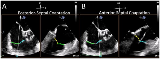
Biplane imaging from the TV commissural view. The mid-oesophageal right ventricular inflow-outflow view (at ∼50–80°) is considered the TV ‘commissural’ view with the anterior (blue line) and posterior (green line) leaflets imaged and the septal leaflet (yellow line) behind the imaging plane. Moving the orthogonal biplane cursor towards the posterior wall (A) images the posterior and septal leaflets. Moving the orthogonal biplane cursor towards the aorta (B) images the anterior leaflet near the aorta and the septal leaflet. TV, tricuspid valve.
The TG level of imaging is essential for TV interventions. Right flexion with ante-flexion creates the TG RV inflow–outflow view and simultaneous biplane imaging at the TV leaflet tips results in a short-axis view of the TV. A single plane short-axis view can be obtained by using only anteflexion, at a mechanical rotation of between 25° and 60°.15 From the short-axis view, the coaptation gaps at the tips of the three leaflets, as well as the exact origin of the TR jet can be assessed. This view may be particularly useful for aligning the clasp arms, particularly when 3D imaging is limited. Further insertion of the probe towards the apex of the heart results in the DT views which aligns the Doppler insonation angle for more accurate measurement of transvalvular flow velocities (Figure 2).
Assessment of valve morphology and function
Precise identification of atrioventricular valve morphology and function is required for pre-procedural planning in order to confirm: (i) severity of regurgitation, (ii) number and location of regurgitant jets, and (iii) suitability of anatomy for the PASCAL repair system. Although suitability for TEER has been delineated,17 defining morphologic suitability for the PASCAL repair system remains speculative at this time although investigators have shown that poor TEER patients may be candidates for this device.5
Mitral valve
Mitral valve morphology: both degenerative and functional MR may be appropriate targets for the PASCAL therapy with anatomic differences previously reviewed.17,18 MV anatomy which may preclude leaflet coaptation device implant or sufficient reduction in MR are shown in Table 1. Specific patient characteristics should always be considered when determining anatomic eligibility. For instance, a patient with a body surface area of 1.5 m2 could have significant reduction in MR without an increase in MV gradient with a baseline MV area of <4.0 cm2.
Anatomic considerations for the PASCAL Repair System
| Inclusion | Suggested anatomic exclusions | |
|---|---|---|
| Mitral regurgitation |
| Mitral valve anatomy precludes proper device deployment and function, including:
|
| Tricuspid regurgitation |
| Tricuspid valve anatomy precludes proper device deployment and function, including:
|
| Inclusion | Suggested anatomic exclusions | |
|---|---|---|
| Mitral regurgitation |
| Mitral valve anatomy precludes proper device deployment and function, including:
|
| Tricuspid regurgitation |
| Tricuspid valve anatomy precludes proper device deployment and function, including:
|
MR, mitral regurgitation; TŖ tricuspid regurgitation.
Mitral valve function: a comprehensive assessment of MV function both at baseline and following device placement includes:
Assessment of MV orifice area and diastolic transmitral gradient: peak and mean transmitral gradients should be recorded along with heart rate.19 In the PASCAL compassionate use report, a single device resulted in a mean MV area reduction of ∼47% and mean gradient = 3.0±1.0 mmHg.5 Because gradients are dependent on loading conditions and chamber compliance, planimetry of the MV orifice at baseline and post-device, should also be performed using 3D volumes (Figure 7). Two devices resulted in a mean MV area reduction of ∼59% and mean gradient = 4.0±1.0 mmHg.
Location and Severity MR: using the ME commissural view, simultaneous biplane imaging with a ‘sweep’ of the MV coaptation zone (Figures 2 and 4) allows the imager to identify the location and approximate size of the regurgitant jet(s). Standard measures of MR severity should be performed as per society guidelines.20,21 However intra-procedurally, the most efficient method for assessing MR severity both at baseline and following device placement is planimetry of the 3D VCA (Figure 3D).22 Finally, following transcatheter leaflet repair, 3D VCA has been shown to accurately assess MR severity23 and predict outcomes.24
Pulmonary venous inflow: systolic reversal of pulmonary vein inflow is a specific sign for severe MR.20 Following leaflet repair, improvement of forward systolic flow in the pulmonary veins has become an important measure of device efficacy, and a predictor of improved outcomes.25,26
Other parameters: following device placement, recent American Society of Echocardiography guidelines suggest other indicators of improvement in MR severity including: appearance of spontaneous contrast in the left atrium, an increase in forward stroke volume and a reduction in ejection fraction.27

Post-device orifice area. Three-dimensional imaging is used to directly planimeter the MV orifice areas separately since the medial and lateral orifices are not typically in the same horizontal plane. Aligning the short-axis plane at the tips of leaflet in diastole (blue lines) allows the lateral orifice area (A) to be planimetered from the short-axis view (blue box). Realigning the short-axis plane for the medial orifice is shown in (B). MV, mitral valve.
Tricuspid valve
Tricuspid valve morphology: similar to MV morphology, TR can be divided in primary and secondary disease. Primary TR is relatively rare with one study showing cardiac implantable devices the most frequent cause.28 Secondary TR is far more common and can be morphologically characterized as atrial functional and ventricular functional TR.29
Tricuspid valve function: a comprehensive assessment of TV function both at baseline and following device placement includes:
Assessment of TV orifice area and diastolic transtricuspid gradient: planimetry of the TV orifice should be performed using 3D multi-planar reconstruction and peak and mean transtricuspid gradients should be recorded along with heart rate.
Location and severity of TR: using the 2D ME RV inflow-outflow view and 3D biplane sweep of the TV coaptation zone, location and approximate size of the regurgitant jet(s) can be determined. Standard measures of of TR severity should be performed as per society guidelines.20,21 However new methods of assessing severity of TR16 as well as an extended severity grading scheme30 is currently being used in early feasibility and pivotal trials of transcatheter TV devices. Recent studies have correlated the extended grading scheme with outcomes.31,32
Hepatic venous inflow: systolic reversal of hepatic vein inflow is thought to be a specific sign for severe TR.20 Following the leaflet repair, improvement of forward systolic flow has been seen.27
Intra-procedural guidance
Intra-procedural guidance of leaflet coaptation devices rely heavily on maximizing the strengths of both 2D and 3D imaging.33 Because of these unique structural and mechanistic features of the PASCAL and ACE devices, imaging can differ from the TEER device. General procedural considerations include: imaging the number and location of chordae which may determine whether to use the PASCAL or the ACE device, and the frequent use of multiple imaging planes to circumvent the acoustic shadowing created by the spacer.
Differences between the imaging steps for the TEER and PASCAL system include the safe introduction of the elongated device followed by implant closure and shortening prior to redirecting to the atrioventricular annular plane. Manoeuvring the shortened device reduces the risk of injury (i.e. the lateral left atrial wall for the mitral and interatrial septum for the tricuspid device). In order to utilize independent leaflet grasping, the individual clasps must be identified. Finally, repositioning by retraction of the elongated device infrequently causes injury to the subvalvular or valvular structures, but nonetheless must be carefully monitored during repositioning of the device.
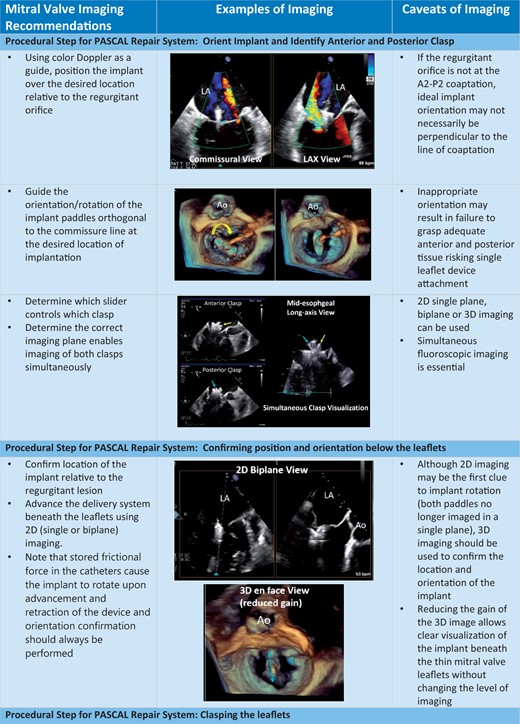
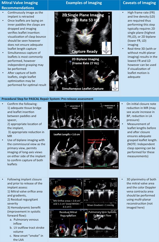
The procedural steps outlined in Table 2, are shown with the essential TEE imaging views for the mitral device (Figure 8A–C) and tricuspid device (Figure 9A–C).

Procedural steps for PASCAL mitral device implantation. (A) The imaging requires for transseptal puncture, advancing the delivery system (2D and 3D guidance) and implant orientation. (B) The next procedural steps of positioning and orientating the device below the leaflets, clasping the leaflets and pre-delivery assessment. (C) The imaging necessary for post-implant assessment of mitral valve function as well as haemodynamic benefit, and safe removal of the delivery catheter.
Continued.
Continued.

Continued.
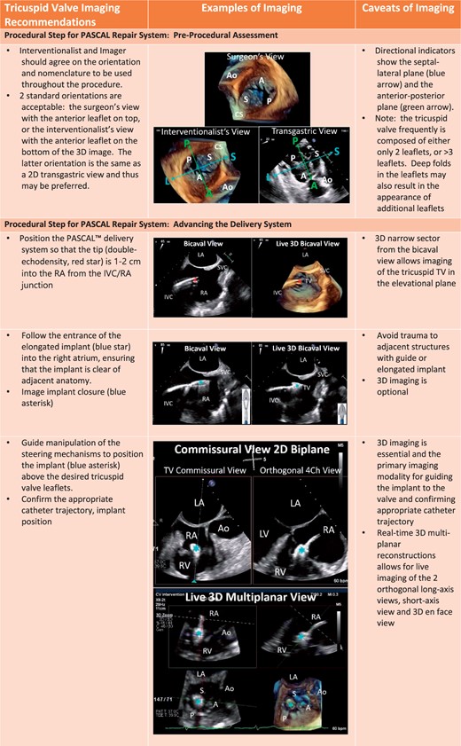
Procedural steps for PASCAL tricuspid device implantation. (A) The imaging requires for pre-device assessment, advancing the delivery system (2D and 3D guidance) and positioning and orientating the device below the leaflets. (B) The next steps of clasping the leaflets and pre-delivery assessment. (C) The imaging necessary for post-implant assessment of tricuspid valve function as well as haemodynamic benefit.
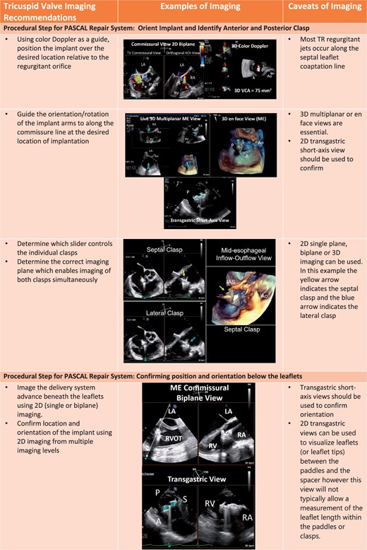
Continued.

Continued.
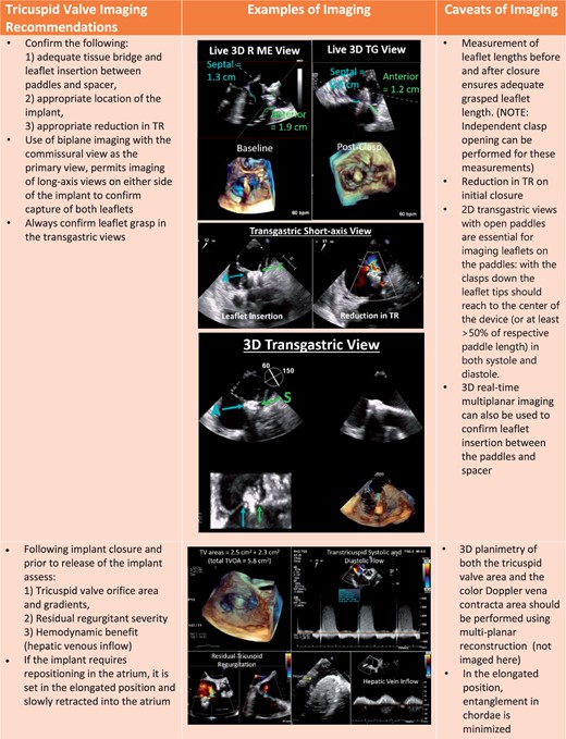
Continued.
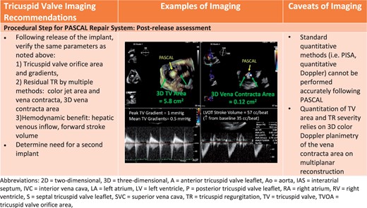
Continued.
Procedural steps for implantation of the PASCAL Repair System
| Procedural steps |
|---|
I. Mitral valve implantation of the PASCAL Repair System
|
II. Tricuspid valve implantation of the PASCAL Repair System
|
| Procedural steps |
|---|
I. Mitral valve implantation of the PASCAL Repair System
|
II. Tricuspid valve implantation of the PASCAL Repair System
|
MR, mitral regurgitation; TŖ tricuspid regurgitation.
Discussion
The PASCAL repair system to treat MR and TR is currently in pivotal trials with pre-procedural TEE required for inclusion, and intra-procedural imaging essential for technical success. The inherent advantages of 2D (greater resolution) and 3D (improved anatomic visualization) should always be considered during each procedural step. The imaging levels and views for the MV have been standardized for commercially available TEER however imaging of the TV remains a challenge given the relationship between the TV and oesophagus previously discussed. Implantation of the TV device typically requires greater probe manipulations and use of multiple imaging planes (ME, DE, TG, and DT) as well as multiple imaging modalities (2D and 3D) to optimize visualization of leaflets within the clasps and confirm adequate leaflet grasp. Extensive probe manipulation as well as longer procedures, increase the risk of complications from TEE imaging.34 Additional imaging modalities such as transthoracic and intracardiac echocardiography (2D and 3D) have been successfully used during these procedures when TEE imaging is limited.9,35 As 3D intracardiac phased array probes become commercially available this imaging modality has the potential to supercede TEE imaging for the TV.
Conclusions
The novel PASCAL transcatheter valve repair system (Edwards Lifesciences, Irvine, CA, USA), has received CE mark for treatment of both MR and TR of either primary or secondary aetiology. Both devices are currently in pivotal trials. Because this device relies heavily on TEE imaging the current imaging review may be useful in patient selection and technical success of the procedure.
Conflict of interest: R.T.H. is a speaker and consultant for Edwards Lifesciences and is the Chief Scientific Officer for the Echocardiography Core Laboratory at the Cardiovascular Research Foundation for multiple industry-sponsored trials, for which she receives no direct industry compensation. S.K.K. reports no relationships relevant to the contents of this article to disclose.
